Abstract
Nowadays, the design trajectories of the executive elements CNC-machines are successfully controlled by computer simulation. But the quality and efficiency of the cutting process cannot be achieved by ensuring the accuracy of movement trajectories of the executive elements. Experimental experience of the rational process modes, tools, cooling and lubricating liquids and etc. was laid in the basis for designing the CNC-program to ensure the equivalent quality of processing. This experience reflects some averaging over a variety of machines, tools and processing conditions. In this case, the changes in the cutting system properties along the motion paths are not taken into account. These changes can be set a priori as changes occurred as a result of the energy released in the cutting zone and then supplied to the machine systems. The article deals with the synergetic alignment of the external (CNC-program) and internal control (dynamic of the cutting process). This paper presents a new approach to the mathematical simulation of a controlled dynamic cutting system, which properties change due to the a priori established laws of parameter changes of interacting subsystems, as well as due to the result of cutting forces acting in the interface of the tool and machining zone. It is revealed that the CNC program with the changing process properties matches regularly that makes it possible to increase the economic efficiency of processing while ensuring the required quality of the batch production of parts.
1. Introduction
Recently, a system-synergetic paradigm of analysis and synthesis has been formed [1], [2]. The synergetic approach is used in the management of complex nonlinear interconnected technical systems [3]-[5], including machining processes for metal-cutting machines [6]-[9], as well as in the study of the dynamics of systems interacting with different environments [10]. The knowledge based on various ideas concerning the influence of process parameters on the machining process [11]-[14] are used for determining the CNC-programs and for setting the trajectories of the executive elements (TEE). It is shown that power released in the cutting zone influences the tool wear. It is estimated, as a rule, by its temperature [12], [14]. Various techniques have been developed for correcting control programs that depend on information exchanges in machine subsystems [15]-[20]. It is shown that the control of elastic deformations of the tool and the workpiece is one of the effective quality control methods for parts manufacturing [18]. This method was recognized in cases that the rigidity of the processed part changes along with the TEE of the machine [19]-[21]. The authors propose to use local systems for automatic control of cutting forces for processing this class of parts. It is also shown that the output processing characteristics depend on the state of the dynamic system (DS) [22]-[28]. It is noted that the cutting DS has the property of evolutionary changes that depend on the power trajectory of irreversible energy transformations in perfect operation [28]-[36]. The next step aimed at improving the processing efficiency is the synergistic alignment of the CNC-program with the cutting dynamic system. First, it is necessary to align the process modes and the corresponding CNC-programs with the cutting DS. Secondly, this alignment ensures the adequacy of system changing properties.
Consequently, the algorithm of alignment control included the determination of the evolutionary trajectory of the system properties and provision of its asymptotic stability while minimizing the intensity of tool wear is proposed based on the study of the influence of the cutting system parameters on the output characteristics of the cutting process. The conditions of control feasibility disclosed in the article that depend on the features of the dynamic cutting system, its state, values of parameters of the tool and workpiece subsystem, namely stiffness, dissipation and inertia matrices, as well as on the technological regimes of cutting: speed and depth of cutting and feed, is taken into account. The materials given in the article are devoted to the alignment of the CNC-program with the properties of the cutting DS that change along the tool path.
2. Mathematical modeling
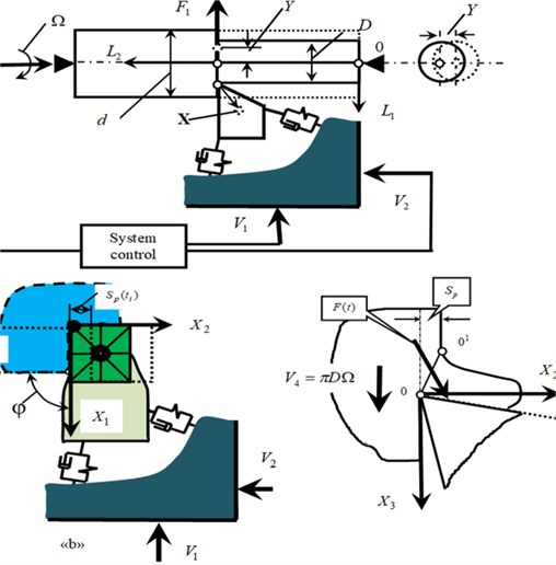
The geometric space tied in the machine’s load-bearing system is considered with established axes in the right center of rotation of the workpiece (Fig. 1). All symbols used in the article are represented in Nomenclature. Additionally, the rotation path of the workpiece () is set. The vectors that characterize the state for the cutting system are introduced for consideration. These vectors are as follows:
The TEE vector for the machines . It indicates at a spatial movement of a caliper and the rotation of a spindle. In the traditional layout . This vector corresponds to the velocity , and phase trajectories . Actually. Combination of and is determined in the CNC-program.
Deformation trajectories and their velocities . It is convenient to consider the deformations in the directions opposite to and .
Trajectories of the shape-generating movements are formed by the rule:
and their speeds , because . If is set, then the main geometry topology of the workpiece surface is determined [7]-[9]. It characterizes the net of tool trace on the part and represents it’s geometric deviation from the ideal position with . The control purpose is determined as:
where is the set of trajectories , which provide the required geometric topology of the surfaces formed by cutting.
When the tool intersects the workpiece, complex physical interactions are formed in the cutting zone, represented in the form of a dynamic relationship formed by cutting. This connection combines the physical subsystems into a single cutting system. In this study, only mechanical subsystems are considered. Then the interaction is characterized by forces , that cause elastic deformations . Parameters that characterize the intersection of the tool and the workpiece, are included in the process mode (feed, depth and cutting speed): . They are related to trajectories and by the ratio:
where is the turnaround time .
Fig. 1Scheme of interaction of spindle rotation drives and caliper feed, and formation of dynamic link of cutting process
It is assumed that there are no torsional deformations of the workpiece, and the workpiece has a constant diameter, and the system is considered unperturbed. Consequently, feed is defined by the integration operator of the total speed in the time window determined by the rotation frequency of the workpiece. If in Eqs. (3-5) there are no deformations, and all velocities are constant, then . This paper uses studies [32] to determine the deformations in Eq. (3-5):
where , , at , , at , , , , in kgs2/mm, in kgs/mm, , , , , , in kg/mm – symmetric, positive-definite matrices of inertial, speed, and elastic coefficients; stiffness of workpiece . Projections in a space are determined by coefficients , 1, 2, 3 that meet the following conditions . The is taken into account. Coefficients depend on the geometry of the tool and are unchanged, if wear is not taken into account. The coefficients and matrices change depending on the trajectory when processing a part with a complex geometry. The possibility to consider workpiece deformations in a scalar form is explained by the round section of the workpiece. Then any orthogonal coordinate system normal to the axis of rotation is the principal one.
One of the provisions of synergetic analysis and synthesis uses the principle of expansion-contraction of the dimensionality of the state space [3]-[5]. In this case, the introduced system of equations reveals the link of the forces with deformation displacements Eq. (4), in which it is necessary to express the forces through coordinates of the state and TEE are related to the process modes. The following properties of the force generation are taken into account when the longitudinal rotation takes place. The force modulus is proportional to the shear area () (Fig. 1), and its changes delay in relation to its variations [22]-[24]. As the cutting speed increases in the speed range (0.5-3.0) m/s, its increase causes an exponential decrease in forces [32]. The feed rate is the path taken by the tool tip in the longitudinal direction during the workpiece rotation.
The force model is considered. The dependence on the area of the cut layer , the cutting speed and delayed impact of all forces acting in this model is taken into account. Then:
where:
where is the chip pressure[kg/mm2]; is the force steepness parameters [s/mm]; is the dimensionless coefficient; is the parameter that determines the delay of forces. Systems Eq. (1-5) allow finding out the relationship of the machine TEE with , and, consequently, determining and providing Eq. (2).
3. Desired attractor construction
As noted, the control purpose consists in selecting the optimal TEE and to minimize the cost of a batch production, taking into account the condition of Eq. (2). It is necessary to choose and satisfying the condition of Eq. (2) to solve this task, first of all. A set of TEE is used to form the following equation:
where is a set of asymptotically stable trajectories. Then it is necessary to define , trajectories and from that provide the possibility to reduce the cost of a batch production to a minimum. The sequence of solutions to the problem of asymptotical stability is considered.
In the first step, the trajectories and providing the deviation of the diameter are determined, and the asymptotically stable trajectories are chosen from among them. The most rational condition is used to estimate the feed rate . First, the trajectories of the set are determined. The task of determining is set when the diameter deviation . The function is considered constant within the impulse response of the system. Then this system can be used to determine the connection between and :
where:
In Eq. (10), all parameters are set, including , and the law of is determined, which is the phase trajectory of the longitudinal movement of the caliper. Defined machine system TEEs are hidden in Eq. (10) in the parameters , . Their set determines the set of trajectories . From this set, it is necessary to select trajectories that satisfy TEE stability. Then is an attractor, which is the basis of the synergetic control theory [3]. It is necessary to obtain a linearized equation in variations and investigate it by known techniques to analyze the stability [33]. Without dwelling on details, please see a linearized equation in the vicinity of equilibrium in variations corresponding to Eq. (6) and Eq. (7):
where:
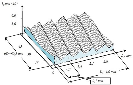
The synthesis of control is illustrated by turning the of the fuel system fitting made of steel grade C45. Length 120 mm, 20 mm, technological modes: 2,0 mm, 2,0 m/s. The parameters are given in Table 1 and Table 2. The generalized masses: 0,5⋅10-3 kg⋅s2/mm, , and depend on the movement (Fig. 1).
In this example, the trajectories of stiffness , deformation displacements and velocity providing are given (Fig. 2).
Table 1Matrices of velocity coefficients
0.25 | 0.15 | 0.15 | 0.1 | 0.08 | 0.08 | 0.18 |
Table 2Matrices of elasticity coefficients
1000 | 800 | 800 | 200 | 100 | 100 | 200-300 |
Table 3Parameters of dynamic link
, [kg/mm2] | , m/s | , | |
500 | 0.1 | 0.001-0.005 | 0.5 |
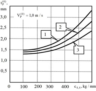
Fig. 2Change of system properties along the axis L2: a) trajectory of radial stiffness change c4,4 (1) and rational feed rate trajectory V2 (2); b) error caused by elastic deformations ΔΣ at constant feed (1), at constant force (2), at feed rate control (3)
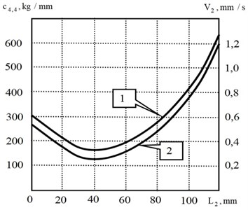
a)
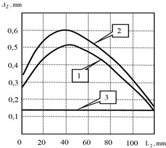
b)
Depending on the parameters (Fig. 3), the trajectory may become unstable. To provide , it is necessary to change the parameters of the subsystems by constructive methods or to adjust the cutting speed and the corresponding feed rate . Fig. 3 shows that the stability region always expands as the velocity increases. Earlier it was shown that as the velocity in the system increases, parametric self-excitation is observed [8]. Therefore, there is a range in which the stability margin is maximal. It also characterizes the range of variations in which the system always suppresses perturbations [34]. Here is a mutual influence of different physical processes that cause minimization of tool wear intensity.
At the second stage, trajectories are selected from the set , which provide a minimum of the reduced cost of a batch production [35]. The relationship between the intensity and rate of tool wear and the power of irreversible transformations of the energy input to the cutting zone is taken into account [29], [30]. From the dependence of the dynamic coupling parameters on wear, an evolutionary restructuring of the properties is observed. This is a slow process that requires trajectory correction. The wear rate can be represented by the integral equation [29], [30]:
where , are coefficients in [s-1] and [kg-1]; , are constants in [s]; is the kernel of the integral operator ; is power of irreversible transformations in [kg⋅m/s]. The kernel includes the process of adaptation (the first term) and degradation (the second term). Then:
The power from Eq. (7) is determined by:
Systems of Eq. (6), Eq. (7), and Eq. (11) represent functionally coupled integro-differential equations which methods of analysis are described in [29], [30]. Here, the power released in the cutting zone is actually a generator for the development of wear, changes in the parameters of the dynamic coupling and evolutionary restructuring of the system properties. Moreover, each evolutionary diagram, including the diagram of forces, deformation displacements and power of irreversible energy transformations is unique. They correspond to skeleton geometric topology diagrams, from which one can determine the accepted in engineering practice assessments of a quality of the surface being formed. It depends on the initial parameters, modes and perturbations. Therefore, even their small variations can correspond to different diagrams of wear and changes in the geometric characteristics of the surface formed by cutting. As our studies show, all evolutionary diagrams are characterized by the development of chaotic dynamics, so there is a limit cutting path after which machining is impossible [35], [36]. Consequently, all the output characteristics of the process, including the geometric topology and wear, evolve to their terminal state due to the energy of irreversible transformations.
Therefore, trajectory determination is associated with step-by-step correction of the TEE (CNC program) of the machine tool during the evolution of the cutting system, so as to provide the maximum path to reach the terminal state.
Fig. 3Stability areas of “frozen” system at different values of wear w0: 1 – w0= 0.05; 2 – w0= 0.1; 3 – w0= 0.15
a)
b)
4. Dynamic peculiarities and control and dynamics coordination
Some examples of evolutionary diagrams (Fig. 4) are given, and the identified features of evolutionary trajectories are considered. These examples are as follows:
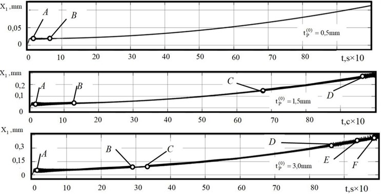
1) Unchanged machining modes and conditions demonstrate evolutionary changes in the properties of deformations, forces and power of irreversible energy transformations, hence tool wearability. Each evolutionary trajectory depends on a variety of initial parameters and modes. In the trajectories (Fig. 4), there are noticeable differences, at least in the location of the bifurcation points (marked "A", "B", ..., "F"). These diagrams have significantly different trajectories of power and work of irreversible transformations reduced to the cutting blade length.
Fig. 4Example of evolution diagrams of tool strain displacements in direction X1 at different depths of cutting
2) In the course of evolution, bifurcations of the attracting sets of strains and a monotonic shift of their constant component are observed. Therefore, the diameter deviation is determined, first, by an a priori set law , and, second, by an evolutionary change in the parameters, first of all, by . The location of bifurcation points and their type depend on the system parameters, first of all, on the excitation coefficient determined by and . Here, the variety of phase-space topologies increases together with the increase of . The cutting system itself, in which the forces are represented in the state coordinates and modes, can be interpreted as a dynamic system with feedback. Therefore, the first problem of matching the machine tool TEE includes the choice of such their trajectories, at which the condition of Eq. (2) is accomplished. This is a synergistic paradigm of matching the external (from the CNC system) and internal (from the forces represented in the state coordinates) control [3].
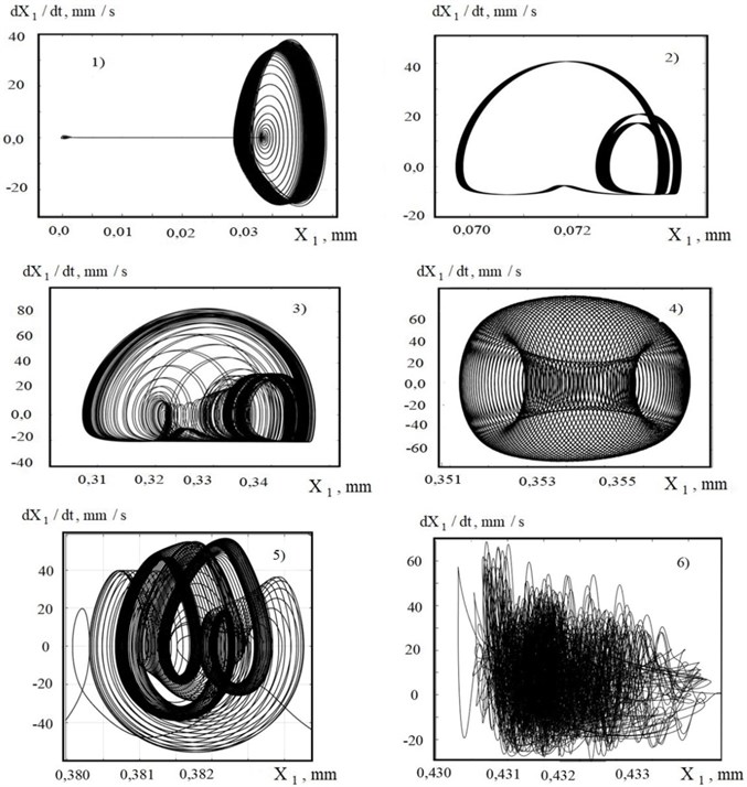
3) The bifurcations for 3,0 mm are analyzed. At all of them , the loss of stability and the formation of self-oscillations are observed along the cutoff (Fig. 5, curve 1). This is due to the change in the parameter , which depends on the thickness of the cut layer, when plunging, and its influence on the stability. The stable section corresponds to the part of the tool wear curve, on which the wear intensity is minimal. Bifurcations become more frequent, when wear approaches the values of (0.8-0.9) mm, corresponding to the beginning of catastrophic wear. Depending on the parameters, the bifurcation points shift. Transformation of one limit cycle into another (curve 2 in Fig. 5) is observed, which is further transformed into a torus (curve 4), and then chaotic dynamics is formed in the system (curve 6). The transition from a limit cycle to a torus is shown by trajectory 3, and from a torus to a chaotic attractor by trajectory 5. This is accompanied by a cascade of period-doubling bifurcations. The bifurcation diagrams for varying the cutting speed are also analyzed, and it is shown that the value of cutting speed, at which the intensity of wear is minimal, changes in the course of evolution. In contrast to existing ideas about the existence of an optimal cutting speed, but unchanged along the trajectory, the performed research shows that it is necessary to consider the optimal trajectory along the work done by cutting, that is, along the displacement. In addition, tool wear depends on the parameters of the dynamic system and, first of all, uncontrolled vibration disturbances [36], [37].
4) Each type of phase space topology corresponds to its own skeleton geometric surface topology (Fig. 6). Studies have shown that when analyzing the representation of vibration processes in the geometrical topology, it is necessary to take into account the following features: vibrations cause a dynamic shift of the balance point, changing the current diameter value; an increase in the intensity of vibrations in the high frequency region causes vibration linearization of the dynamic relationship formed by cutting, and in most cases the vibration suppression in the low frequency region; the geometrical topology is affected not only by the orientation of vibrations in space, but also by the ratio of frequency; there are directions in which vibrations, changing the overall dynamics, do not affect the geometric topology formed by cutting.
Fig. 5Examples of fragments of projections of phase trajectories on plane X1-dX1/dt in course of evolutionary restructuring
The efficiency of matching the machine TEE and changing cutting dynamics has been tested in a factory when machining parts which stiffness changes along the tool travel. Reference points were selected on the workpiece, between which a linear interpolation of the feed rate and its corresponding sets of speeds and .
The set is divided into three groups according to the values of optimum cutting speed on the sections. Experimentally it is possible to reduce machine time by almost 2.5 times due to reducing the number of passes and increasing the integral value of tool wear resistance. Performed digital experiments showed that with continuous alignment of speeds and and with evolution of the system the machine time for part machining is reduced up to three times due to the selection of the optimal cutting speed along the trajectory. It is important to emphasize that the increase in process efficiency is achieved solely by software methods.
Fig. 6Example of skeleton geometrical topology when machining a shaft with diameter D= 20.0 mm: a) path of deformation displacements X1; b) net of geometrical topology
a)
b)
5. Result analysis
The results obtained in the framework of the study showed that the cutting system as a control object is a complex interrelated nonlinear system, which is represented as cutting forces in the state coordinates but these forces actually include the forces as an internal regulator of the trajectories of shape-forming movements and machining properties. The results of the study allowed us to formulate some significant principles of control alignment.
Firstly, since the evolutionary properties of the system depend on the parameters of the dynamic system and disturbances, the matching process is performed for a specific machine and process. Rational directions for matching the machine tool TEE with the evolutionary properties of the cutting process depend on the features of the workpiece and the terminal target. To ensure the constancy of the diameter of the workpiece, which stiffness parameters along its axis are set a priori, it is also reasonable to ensure the constancy of the elastic deformation displacements of the tool relative to the workpiece on the basis of variations in the feed rate and the corresponding cutting speeds and feed rates.
Thirdly, in its turn, the cutting speed is selected from the conditions of tool wear intensity minimization that correspond to the trajectories with the largest stability margin of the system. As evolutionary change of parameters is observed due to the energy release in the cutting zone, each stage of evolution determined by the produced force work corresponds to its optimal cutting speed value, and these properties can be transferred to other equipment with great caution.
Finally, cutting forces which disclose the dependence between elastic deformations and process modes extremely affect the deformation process. In this case, the stabilization of cutting forces leads to even greater diameter error than machining without control at constant modes (Fig. 3). This is due to the properties of self-regulation of the cutting process. If, on the other hand, the allowance variation is the main variable parameter, then forces stabilization through feed variation can fully compensate for the effect of allowance variation on the diameter accuracy. In all cases, it is necessary not to stabilize the cutting forces, but to ensure the constancy of the elastic deformations on the basis of their coordination with the law of change in the cutting properties and a priori specified disturbance.
6. Conclusion
The cutting process that takes place on metal-cutting machines is a complex nonlinear hierarchically interconnected system in which the properties of machining and its output characteristics change in the course of machining, firstly, as a result of a priori set laws of change in the interacting subsystems along the cutting path. Secondly, the system parameters depend on the energy released in the cutting zone and, as a consequence, these system properties are evolutionarily restructured. The above example of such alignment for machining parts which stiffness varies along the tool path can be extended to other cases and motion control processes of mechanical systems interacting with different environments.
References
-
H. Haken and A. M. Fraser, “Information and self‐organization: a macroscopic approach to complex systems,” American Journal of Physics, Vol. 57, No. 10, pp. 958–959, Oct. 1989, https://doi.org/10.1119/1.15809
-
I. Prigogine and C. George, “The second law as a selection principle: The microscopic theory of dissipative processes in quantum systems,” Proceedings of the National Academy of Sciences, Vol. 8, pp. 4590–4594, 1983.
-
A. A. Kolesnikov, Synergetic Theory of Control. Moscow: Energoatomizdat, 1994.
-
A. A. Kolesnikov, A. A. Kolesnikov, and A. A. Kuzmenko, “ADAR method and theory of adaptive control in the tasks of synthesis of the nonlinear control systems,” (in Russian), Mechatronics, Automation, Control, Vol. 18, No. 9, pp. 579–589, Sep. 2017, https://doi.org/10.17587/mau.18.579-589
-
A. A. Kolesnikov, A. A. Kolesnikov, and A. A. Kuz’Menko, “Methods of ACAR and ACOR in the problems of synthesis of nonlinear control systems,” (in Russian), Mechatronics, Automation, Control, Vol. 17, No. 10, pp. 657–669, Oct. 2016, https://doi.org/10.17587/mau.17.657-669
-
V. L. Zakovorotny, M. B. Fleck, and D. T. Pham, “Synergetic concept in the construction of precision control systems for manufacturing parts of complex geometric shapes,” (in Russian), Bulletin of the Don State Technical University, Vol. 11, No. 10(61), pp. 1785–1797, 2011.
-
V. L. Zakovorotny, A. A. Gubanova, and A. D. Lukyanov, “Stability of shaping trajectories in milling: Synergetic concepts,” Russian Engineering Research, Vol. 36, No. 11, pp. 956–964, Nov. 2016, https://doi.org/10.3103/s1068798x16110216
-
V. L. Zakovorotnyi, A. A. Gubanova, and A. D. Luk’Yanov, “Parametric self-excitation of a dynamic end-milling machine,” Russian Engineering Research, Vol. 36, No. 12, pp. 1033–1039, Dec. 2016, https://doi.org/10.3103/s1068798x16120194
-
V. L. Zakovorotny and V. E. Gvindzhiliya, “Influence of spindle wobble in a lathe on the tool’s deformational-displacement trajectory,” Russian Engineering Research, Vol. 38, No. 8, pp. 623–631, Aug. 2018, https://doi.org/10.3103/s1068798x1808018x
-
V. L. Zakovorotny, M. B. Flek, and E. A. Ugnich, “Synergetic approach to the modeling of industrial enterprise’s economic activity,” International Journal of Economic Perspectives, Vol. 10, No. 4, pp. 371–375, Jan. 2016.
-
V. K. Starkov, Physics and Optimization of Cutting Materials. Moscow: Mashinostroenie, 2009.
-
V. Lapshin, V. Khristoforova, and S. Nosachev, “Relationship of temperature and cutting force with tool wear and vibration in metal turning,” (in Russian), Metal Working and Material Science, Vol. 22, No. 3, pp. 44–58, Sep. 2020, https://doi.org/10.17212/1994-6309-2020-22.3-44-58
-
P. Blau, K. Busch, M. Dix, C. Hochmuth, A. Stoll, and R. Wertheim, “Flushing strategies for high performance, efficient and environmentally friendly cutting,” Procedia CIRP, Vol. 26, pp. 361–366, 2015, https://doi.org/10.1016/j.procir.2014.07.058
-
G. Kant and K. S. Sangwan, “Prediction and optimization of machining parameters for minimizing power consumption and surface roughness in machining,” Journal of Cleaner Production, Vol. 83, No. 83, pp. 151–164, Nov. 2014, https://doi.org/10.1016/j.jclepro.2014.07.073
-
G. M. Martinov, A. B. Ljubimov, and L. I. Martinova, “From classic CNC systems to cloud-based technology and back,” Robotics and Computer-Integrated Manufacturing, Vol. 63, p. 101927, Jun. 2020, https://doi.org/10.1016/j.rcim.2019.101927
-
G. M. Martinov, S. V. Sokolov, L. I. Martinova, A. S. Grigoryev, and P. A. Nikishechkin, “Approach to the diagnosis and configuration of servo drives in heterogeneous machine control systems,” Lecture Notes in Computer Science, Vol. 10386, pp. 586–594, 2017, https://doi.org/10.1007/978-3-319-61833-3_62
-
Z. Sang and X. Xu, “The framework of a cloud-based CNC system,” Procedia CIRP, Vol. 63, pp. 82–88, 2017, https://doi.org/10.1016/j.procir.2017.03.152
-
B. M. Bazrov, Adaptive Control of Machine Tools. Moscow: Mashinostroenie, 1973.
-
A. A. Zhdanov, A. L. Plotnikov, Yu. L. Chigirinsky, and I. V. Firsov, “Mathematical model for refining cutting modes for ensuring the accuracy of non-rigid shaft turning on CNC machines,” (in Russian), Scientific Works of World, Vol. 4, No. 41, pp. 41–47, 2015.
-
A. V. Bobrovsky and O. I. Drachev, “Technology of mechanical processing of low-rigid axisymmetric parts,” (in Russian), Proceedings of the Volgograd State Technical University, Vol. 232, No. 9, pp. 15–17, 2019.
-
O. I. Drachev, “System of automatic control of operational accuracy of long-length shafts,” (in Russian), Proceedings of the Volgograd State Technical University, Vol. 200, No. 5, pp. 18–20, 2017.
-
V. A. Kudinov, Dynamics of machine tools. Moscow: Mashinostroenie, 1967.
-
S. A. Voronov and I. A. Kiselev, “Nonlinear problems of the dynamics of cutting processes,” (in Russian), Mechanical Engineering and Engi-neering Education, Vol. 51, No. 2, pp. 9–23, 2017.
-
A. M. Gouskov, S. A. Voronov, H. Paris, and S. A. Batzer, “Nonlinear dynamics of a machining system with two interdependent delays,” Communications in Nonlinear Science and Numerical Simulation, Vol. 7, No. 4, pp. 207–221, Dec. 2002, https://doi.org/10.1016/s1007-5704(02)00014-x
-
G. Stépán, T. Insperger, and R. Szalai, “Delay, parametric excitation, and the nonlinear dynamics of cutting processes,” International Journal of Bifurcation and Chaos, Vol. 15, No. 9, pp. 2783–2798, Sep. 2005, https://doi.org/10.1142/s0218127405013642
-
W. T. Corpus and W. J. Endres, “Added stability lobes in machining processes that exhibit periodic time variation, part 1: an analytical solution,” Journal of Manufacturing Science and Engineering, Vol. 126, No. 3, pp. 467–474, Aug. 2004, https://doi.org/10.1115/1.1765137
-
Hasnul Hadi, Liyana Tajul, Z. A. Zailani, M. F. M. A. Hamzas, and M. S. Hussin, “The parametric effect and optimization on JIS S45C steel turning,” International Journal of Engineering Science and Technology, Vol. 3, No. 5, pp. 479–487, May 2011.
-
R. Rusinek, M. Wiercigroch, and P. Wahi, “Influence of tool flank forces on complex dynamics of cutting process,” International Journal of Bifurcation and Chaos, Vol. 24, No. 9, p. 1450115, Sep. 2014, https://doi.org/10.1142/s0218127414501156
-
V. L. Zakovorotny and V. E. Gvindjiliya, “Link between the self-organization of dynamic cutting system and tool wear,” (in Russian), Applied Problems of Nonlinear Oscillation and Wave Theory, Vol. 28, No. 1, pp. 46–61, Feb. 2020, https://doi.org/10.18500/0869-6632-2020-28-1-46-61
-
V. L. Zakovorotny and V. E. Gvindjiliya, “Bifurcations of attracting sets of cutting tool deformation displacements at the evolution of treatment process properties,” (in Russian), Applied Nonlinear Dynamics, Vol. 26, No. 5, pp. 20–38, 2018, https://doi.org/10.18500/0869-6632-2018-26-5-20-38
-
V. P. Lapshin, I. A. Turkin, and V. V. Khristoforova, “Assessment of metal wear in turning on the basis of components of the cutting force,” Russian Engineering Research, Vol. 40, No. 9, pp. 797–800, Sep. 2020, https://doi.org/10.3103/s1068798x20090099
-
V. L. Zakovorotny, D. T. Pham, and X. T. Nguyen, “Mathematical modeling and parametric identification of dynamic properties of the sub-systems of the cutting tool and workpiece in the turning,” (in Russian), Technical Sciences, Vol. 160, No. 2, pp. 38–46, 2011.
-
A. M. Lyapunov, The General Problem of Motion Stability. Moscow: Gostekhizdat, 1950.
-
V. Zakovorotny, “The influence of fluctuation on the shape-generating trajectories stability with a turning,” University News. North-Caucasian Region. Technical Sciences Series, No. 2, pp. 52–61, Mar. 2017, https://doi.org/10.17213/0321-2653-2017-2-52-61
-
V. Zakovorotny and V. Gvindjiliya, “Determination of optimal coordinates for switching processing cycles on metal-cutting machines,” (in Russian), Metal Working and Material Science, Vol. 23, No. 1, pp. 56–67, Mar. 2021, https://doi.org/10.17212/1994-6309-2021-23.1-56-67
-
V. Zakovorotny and V. Gvindjiliya, “Influence of cutting dynamic on the selection of the technological regimes to ensure minimal wear of cutting tools,” (in Russian), Metal Working and Material Science, Vol. 22, No. 4, pp. 54–70, Dec. 2020, https://doi.org/10.17212/1994-6309-2020-22.4-54-70
-
S. Orhan, A. O. Er, N. Camuşcu, and E. Aslan, “Tool wear evaluation by vibration analysis during end milling of AISI D3 cold work tool steel with 35 HRC hardness,” NDT and E International, Vol. 40, No. 2, pp. 121–126, Mar. 2007, https://doi.org/10.1016/j.ndteint.2006.09.006
About this article

This study was performed with a financial support by RFBR grants: “Development of the Analysis and Synthesis Theory of Controlled Self-Organization in a Dynamic Cutting System during Processing on the Example of Manufacturing Parts on Lathes”, No. 19-08-00022; “Development of Methods for Analysis and Synthesis of a Dynamic Cutting System Based on the Criterion of Minimizing the Reduced Manufacturing Costs”, No. 20-38-90074.
