Abstract
High-temperature gas will cause stress and deformation of the rotor during the operation of the twin-screw compressor, which will affect the structural performance of the screw rotor. Based on the CFD/CSD coupling solution technology, the method of thermal solid numerical analysis is developed. The fluid control equations are time-averaged differential equations, and the turbulence model is a two-equation Realizable - model. The thermal deformation and thermal stress of the rotor are obtained by solving the structural static equilibrium equation. The reliability of the proposed method is verified by solving the thermal deformation of the L-shaped large-diameter buried pipeline. Finally, the thermal deformation and thermal stress of the rotor under different exhaust pressures and different speeds are mainly studied. Through simulation analysis, the variation law of rotor deformation, stress and modal under different temperature fields of the compressor is obtained, which can provide a certain theoretical reference for the compressor structural design and optimization.
Highlights
- The temperature of the compressor screw rotor wall is distributed in a herringbone shape when the compressor is operating stably.
- The temperature at the discharge side of the compressor is the highest, and the temperature at the suction side is lower.
- From the discharge end to the suction end of the compressor, as the axial length of the rotor increases, the deformation of the female-male rotor gradually increases.
1. Introduction
In recent years, with the rapid development of Chinese economy, huge progress has been made in construction, industrial manufacturing, cold chain logistics and other fields. These areas have also driven the rapid development of compressors [1]. As a relatively new type of screw compressor, its working principle realizes the three processes of gas suction-compression-discharge through the meshing of the screw rotor. During the operation of the twin-screw compressor system, the engagement of the screw rotor is prone to generate various physical fields such as heat, sound, and structure field, among which the temperature and structure field have a greater impact on the screw rotor meshing [2]. The meshing of the female and male rotors produces an uneven ambient temperature field, and its heat distribution affects the dynamic performance and compression efficiency of the screw rotor to varying degrees. At the same time, the working process of the twin-screw compressor is periodic, resulting in a more severe coupling of temperature field and structural field [3].
At present, the research of twin screw compressors is mainly focused on the flow field and structure field in the compressor. Foreign scholar John et al. [4] used sliding grid technology to simulate the internal flow field of screw compressors, which solved the difficulty of adapting the block grid for a long time. Stosic et al. [5] uses a micro-injection method to cool the rotor structure of a new type of oil-injected compressor, and uses a computer to simulate the temperature field of the rotor. As a result, it is found that the temperature of the rotor is significantly reduced and the pressure ratio of the compressor is greatly increased. Sauls [6] study for heat transfer and heat exchange of the wall surface of the rotor screw compressor, resulting thermal performance of the compressor cylinder and the rotor at the actual gap. Mustafin et al. [7] designed and proposed a numerical simulation method to calculate the temperature field of the rotor in the working state, and analyzed the influence of the structural parameters and working conditions of the screw compressor on the rotor temperature field. Hsieh et al. [8] proposed a mathematical model and calculation program for screw compressors. The Helmholtz equations were derived by solving the partial differential equation of transient heat conduction without internal heat, and the temperature distribution of the inner and outer rotors of the oil-injected screw compressor was calculated more accurately.
Domestic scholars are studying the flow field in the compressor. Cao et al. [9] have designed a mathematical model that can describe the pressure distribution in the working cavity of the twin screw compressor in detail, and obtained the pressure distribution in the cavity through experiments, which can clearly understand the force situation of the twin screw compressor in the actual working process. Tang et al. [10] simulated the periodically changing internal flow field of the twin screw pump through different instantaneous flow field models, and verified that the steady-state flow field of different instantaneous flow can be used to replace the unsteady flow field of the screw pump. Wu et al. [11] used Fluent software to simulate the internal flow field of the twin screw compressor, and obtained the pressure distribution trend of the flow field in the compressor. Long et al. [12] used STAR-CCM+ software to simulate the internal flow field of the screw compressor, and proved that the pressure value of the flow field in the compressor periodically changed with time. He et al. [13] increased the meshing clearance and tooth clearance of the twin screw compressor rotor to millimeter level through ANSA and Fluent software, which provided a method for accurately analyzing the pressure change of the flow field in the compressor. Feng [14] studied the structural characteristics of the complex surface screw rotor based on the fluid-solid coupling analysis method, and analyzed the influence of the compressor pressure field on the rotor performance. In studying the temperature on the performance of the screw rotor, Zhou et al. [15] conducted a comprehensive analysis of the thermal deformation of the symmetric screw flowmeter rotor based on the finite element theory, and deduced the effect of thermal deformation on the leakage and operation of the screw rotor. Cao et al. [16] based on the theory of elastic mechanics and finite element method, used the first type of thermal boundary conditions to analyze the three-dimensional steady-state temperature field of the rotor, solving the problem that the deformation of the 3D screw rotor can only be simplified to 2D calculation for a long time. Wang et al. [17] used the finite element method to analyze the thermal stress of the screw rotor, and accurately analyzed the true stress, deformation and constrained reaction force of the rotor, which solved the problem that the simplification and accuracy of the screw rotor force deformation is too low for a long time. Chen et al. [18] simulated the temperature field and thermal deformation of the screw vacuum pump rotor, and obtained the distribution of the screw rotor temperature field and the radial deformation of the rotor. Cui et al. [19] used the finite element method to analyze the temperature field of the pump cavity system of the screw vacuum pump and the thermal deformation law of the rotor, and obtained the influence law of the thermal deformation on the gap in the pump cavity. Wei et al. [20] adopted indirect coupling and weak coupling methods to realize the multi-field coupling of temperature field, flow field and stress field for a new twin-screw kneader. It was obtained that the thermal deformation caused by the temperature field is the most important factor affecting the rotor deformation.
The above scholars did not consider the influence of the temperature field generated during the working process of the compressor on the structural performance of the screw rotor in the study of the twin screw compressor. Due to the hermeticity of the compressor, it is difficult to study the heating condition of the rotor tooth surface through the test method. Therefore, the temperature field of the compressor is calculated based on the finite volume method, and the CFD/CSD numerical interpolation technique is used to apply the temperature load as an external load to the rotor tooth surface. Finally, the influence of the compressor temperature field on the rotor structure is studied by solving the rotor structural static balance equation.
2. Calculation method
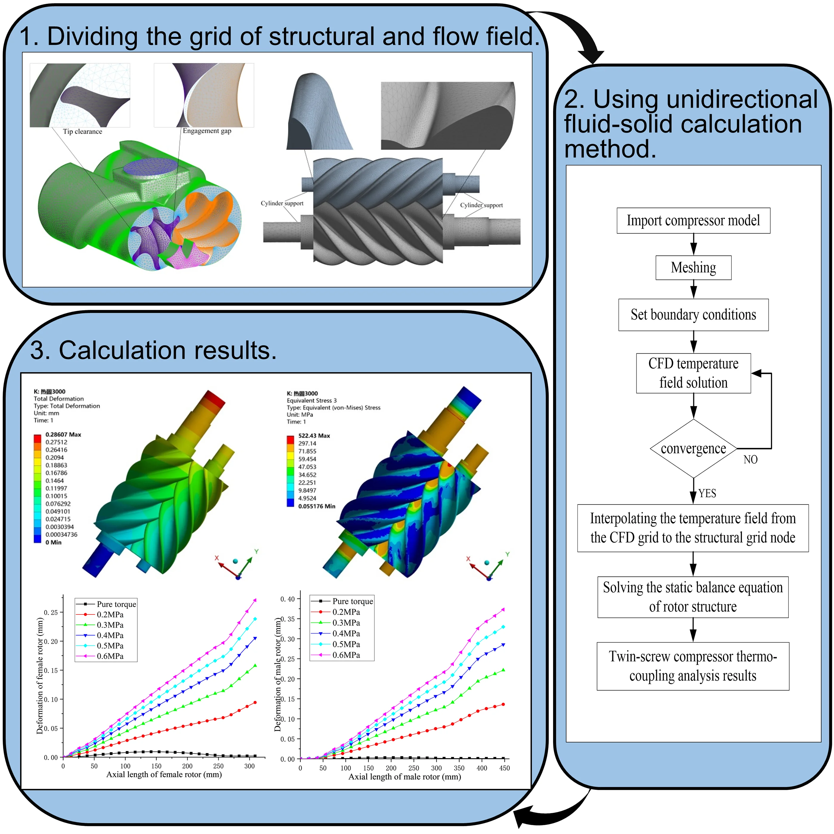
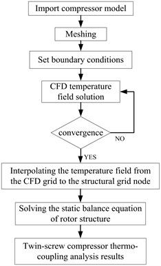
This article uses Fluent and Static Structural modules in the Workbench platform. Based on the loosely coupled one-way thermo-solid coupling calculation method, the internal flow field of the compressor is obtained by solving the N-S control equation, and the temperature field is loaded on the structural grid of the rotor using numerical interpolation technology after the flow field converges. Finally, the displacement and stress fields of the rotor structure are obtained by solving the static balance equation of the rotor structure. The specific process is shown in Fig. 1.
Fig. 1Flow chart of thermal-solid coupling
2.1. Flow field solving technology
Because the compressor is under variable heat load for a long time, the cycle is short, and the thermal field changes little. Therefore, a quasi-transient thermo-solid coupling numerical simulation can be performed on the compressor after the compressor reaches thermal equilibrium [21-23]. The continuity equation, momentum conservation equation and energy conservation equation of the fluid in the compressor flow field are respectively [24]:
where, is the velocity vector; is the fluid pressure. is the dynamic viscosity of the fluid. is the specific heat capacity of the fluid. is the density of the fluid. is the thermal conductivity. is the mass force acting on the fluid. is the heat absorbed by the fluid. is fluid temperature. is energy dissipation function.
2.2. Structural solving technology
When transmitting data at the fluid-solid coupling interface, the displacement, stress, heat flow, temperature and other conservation of fluid and solid should be satisfied:
where, is the fluid domain. is a solid domain.
The temperature field and thermoelastic finite element equations of the thermosetting unidirectional calculation model are [25]:
where, is a heat capacity matrix. is a temperature vector. is time. is a heat conduction matrix. is a heat flow vector. is a stiffness matrix. is a displacement vector. is a thermal stress coefficient matrix. is a mechanical force vector.
In this paper, a steady-state thermal analysis is performed on a twin-screw compressor, which has nothing to do with the time term, so in the Eq. (5) is 0. After the finite element is used for discrete, the element equation of the finite element is obtained, the temperature field at the steady state moment is solved, and the temperature field is brought into the thermoelastic Eq. (6) to obtain the displacement field and stress distribution of the steady state analysis.
3. Validation
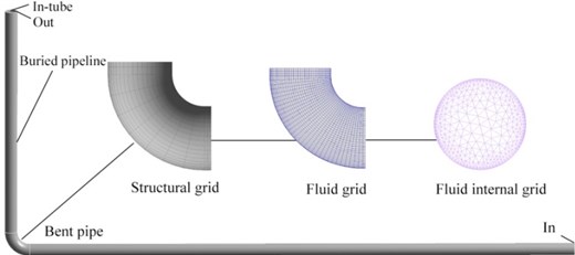
In order to verify the accuracy of the thermal-solid coupling calculation method in this paper, the L-shaped large-diameter buried pipeline is taken as the research object [26]. The thermal-solid coupling calculation method in the paper is used to calculate the thermal deformation under the effect of temperature. The geometric model of the pipeline, the pipeline structure grid and the fluid domain grid are shown in Fig. 2.
Fig. 2Buried pipeline
During the calculation, the turbulence model uses standard - and SIMPLEC solution algorithms. The fluid inlet is set as a pressure inlet, the pressure value is 1.6 MPa, and the inlet temperature is 140 °C. The outlet is set as the mass flow outlet, and the solid wall surface adopts the non-slip boundary condition. The internal working medium of the pipe is water and the pipe material is Q235B. When the thermal coupling is solved, the entrance and exit of the pipe are set to have no displacement constraints. The numerical simulation results and experimental data are compared as shown in Table 1. The results show that the simulation results of the fluid inlet velocity, inlet pressure, inlet temperature, outlet pressure, and outlet temperature of the buried pipeline are within 2 % of the data provided in the experiment. The flow field calculation method in this paper is reliable.
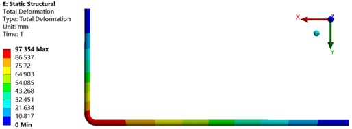
Fig. 3 is a cloud diagram of the pipeline results under the temperature load. The deformation distribution of the pipeline under the temperature load is the same as the deformation trend under the temperature load in the literature. The deformation is 97.037 mm, and the error is within 0.3 %. Therefore, the thermo-mechanical coupling method used in this paper is reliable and can be used to solve the problem of coupling the temperature field and the structure of the compressor.
Table 1Comparison of numerical simulation results with experimental data
Monitoring parameters | Experimental results | Numerical simulation | Error /% |
Inlet velocity / m∙s-1 | 4.13 | 4.08 | 1.21 |
Inlet temperature / K | 412.50 | 413.00 | 0.1 |
Oulet temperature / K | 411.60 | 412.76 | 0.2 |
Inlet gauge pressure / Pa | 1590300 | 1591681 | 0.1 |
Oulet gauge pressure / Pa | 1580310 | 1583906 | 0.2 |
Fig. 3Pipe thermal deformation
4. Numerical model and grid generation
Fig. 4 is the internal flow field model of the twin screw compressor. Its working principle is to realize the three processes of gas suction-compression-discharge through the meshing of the screw rotor.
Fig. 4Compressor model
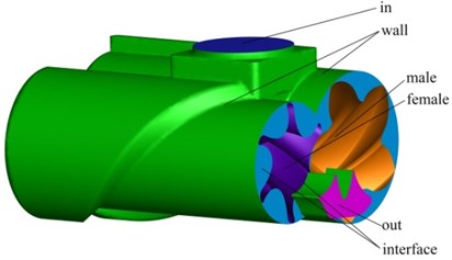
Fig. 5Flow field grid
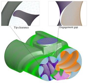
Fig. 6Structural grid
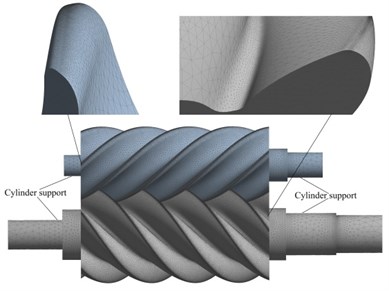
There are a large number of curved surfaces of the compressor’s female and male rotors. Tetrahedral elements are used to divide the internal flow field and structural model of the compressor, and the flow field model is checked by the skewness to avoid the negative volume of the flow field solution process resulting in failure of the solution. After the mesh is divided, the number of grid nodes in the flow field in the compressor is 513667 and the number of units is 2464345, as shown in Fig. 5. The number of screw rotor grid nodes is 1,132,567, and the number of units is 1,134,471, as shown in Fig. 6.
5. Results and discussions
Compressor suction holes are set as pressure inlets, exhaust holes are set as pressure outlets, the boundary conditions of the female and male rotors are set as rotating wall surfaces, and the movement mode is absolute speed movement. The fluid control equation is a time-averaged differential equation. The turbulence model is a dual-equation Realizable - model, which is solved by the SIMPLEC algorithm. The final mass and energy residuals are controlled to be on the order of 10-6 to ensure the results converge. When Fluent established the heat transfer model of the twin-screw compressor, the ambient temperature and the inlet temperature were both taken as 20 °C, and the shell of the compressor was simulated by using virtual wall thickness technology. The material of the compressor casing is gray cast iron HT200, and the screw material is 40Cr. When the structure is solved, a bearing constraint is added to the rotor bearing position, and the shoulder of the exhaust hole bearing is subject to a displacement constraint, and the axial rotation freedom is retained, so that one end of the rotor can swim.
5.1. Temperature field solution results
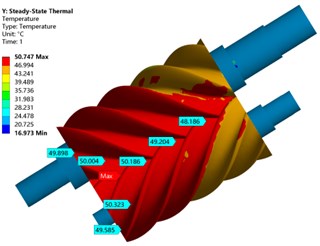
Fig. 7 is a cloud diagram of the temperature distribution of the wall of the male and female rotors in the flow field of the compressor at an exhaust pressure of 0.2 MPa. It can be seen from the figure that after the compressor has been operating for a period of time, the overall temperature of the wall of the female-male rotor is high, the temperature of the wall surface of the screw rotor is distributed in a herringbone shape, and the area A with the smallest volume between the teeth of the female-male rotor has the highest temperature. The temperature from B to E gradually decreases.
Fig. 8 shows the temperature distribution of the female and male rotors of the compressor. It can be seen from the figure that the temperature distribution on the surface of the female and male rotors is the same as the temperature distribution on the rotor wall surface of the internal flow field. Part of the heat is diffused into the rotor through heat conduction, and is transferred from the high-temperature part of the rotor to the low-temperature part. The other part transfers heat through the rotating shaft and the casing, the rotating shaft and the air, and the rotating shaft and the sucked low-temperature gas, and finally realizes the thermal balance of the rotor.
Fig. 7Rotor temperature field distribution
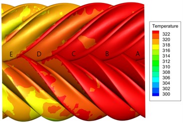
Fig. 8Rotor thermal load distribution
5.2. Thermal-solid coupling analysis
5.2.1. Thermal deformation and thermal stress of screw rotors
Fig. 9 is a deformation cloud diagram of a female-male rotor at an exhaust pressure of 0.4 MPa and a rotation speed of 3000 r/min. The maximum deformation occurs at the end of the male rotor, and the maximum deformation reaches 0.28607 mm. Part of the reason is that the female-male rotor installation method uses one end to swim at one end, The screw rotor located at the exhaust end of the compressor has been in a high temperature environment for a long time, resulting in the thermal expansion of the female-male rotor from the compressor’s exhaust to the suction end, and the deformation of the female-male rotor gradually increases. Another part of the reason is that this position is connected to the motor, which is caused by the large torque during the work. The position of the female-male rotor’s tooth top is more prone to deformation, because when designing the female-male rotor, the rigidity of the tooth top is significantly smaller than the root stiffness. In addition, during the operation of the compressor, the tooth tops of the male and female rotors are in a meshing state for a long time, so it is easy to cause a large deformation of the screw rotor tooth tops.
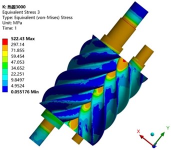
Fig. 10 is a stress cloud diagram of a female-male rotor at an exhaust pressure of 0.4 MPa and a rotation speed of 3000 r/min. The stress distribution of the screw rotor at the root of the rotor is because the size transition of the design of the male and female rotor roots is large, and machining tool marks are easily generated along the tooth root spiral during processing, and stress concentration is easy to occur. During the operation of the compressor, the motor drives the male rotor to collide with the female rotor to perform meshing to complete the compression of the gas. Therefore, a large stress concentration occurs in the male rotor and the meshing area between the male and the female rotor and the mounting bearing position. In addition, during the work of the shaft end where the bearing is installed, friction occurs with the bearing, resulting in greater stress on the shaft segment.
Fig. 9Thermal deformation
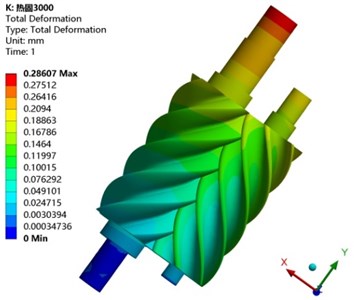
Fig. 10Thermal stress
5.2.2. Influence of different exhaust pressures on thermal deformation and thermal stress of screw rotors
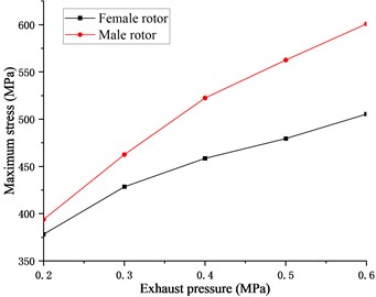
In order to study the deformation law of the twin screw compressor rotor, the deformation and stress changes of the male and female rotors under five different exhaust pressures were analyzed. From Fig. 11, it is analyzed that the maximum deformation of the male and female rotors increases non-linearly with the increase of exhaust pressure. Under low exhaust pressure working conditions, the deformation of the female rotor is larger than that of the male rotor. As the exhaust pressure increases, the deformation of the male rotor is gradually larger than that of the female rotor, and the difference between the two is also significantly increased. It can be seen from Fig. 12 that the maximum stress of the female-male rotor increases non-linearly with the increase of the exhaust pressure. Under the working condition of 0.2 to 0.4 MPa, the increasing tendency of the stress of the female-male rotor is larger than that under the 0.4-0.6 MPa. The maximum stress of the male rotor is greater than the maximum stress of the female rotor, and the stress difference gradually increases as the exhaust pressure increases.
Fig. 11Relationship between deformation and exhaust pressure
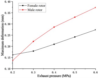
Fig. 12Relationship between stress and exhaust pressure
In order to study the influence of the temperature field generated by the twin screw compressor on the bending deformation of the screw rotor, the path A and path B of the male and female rotors are established in the working section, and the deformation of the male and female rotors is projected on the path AB, as shown in Fig. 13.
Fig. 13Screw rotor path
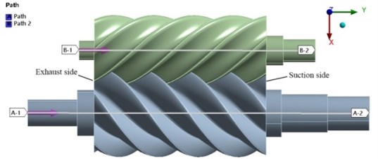
Fig. 14Deformation of screw rotor along path
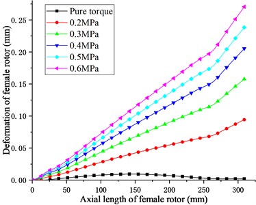
a) Female rotor
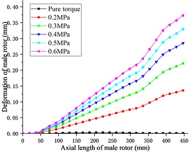
b) Male rotor
Fig. 14 shows the deformation law of the male and female rotors of the twin screw compressor along the path under different exhaust pressures. It can be seen from the figure that the deformation of the female-male rotor is close to zero under the condition of pure torque of the screw rotor. Considering the influence of the temperature field generated by the compressor on the rotor, the deformation of the female-male rotor gradually increases with the increase of the axial length of the rotor, and the thermal deformation of the rotor at the suction side of the compressor is the largest. With the increase of the compressor discharge pressure, the deformation of the male and female rotors gradually increases, but the increase gradually decreases. Therefore, when designing the screw rotor structure, the temperature field generated by the compressor must be checked as the load of the screw rotor.
5.2.3. Influence of different speeds on thermal deformation and thermal stress of screw rotors
Fig. 15 shows the variation of the deformation of the female-male rotor with the rotation speed of the rotor under different exhaust pressures of the twin-screw compressor. It can be seen from the figure that under the condition of pure torque of the screw rotor, the deformation of the female rotor decreases with the increase of the rotation speed, and the maximum deformation of the male rotor increases with the increase of the rotation speed. Considering the coupling effect of the temperature field generated by the compressor and the screw rotor, as the speed increases, the torque acting on the male rotor decreases, and the maximum deformation of the male and female rotors gradually decreases as the rotating speed increases. Therefore, properly increasing the rotation speed can reduce the thermal deformation of the rotor.
Fig. 15Deformation of the rotor at different speeds
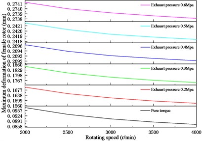
a) Female rotor
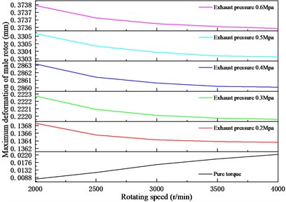
b) Male rotor
Fig. 16Stress law of the rotor at different speeds
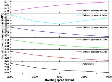
a) Female rotor
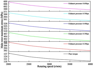
b) Male rotor
Fig. 16 is the variation law of female-male rotor stress with screw rotor speed under different discharge pressure of twin screw compressor. It can be seen from the figure that under the pure torque working conditions of the screw rotor, the maximum stress of the female and male rotors gradually decreases with the increase of the speed. Considering the coupling effect of the temperature field generated by the compressor and the screw rotor, under the working condition of 0.2-0.4 MPa, the maximum stress of the female rotor decreases with the increase of the rotating speed. Under the working condition of 0.5 MPa, the maximum stress of the female rotor decreases first and then increases as the speed increases. Under the working condition of 0.6 MPa, the maximum stress of the female rotor increases with the increase of the speed. Under different exhaust pressures, the maximum stress of the male rotor always decreases with increasing speed. Therefore, choosing the proper working speed can reduce the stress of the screw rotor.
5.3. Thermal modal analysis
In order to study the influence of temperature on the vibration of the screw rotor, Table 2 is the natural frequency of the screw rotor itself and the modal frequency under thermo-solid coupling. It can be seen from the table that the first-order modal frequency of the rotor under thermo-solid coupling is 53.5 % less than its natural frequency, and the second-order modal frequency is increased by 3.5 %. On the one hand, the thermal stress generated by the compressor causes the rotor structure to produce additional geometric stiffness. On the other hand, the temperature field generated by the compressor affects the reduction of the elastic modulus of the rotor material, which eventually causes the modal frequency of the screw rotor to change.
Fig. 17Comparison of rotor vibration modes under different conditions
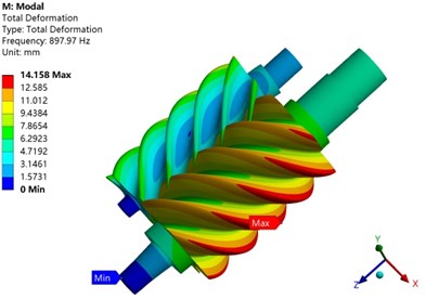
a) First-order natural mode
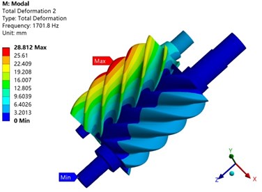
b) Second-order natural mode
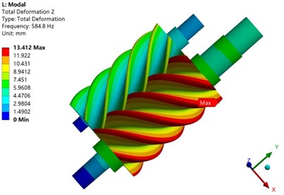
c) First-order mode shapes under coupling
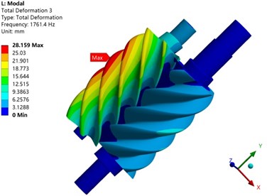
d) Second-order mode shapes under coupling
Fig. 17 is the first two modes of mode inherent in the screw rotor and under thermo-solid coupling. The first-order vibration mode of the rotor is mainly represented by the torsional vibration of the rotor. In both cases, the maximum value of the mode vibration mode occurs at the tooth tip of the male rotor, but the position is different. The second-order vibration mode mainly shows the bending vibration of the rotor, and the trend of the vibration mode is the same in both cases. It shows that the temperature field generated by the compressor has a certain influence on the modal frequency and vibration mode of the screw rotor.
Table 2Comparison of rotor modal frequencies under different conditions
Natural frequency / Hz | Thermo-solid coupling / Hz | Rate of change | |
897.97 | 584.8 | Increase 53.5 % | |
1701.8 | 1761.4 | decrease 3.50 % |
6. Conclusions
Based on the CFD/CSD thermal-solid coupling method, the influence of the twin-screw compressor temperature field on the rotor structural characteristics is analyzed. and the following conclusions are obtained.
The temperature of the compressor screw rotor wall is distributed in a herringbone shape when the compressor is operating stably. The temperature at the discharge side of the compressor is the highest, and the temperature at the suction side is lower.
The temperature field generated by the compressor affects the thermal expansion of the screw rotor and causes a large deformation of the screw rotor near the end of the suction hole. Therefore, a certain gap should be reserved in the axial direction when installing the screw rotor. In addition, there is a large stress concentration in the female-male rotor meshing position and the mounting bearing position.
From the discharge end to the suction end of the compressor, as the axial length of the rotor increases, the deformation of the female-male rotor gradually increases, and as the discharge pressure increases, the deformation of the female-male rotor also gradually increases.
Under the action of the temperature field, the deformation of the female-male rotor decreases with the increase of the speed. The stress of the male rotor decreases with increasing speed at low exhaust pressure and increases with increasing speed at high exhaust pressure. The stress of the female rotor decreases with increasing speed. The modal frequency of the screw rotor is 53.5 % lower than the natural frequency in the first order and increased by 3.5 % in the second order.
References
-
Guo Y. J., Xie J., Zhu S. X., et al. Research status and progress of ultra-low temperature refrigeration plant. Food and Machinery, Vol. 31, Issue 1, 2015, p. 238-243.
-
Xing Z. W., Screw Compressor: Theory, Design and Application. China Machine Press, 2000, p. 8-26.
-
Tang H. N., Li H., Wang S. J. Effect of thermal-solid interaction deformation on the sealing clearance of labyrinth of the BOG compressor. Lubrication Engineering, Vol. 43, Issue 11, 2018, p. 24-27+35.
-
John B., Voorde V. ALE calculations of flow through rotary positive displacement machines. ASME Fluids Engineering Division Summer Meeting, Houston, 2005.
-
Stosic N., Smith I. K., Kovacevic A. Estimation and control of heat transfer in screw compressor rotors. American Society of Mechanical Engineers, Anaheim, 2004.
-
Sauls J. Development of a comprehensive thermodynamic modeling system for refrigerant screw compressors. Proceedings of the International Compressor Engineering Conference, Purdue, 1996.
-
Mustafin T. N., Yakupova R. R., Burmistrova A. V., et al. Analysis of influence of screw compressor construction parameters and working condition on rotor temperature fields. Procedia Engineering, Vol. 152, 2016, p. 423-433.
-
Hsieh S., Hsieh W., Huang C., et al. Numerical analysis of performance, rotor temperature distributions, and rotor thermal deformation of an R314a screw compressor. International Compressor Engineering Conference, Purdue, 2012.
-
Cao F., Gao T. Y., Li S. S., et al. Experimental analysis of pressure distribution in a twin screw compressor for multiphase duties. Experimental Thermal and Fluid Science, Vol. 35, Issue 1, 2011, p. 219-225.
-
Tang Q., Zhang Y. X., Gao Z. Numerical simulation of flow field dynamics characteristics for twin-screw pump. China Mechanical Engineering, Vol. 21, Issue 12, 2010, p. 1453-1457.
-
Wu H. Y., He X. M., Dai J. Research on 3D dynamic simulation analysis of screw compressor by CFD. China Mechanical Engineering, Vol. 24, Issue 24, 2013, p. 3366-3371.
-
Long J., He X. M., Jiang Z. G. CFD simulation analysis and experimental verification of twin screw compressor. Food and Machinery, Vol. 34, Issue 9, 2018, p. 106-110+146.
-
He X. M., Shi G. J., Wu M. P., et al. Exploring and applying a new method of analyzing CFD of twin screw compressor. Mechanical Science and Technology for Aerospace Engineering, Vol. 37, Issue 2, 2018, p. 211-219.
-
Feng B. L. Analysis of Structure and Flow Field Characteristics of Complex Profile Screw Rotor. Shaanxi University of Technology, 2018.
-
Zhou Z. H., Li H. J., Liu Y. L. Synthetical analysis of thermal deformation of rotating parts in symmetric spiral flowmeter. Journal of Naval University of Engineering, Vol. 2, 1998, p. 32-36.
-
Cao F., Chen Z. J., Shu P. C., et al. Screw rotors’ 3-D finite element analysis of heat and force deflection. Journal of Shanghai Jiaotong University, Vol. 10, 2002, p. 1453-1456.
-
Wang X. M., Tian Q. Q., Xiong G. L., et al. Thermal stress analysis based on loading gas axial force on screw rotor meshing contact line. Chinese Hydraulics and Pneumatics, Vol. 7, 2013, p. 59-61.
-
Chen Z. W., Zhang D. Q., Guo J. G., et al. Thermal deformation analysis and optimization for screw vacuum pump rotors. Vacuum, Vol. 53, Issue 3, 2016, p. 48-51.
-
Cui Y. H., Wang Q. S., Wang G. D., et al. Thermal deformation of rotors and casing in operation of screw vacuum-pump. Chinese Journal of Vacuum Science and Technology, Vol. 35, Issue 11, 2015, p. 1291-1294.
-
Wei J., Liang X. L., Sun X. J., et al. Study on the numerical simulation of multi-field coupling characteristics for one novel twin-screw kneader. Journal of Mechanical Strength, Vol. 35, Issue 5, 2013, p. 617-622.
-
Mustafin T. N., Yakupov R. R., Burmistrov A. V., et al. Analysis of the screw compressor rotors’ non-uniform thermal field effect on transmission error. 9th International Conference on Compressors and Their Systems, London, 2015.
-
Hsieh S. H., Shih Y. C., Hsieh W. H., et al. Calculation of temperature distributions in the rotors of oil-injected screw compressors. International Journal of Thermal Sciences, Vol. 50, Issue 7, 2011, p. 1271-1284.
-
Li T. L., Wang J. L., Lei S., et al. Analysis of influence of tooth tip and meshing clearance on flow field characteristics of twin-screw compressor. Journal of Shaanxi University of Technology (Natural Science Edition), Vol. 35, Issue 6, 2019, p. 6-12.
-
Xiao G. F. The Internal Flow Field Modeling, Simulation and Experiment in the Oil-Free Scroll Compressor Chamber. Nanchang University, 2013.
-
Zhang C., Xu Z. L., Liu S., et al. Steam turbine rotor thermal stress calculation with thermo-structural coupled model. Journal of Xi’an Jiaotong University, Vol. 48, Issue 4, 2014, p. 68-72.
-
Xu Q., Feng J. X., Zhang S. C. Effects of different loads on structure stress of “L”-type large-diameter buried pipe network based on fluid-structure-heat coupling. International Communications in Heat and Mass Transfer, Vol. 86, 2017, p. 222-230.
Cited by
About this article

This work was supported by the Science Technology Department Key Project of Shaanxi Province (No: 2017ZDXM-GY-138), the Natural Science Research Project of Shaanxi Province (No: 2020GY-120), Open subject of Shaanxi Key Laboratory of Industrial Automation (No: SLGPT2019KF01-13), and Shaanxi Provincial Department of Education Scientific Research Project (19JK0172).
