Abstract
In this paper, the numerical simulation method of computational fluid dynamics (CFD) is used to establish the flow field model of elbow, including the determination of the applicable gas-solid two-phase flow model and the establishment of the actual basic fluid dynamics equations. After meshing the elbow with ICEM software, the effects of air velocity, bend diameter ratio and other factors on the flow characteristics of the elbow pneumatic conveying are simulated based on FLUENT software. The results show that in the pneumatic conveying with vertical elbows, the flow characteristics of gas-solid two-phase flow have obvious differences with the changes of many factors.
Highlights
- The particle flow characteristics of vertical elbows are studied by numerical simulation
- The pressure drop gradient of the vertical elbow makes a big difference at the elbow
- The pressure drop of the vertical elbow is greatly affected by the particle flow velocity and the bending diameter ratio
1. Introduction
Elbow is one of the typical components in pneumatic conveying system, which has a significant impact on the flow characteristics of gas-solid two-phase flow in conveying pipeline, such as pressure drop, pipe wall wear and material crushing [1]. The flow state of material particles passing through the elbow is very complex. The collision between particles and between particles and pipe wall is easy to form secondary flow, resulting in large pressure drop and energy loss [2]. Therefore, the study of the flow characteristics of two-phase flow in elbow is of great significance to the design and production optimization and the improvement of pneumatic conveying system [3].
In this paper, the gas-solid two-phase flow model of vertical elbow is established by using the numerical simulation method based on computational fluid dynamics (CFD). During the pneumatic conveying process of the vertical elbow, the influence of the bending diameter ratio and air flow velocity on the pressure distribution of the elbow pipe and the flow velocity distribution of solid particles are analyzed. After using ICEM software to generate the model mesh, use FLUENT software to perform 3D finite element analysis.
2. Fundamental equations
For the gas-solid two-phase flow model containing both air and particles, considering the small particle size studied in this paper, the simulation method of Euler two fluid model is used to analyze, that is, both air and particles are regarded as continuous medium. The gas and solid phases follow their own continuity equation and momentum equation respectively, and they are coupled by interaction force [4].
Gas phase continuity equation:
Solid phase continuity equation:
Gas phase momentum conservation equation:
Solid phase momentum conservation equation:
where: is the volume fraction of each item; is the density; is the velocity vector; is the stress tensor; is the gas phase pressure; is the interaction force between gas and solid; is the acceleration of gravity:
where: is the drag coefficient of gas-solid phase, and the drag model proposed by Gidaspow is adopted.
The turbulence model adopts Realizable - model. Compared with the Standard - model, the turbulent viscosity value is related to rotation and curvature, and the term in the dissipation rate equation is modified [5]:
The constants in the equation use default values.
3. Model establishment and numerical simulation
3.1. Physical geometry and mesh
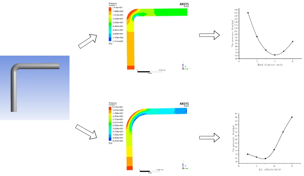
During the pneumatic transportation of vertical bends, the pipes at the inlet section are vertical straight pipes and the pipes at the outlet section are horizontal straight pipes. The geometric model of vertical bends is established by using the three-dimensional software of ANSYS. As shown in Fig. 1, the inner diameter d of the pipe is 30 mm, in which the vertical pipe length L1 is 200 mm, the horizontal pipe length L2 is 200 mm, the bending radius is 30 mm and the bending diameter ratio / is 1. Then, the watershed is meshed by ICEM, Tetrahedral structured grid division is adopted, and the grid is densified near the wall. The number of dividing nodes is 37611 and the number of elements is 106168. The finite element model of elbow is obtained, as shown in Fig. 2.
3.2. Simulation assumption conditions
Due to the complexity of gas-solid two-phase flow in pneumatic conveying system , in order to simplify the calculation model, it is necessary to make some reasonable assumptions about gas-solid two-phase, specifically:
1. Both gas phase and solid phase are continuous incompressible fluids.
2. There is no temperature difference in the flow field and the temperature remains stable.
3. Ignore the collision between particles.
4. The flow in the pipe is regarded as a fully developed turbulent flow.
5. The solid particles are equal in size and are smooth ideal spheres.
6. Only the drag force and gravity caused by the gas-solid velocity difference are considered.
Fig. 1Geometric of vertical bend
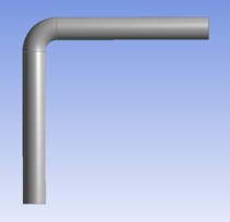
Fig. 2The mesh model of fluid domain

3.3. Calculation method and boundary condition
In this paper, air at room temperature is used as gas phase and main phase, and solid particles are used as secondary phase. Air enters from the inlet of the vertical section of the elbow and flows out from the outlet of the horizontal section. The simulation model uses the Euler method, which is a two-fluid model, to simulate the flow characteristics of the elbow. Because the convergence of first-order discretization is better than that of second-order discretization, the first order upwind scheme is selected as the discretization scheme of turbulence equation [6]. For the pressure velocity coupling, the Simple algorithm is adopted, the residual accuracy is 10-5, 500 iterations, and the results converge.
The physical properties of air and particulate materials are shown in Table 1.
Table 1Detailed material properties
Name | Unit | Value |
Air density | kg/m3 | 1.225 |
Air viscosity | mPa·s | 0.01839 |
Particle average diameter | mm | 0.5 |
Particle density | kg/m3 | 1550 |
The boundary conditions are as follows: 1) Particles are evenly distributed at the inlet, which is the same as the gas velocity; 2) The outlet is set as free flow; 3) Adopt no slip wall; 4) The pressure, momentum, turbulent kinetic energy and turbulent dissipation in the relaxation factor are set to 0.3, 0.7, 0.8 and 0.8 respectively, and the rest remain the default; 5) Acceleration of gravity is 9.81 (m/s2); 6) Steady state calculation.
4. Results and analysis of simulation
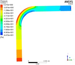
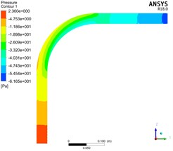
4.1. Distribution of pressure and speed throughout bend
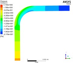
Fig. 3 shows the distribution of pressure and solid velocity in the whole elbow by simulating pneumatic conveying with gas phase velocity of 15 m/s, bend diameter ratio / of 3 and consistent other conditions.
In Fig. 3, the pressure of the entire pipeline is continuously decreasing along the conveying direction. The pressure distribution of the straight pipe at the inlet section and the straight pipe at the outlet section is relatively even, while the distribution at the elbow is very uneven, and the pressure on the outside of the elbow section is significantly greater than it on the inside. And it is not difficult to find that the pressure on the outside of the elbow section is greater than the pressure on the pipe before and after the elbow, while the pressure on the inside of the elbow is smaller than the pressure on the pipe before and after the elbow. This is because the particles are subjected to the action of centrifugal force and collision, which makes the near wall pressure on the outside increase rapidly after entering the elbow and decrease rapidly after leaving the elbow; The near-wall pressure on the inner side of the elbow is exactly the opposite of that on the outer side, showing a trend of first decreasing and then increasing.
Fig. 3Pipeline pressure distribution
4.2. Influence of bend diameter ratio on bend pressure drop
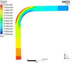
Fig. 4 shows the distribution of pressure in the whole elbow by simulating pneumatic conveying with gas phase velocity of 10 m/s, bend diameter ratio / of 1, 3, 5 and consistent other conditions.
Fig. 4Pressure distribution of bend with different bend diameter ratio
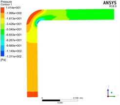
a)/ = 1
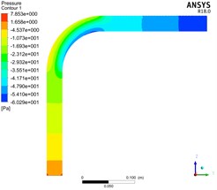
b)/ = 3
c)/ = 5
It can be seen by comparing the filling diagrams of the various isobars in the figure that with the increase of the bend diameter ratio, the pressure distribution in the elbow gradually becomes uniform, and the pressure gradient of the pipeline gradually becomes insignificant. The outside of the elbow section is still larger than the inside, but the pressure difference between the inner and outer sides is gradually reduced.
Fig. 5Pipeline pressure distribution
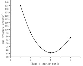
The relationship between the pressure drop of the elbow and the bend diameter ratio is showed in Fig. 5.
According to Fig. 5, when the bend diameter ratio is about 4, there is a minimum pressure drop, and the pressure drop of the elbow shows a trend of first decreasing and then increasing as the bend diameter ratio / increases. The analysis shows that when the bend diameter ratio / is small, the shape of the bend is similar to a right-angle bend, and the particle group collides at the bend, and the speed direction changes rapidly, resulting in congestion, which causes a large energy loss; With the gradual increase of the ratio /, although the degree of bending of the elbow becomes slower, the geometric size of the elbow is increasing, and the interaction area between the particles at the elbow, between the particles and the pipe, and between the particles and the gas changes long, resulting in greater pressure loss.
4.3. Influence of bend diameter ratio on solid velocity
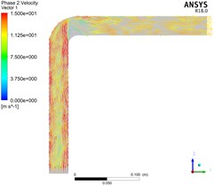
Fig. 6 shows the distribution of solid velocity in the whole elbow by simulating pneumatic conveying with gas phase velocity of 15 m/s, bend diameter ratio / of 1, 3, 5 and consistent other conditions.
In Fig. 6, the smaller the bend diameter ratio / of the elbow, the greater the particle velocity gradient at the elbow. With the continuous increase of the bend diameter ratio /, the particle velocity distribution gradually becomes uniform and the particle velocity gradient at the elbow becomes smaller. Moreover, the distribution of particle velocity at the elbow is very uneven. The particle velocity in the figure shows that the velocity near the wall outside the elbow is higher than that inside the elbow. This is because the particles change direction due to collision and friction when entering the elbow section, the solid velocity will decrease rapidly due to the loss of kinetic energy after particle collision.
Fig. 6Solid velocity distribution of bend with different bend diameter ratio
a)/ = 1
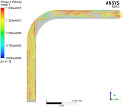
b)/ = 3
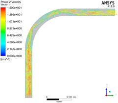
c)/ = 5
4.4. Influence of air velocity on bend pressure drop
Fig. 7 shows the distribution of pressure in the whole elbow by simulating pneumatic conveying with gas phase velocity of 5 m/s, 10 m/s, 15 m/s, bend diameter ratio / of 3 and consistent other conditions.
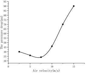
According to Fig. 7, when the bend diameter ratio is constant, the pressure drop of the elbow decreases first and then increases with the gradual increase of the air velocity. Because the particles at the elbow are affected by inertial force and collision, when the air velocity is small, the particles decelerate first and then accelerate at the elbow. However, due to the low speed, the particles gather at the elbow and cause blockage, thereby increasing the pressure drop; When the air velocity is large, the particle velocity will be large at the elbow, the pressure loss caused by collision and friction will become larger, and the area where the particles decelerate first and then accelerate will become larger, resulting in a large pressure drop. The curve of pressure drop at different air velocity is shown in Fig. 8.
According to Fig. 8, the minimum pressure drop air velocity of this model can be 5-10 m/s.
Fig. 7Pressure distribution of bend with different air velocity
a) 5 m/s

b) 10 m/s
c) 15 m/s
Fig. 8Curve of pressure drop at different air velocity
5. Conclusions
The characteristics of two-phase flow in vertical elbow were studied by Fluent numerical simulation. It can be seen from the pressure distribution cloud map of the elbow that the pipeline pressure decreases along the flow direction, and the pressure near the wall outside the elbow is greater than that near the wall inside. With the increase of bend diameter ratio, the pressure drop first decreases and then increases. The smaller the bend diameter ratio, the larger the particle velocity gradient; The larger the bend diameter ratio, the smaller the particle velocity gradient. With the increase of air velocity, the pressure drop of elbow first decreases and then increases.
References
-
Y. Wang, K. Williams, M. Jones, and B. Chen, “CFD simulation methodology for gas-solid flow in bypass pneumatic conveying – A review,” Applied Thermal Engineering, Vol. 125, pp. 185–208, Oct. 2017, https://doi.org/10.1016/j.applthermaleng.2017.05.063
-
A. Sharma and S. S. Mallick, “An investigation into pressure drop through bends in pneumatic conveying systems,” Particulate Science and Technology, Vol. 39, No. 2, pp. 180–191, Feb. 2021, https://doi.org/https://doi.org/10.1080/02726351.2019.1676348
-
N. M. Tripathi, A. Levy, and H. Kalman, “Acceleration pressure drop analysis in horizontal dilute phase pneumatic conveying system,” Powder Technology, Vol. 327, pp. 43–56, Mar. 2018, https://doi.org/10.1016/j.powtec.2017.12.045
-
W. Jia and J. Yan, “Pressure drop characteristics and minimum pressure drop velocity for pneumatic conveying of polyacrylamide in a horizontal pipe with bends at both ends,” Powder Technology, Vol. 372, pp. 192–203, 2020.
-
K. W. Chu and A. B. Yu, “Numerical simulation of the gas−solid flow in three-dimensional pneumatic conveying bends,” Industrial and Engineering Chemistry Research, Vol. 47, No. 18, pp. 7058–7071, Sep. 2008, https://doi.org/10.1021/ie800108c
-
X. Li, F. Yan, P. Tu, Y. Chen, Y. Zheng, and R. Zhu, “Particle dynamics analysis in bend in a horizontal-vertical pneumatic conveying system with oscillatory flow,” Advanced Powder Technology, Vol. 32, No. 3, pp. 637–645, Mar. 2021, https://doi.org/10.1016/j.apt.2020.12.031
About this article

