Abstract
To predict and improve the surface quality of complex curved surface structure precision machined by solid-liquid two-phase abrasive flow, this paper takes the S-shaped elbow as the research object, carries out the numerical simulation of abrasive flow polishing process of S-shaped elbow based on large eddy simulation method, analyzes the velocity distribution of abrasive flow, turbulent energy, wall shear force nephogram and trace diagram of abrasive flow in the S-shaped elbow under different inlet speed and abrasive concentration conditions. It is found that the values of velocity, turbulent energy and wall shear force on the inner side of the elbow and the outlet pipe are relatively large, indicating that the polishing quality at these positions is better. Increasing the inlet velocity can improve the effectiveness of abrasive flow polishing, and properly increasing the abrasive concentration can improve the surface uniformity of polished wall. It can provide a theoretical basis for promoting the continuous improvement of abrasive flow precision machining technology.
1. Introduction
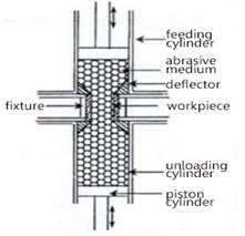
With the rapid development in modern industry, the application of elbow parts in production and life is becoming more and more extensive, the surface quality of elbows has also higher requirements. The abrasive flow polishing technology uses abrasives with a certain concentration as a carrier, and bends the abrasive through the surface of the workpiece under the action of squeezing force. So the surface of the workpiece is polished, deburred, and rounded, it can realize ultra-precision machining [1, 2]. This polishing technology is not limited to the shape and size of the workpiece, and is particularly suitable for the ultra-precision machining of micro-holes, complex internal cavity structures and uneven surfaces, so the complex S-elbow of the internal cavity can achieve better polishing effect and get the ideal processing effect [3]. Fig. 1 shows the principle diagram of abrasive flow polishing.
Large eddy simulation (LES), as a method of studying turbulence, is often used in the numerical simulation of abrasive flow processing. The basic idea of LES is to solve the Navier-Stokes equation, directly solve the large-scale vortex, and solve the small-scale vortex by constructing a model. The distinction between large-scale and small-scale vortices is achieved by filtering. The model constructed during the solution process is also called the sub-grid scale model, and the key to achieving LES is to construct a closed mode of sub-grid stress [4, 5].
In this paper, the LES method is used to numerically simulate the process of abrasive flow polishing S-shaped elbow, analyze the effect of different inlet speed and abrasive concentration on the polishing effect, and analyze the factors affecting the surface quality of abrasive flow polishing S-shaped elbow to provide a theoretical basis for actual production and processing.
Fig. 1Schematic diagram of abrasive flow polishing
2. S-shaped elbow model
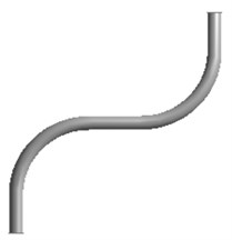
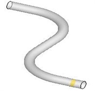
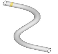
This article is based on the existing theory of abrasive flow processing and related papers [6-8]. S-shaped elbow is 100 mm in length, 70 mm in width, 26 mm in radius, 8 mm in outer diameter, and 5 mm in inner diameter. Fig. 2 is a front view of an S-shaped elbow, and Fig. 3 is a three-dimensional model of an S-shaped elbow.
Fig. 2Two-dimensional diagram of S-shaped elbow
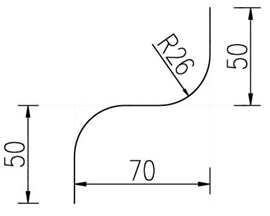
Fig. 3Three-dimensional model of S-shaped elbow
3. Simulation and analysis
3.1. Simulation and analysis at different inlet speeds
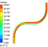
Based on the existing research on abrasive flow, the Kinetic-Energy Transport (KET) model in the LES method is adopted. The solid phase of the solid-liquid two-phase abrasive flow is silicon carbide with a density of 3170 kg/m3, and the liquid phase is oil with a density of 1260 kg/m3. This article chooses velocity and pressure inlet boundary conditions and free outlet boundary conditions. Firstly, set the abrasive concentration to 30 %, analyze the velocity cloud diagram, turbulent energy cloud diagram and wall shear force cloud diagram when the inlet velocity boundary conditions are 30 m/s, 40 m/s, 50 m/s and 60 m/s, and explore the quality performance of abrasive flow polishing S-shaped elbow. When the abrasive concentration is 30 %, the velocity cloud diagrams at different inlet velocities is shown in Fig. 4.
It can be seen from the Fig. 4 that when the inlet velocity gradually increases, the velocity change in the tube also becomes obvious. The abrasive speed first reaches the maximum near the inside of the elbow, and then impacts the outside of the elbow, the speed becomes larger, and then flows along the inside of the outlet of the elbow, the speed reaches the maximum, and the abrasive reaches the elbow when exiting the road, the speed of the right pipe is greater than the speed of the left pipe. It can be drawn that polishing quality becomes better when the inlet speed is increased, the polishing quality on the inside of the elbow is higher than that on the outside, and the polishing quality on the right side of the elbow outlet is better than that on the left.
Fig. 4Cloud diagram of velocity distribution for different inlet velocity conditions
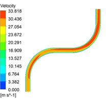
a) Inlet speed is 30 m/s
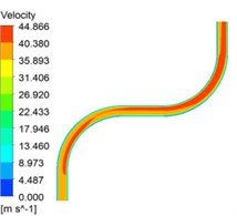
b) Inlet speed is 40 m/s

c)Inlet speed is 50 m/s
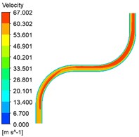
d) Inlet speed is 60 m/s
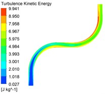
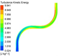
Fig. 5Turbulent energy cloud at different inlet velocities
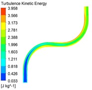
a) Inlet speed is 30 m/s
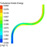
b) Inlet speed is 40 m/s

c)Inlet speed is 50 m/s
d) Inlet speed is 60 m/s
It can be found from the Fig. 5 that as the inlet velocity increases, the turbulent flow energy also increases, and the polishing effect on the S-shaped elbow is better. The turbulent flow energy at the inlet is smaller than that at the outlet. At the same time, the turbulent flow energy measured in the elbow is relatively large, and the turbulent energy inside the elbow of the S-shaped elbow is smaller than that inside the elbow. The inner quality of the S-shaped elbow polished by abrasive flow is better than other places, and the polishing effect on the inner side of the outlet of the elbow is better than that at the entrance.
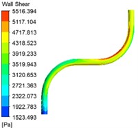
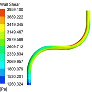
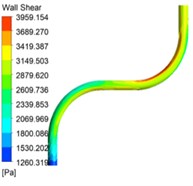
Fig. 6Cloud shear wall at different inlet velocities
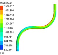
a) Inlet speed is 30 m/s
b) Inlet speed is 40 m/s

c)Inlet speed is 50 m/s
d) Inlet speed is 60 m/s
Fig. 6 is a wall shear force cloud diagram with different inlet speeds. It can be seen that the wall shear force increases with the increase of the inlet velocity. The wall shear force at the entrance is smaller than that at the outlet, and the wall shear force at the inner surface of the elbow inlet is greater than that of the elbow outlet The wall shear force on the inner surface is small. The same conclusion as above can be obtained. It is that properly increasing the inlet speed can improve the quality of the abrasive flow polishing S-elbow. The inner surface quality of the polished S-elbow is higher than the outer surface quality, and the polishing effect of the outlet inner bend surface is better than the inside surface of the entrance.
3.2. Simulation and analysis under different abrasive concentration conditions
Under the condition of 50 m/s inlet velocity, S-shaped elbows are numerically simulated with 10 %, 20 %, 30 %, and 40 % abrasive concentrations.
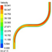
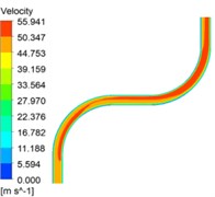
Fig. 7The velocity distribution clouds of different abrasive concentrations
a) 10 % concentration
b) 20 % concentration
c) 30 % concentration

d) 40 % concentration
Fig. 7 is a velocity distribution cloud diagram of different abrasive concentrations. It can be seen that as the abrasive concentration becomes larger, the movement process of the abrasive flow is relatively stable, but the difference in the velocity of the inner and outer walls becomes smaller. The speed of the elbow inlet is less than that of the elbow outlet; the speed of the inside of the elbow is greater than that of the outside of the elbow; the speed change near the elbow outlet is more obvious, and the speed change on the right side of the elbow outlet is greater than the left side. This shows that when the abrasive flow polishes the S-shaped elbow, the quality of the inside of the polished elbow is better than the quality of the outside, and the polishing effect of the elbow outlet is better than that of the elbow inlet.
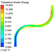
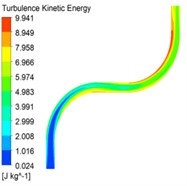
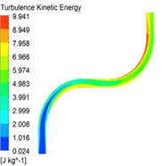
Fig. 8Turbulent flow cloud of different abrasive concentrations
a) 10 % concentration
b) 20 % concentration
c) 30 % concentration
d) 40 % concentration
Analysis of Fig. 8 shows that the increase of the turbulent flow energy with the increase of the abrasive concentration is not obvious, but the stability of the turbulent flow energy in the S-shaped elbow is improved. As the abrasive moves in the tube, the turbulent flow energy gradually becomes larger; the turbulent flow energy on the inner surface of the elbow is the largest, and the turbulent flow energy on the inner surface at the outlet of the elbow exhibits the largest trend. These phenomena indicate that the effect of abrasive flow polishing on the surface of the wall of the S-shaped elbow is better. The processing quality of the outlet of the elbow is higher than the quality of the inlet of the elbow. The increase in the abrasive concentration can further improve the uniformity of the surface quality of the inner wall of the S-shaped elbow.
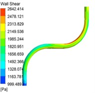
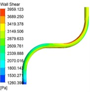
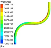
Fig. 9Cloud shear wall clouds with different abrasive concentrations
a) 10 % concentration
b) 20 % concentration
c) 30 % concentration
d) 40 % concentration
Fig. 9 is a cloud diagram of the wall shear force with different abrasive concentrations. It can be seen that the wall shear force decreases with increasing abrasive concentration, but the change is not obvious. The wall shear force is the smallest in the inlet pipe, and then slowly increases. The wall shear force on the inner surface of the elbow is greater than the outer surface of the elbow and other places. The wall shear force is the largest on the inner surface of the outlet elbow, indicating that the effect of abrasive flow polishing on the S-shaped elbow reaches the best on the inner surface of the elbow. By analyzing the shear force on the wall surface of the bent pipe, it can be found that the increase in the abrasive concentration has a positive effect on the processing of the abrasive flow polishing S-shaped elbow, which can further improve the uniformity of the surface quality of the pipe wall.
3.3. Fluid trace analysis quality of the pipe wall.
The trajectory refers to the trajectory of the path along which the flow point moves at various times, and can represent the state of fluid movement at a certain position in space. This section will analyze the movement traces of the inlet cross section, middle cross section and outlet cross section of the S-shaped elbow when the abrasive concentration is 30 % and the inlet pressure velocity is 30 m/s. The cut cross-section is shown in Fig. 10.
Fig. 10Schematic diagram of S-shaped elbow
a) Inlet cross section
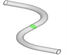
b) Mid section cross section
c) Outlet cross section
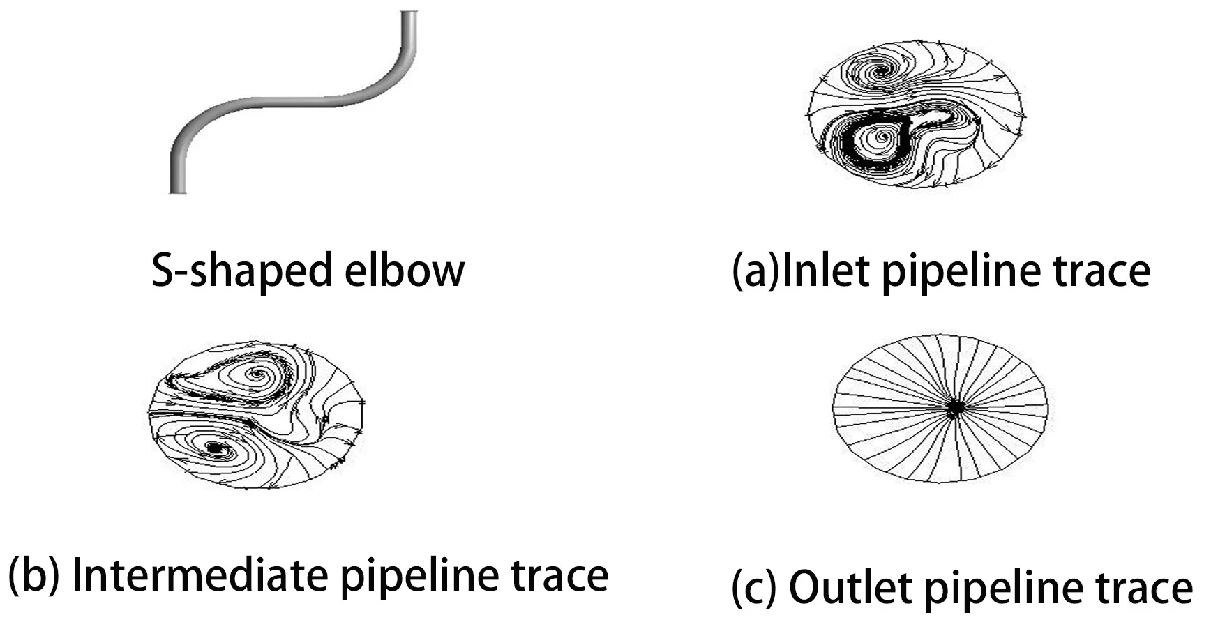
Fig. 11Fluid trace
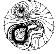
a) Inlet pipeline trace

b) Intermediate pipeline trace
c) Outlet pipeline trace
Fig. 11 is a fluid trace of three cross-sections cut. Analyze the flow of abrasive particles and the distribution law of vortex in S-shaped elbow. It can be seen from the Fig. 11(a) that there are two vortices in in the motion path of the abrasive particle flow, the flow directions of the two vortices are opposite, and the vortices below are more dense, it can be concluded that the inner surface of the inlet of the S-shaped elbow is more abrasive flow. It can be seen from Fig. 11(b) that the flow directions of the two vortices are also opposite, the velocity of the upper side pipe is greater than that of the lower side. The upper vortex is more dense when presented in the trace diagram, and the abrasive flow on this side is better. From Fig. 11(c), we can find that when the abrasive particles just flow out, the speed is relatively uniform. As the abrasive particles continue to flow, its movement state gradually becomes chaotic, and the speed of the pipe on the right side becomes larger; Combined with the velocity cloud at this position, it can also be seen that the velocity increases from a uniform distribution to the right, proving that the polishing quality of the abrasive flow on the right surface of the elbow outlet is better than that on the left.
4. Conclusions
1) Through the large-eddy numerical simulation analysis of the S-shaped elbow, it can be concluded that as the inlet velocity of the abrasive flow increases, the velocity, turbulent flow energy and wall shear force in the pipe increase, and the polishing effect on the bend pipe become better. It can be proved that the inlet velocity is basically positively related to them. But there are also differences in the polishing effect of each position. The polishing quality of the outlet of the elbow is higher than the inlet of the elbow, and the polishing quality of the inner surface is higher than that of the other positions, the polishing effect of this position is the most ideal.
2) Analysis of the abrasive flow polishing S-shaped elbow under different abrasive concentration conditions can be found that the change in abrasive concentration does not significantly affect the motion intensity. Increasing the abrasive flow concentration can enhance the polishing effect of the S-shaped elbow and ensure processing consistency of effect. Therefore, a higher concentration abrasive flow polishing liquid should be used when performing abrasive flow polishing.
3) Analysis of the fluid trace of the abrasive flow polishing S-shaped elbow can be found that two vortices with opposite flow directions will be generated in elbow, and the vortex on the inner surface will be denser. The movement trace of the pipe outlet changes from stable to turbulent, that is, the speed changes suddenly from the uniform distribution to the right. Further verifying that the abrasive particle flow polishing the inner surface of the S-shaped pipe will be better, and the right surface polishing effect of the pipe outlet is better than the left.
References
-
Jain V. K., Adsul S. G. Experimental investigations into abrasive flow machining (AFM). International Journal of Machine Tools and Manufacture, Vol. 40, Issue 7, 2000, p. 1003-1021.
-
Yadav Pawan, Jayswal S. C. Experimental investigations into abrasive flow machining (AFM). Materials Today: Proceedings, 2019.
-
Gao Hang, Wu Mingyu, Fu Youzhi, Guo Dongming Development of theory and technology in fluid abrasive finishing technology. Journal of Mechanical Engineering, Vol. 51, Issue 7, 2015, p. 174-187.
-
Zhao Jinghe, Yin Yanlu, Li Junye, Pan Yuxue Numerical simulation of large eddy flow in common rail pipe mill. Machine Design and Research, Vol. 32, Issue 3, 2016, p. 106-109+128.
-
Ghosal S., Lund T. S., Moin P., et al. A dynamic localization model for large-eddy simulation of turbulent flows. Journal of Fluid Mechanics, Vol. 286, Issue 297, 1995, p. 229-255.
-
Liu Guosong, Zhang Xinming, Liu Hongbo, Hu Jinglei, Li Junye Effects of different inlet velocity on the polishing quality of abrasive flow machining. Vibroengineering Procedia, Vol. 24, Issue 6, 2019, p. 84-88.
-
Li Junye, Zhang Hengfu, Wei Lili, Zhang Xinming, Xu Ying, Xu Chengyu Formation mechanism and quality control technology for abrasive flow precision polishing vortex: large eddy simulation. The International Journal of Advanced Manufacturing Technology, Vol. 105, 2019, p. 2135-2150.
-
Liu Hongbo, Li Junye, Yan Wenduan, Hu Jinglei, Zhang Xinming, Wang Xinpeng Numerical simulation of the variable diameter pipe based on abrasive flow machining. Vibroengineering Procedia, Vol. 23, Issue 4, 2019, p. 149-153.
About this article

The authors would like to thank the National Natural Science Foundation of China No. NSFC 51206011 and U1937201, Jilin Province Science and Technology Development Program of Jilin province No. 20200301040RQ, Project of Education Department of Jilin Province No. JJKH20190541KJ, Changchun Science and Technology Program of Changchun City No. 18DY017.
