Abstract
The Eulerian-Eulerian method is used to numerically simulate herringbone teeth using the precision machining technique of abrasive flow. The effects of inlet velocity and abrasive concentration factors on abrasive flow machining are investigated separately for numerical analysis to reveal the effects of dynamic pressure and wall shear on abrasive flow machining under different machining parameters. The simulation results show that increasing the inlet velocity can improve the processing efficiency and the processing effect of abrasive flow processing. Increasing the abrasive concentration increases the processing cost and predicts a weakening of the abrasive flow, allowing for the use of lower concentrations of abrasive flow for actual processing.
Highlights
- Numerical simulation of herringbone teeth using abrasive flow precision machining techniques
- Numerical analysis of different entrance speeds on herringbone gear machining
- Numerical analysis of different abrasive concentrations on the machining of herringbone gears
1. Introduction
Herringbone tooth planetary transmission is widely used in the transmission field of armament equipment, shipbuilding heavy industry, aviation and automobile because of the advantages of reliable work, smooth transmission, large load-bearing capacity, compact structure, high transmission efficiency, high degree of overlap and small axial force [1]. Herringbone gears have a certain helix angle, traditional finishing processes such as grinding, grinding and hand polishing can achieve the accuracy requirements of mechanical parts, but their efficiency is low and the cost is high, abrasive flow machining as a new surface treatment method, because of its high processing accessibility to the internal surface of through-hole type parts and complex curved surfaces have a good surface treatment effect [2].
Abrasive flow polishing is a flexible finishing technique using polymeric soft abrasives as the processing medium and the overall quality of the process is not dependent on the skill of the operator [3]. Since the introduction of abrasive flow polishing technology, many scholars at home and abroad have explored the removal mechanism and the laws of the processing process of abrasive flow processing technology. Wang [4] et al. proposed a new method to achieve uniformity in the surface finishing of elliptical hole cavities by placing similar die cores, which provides an important reference for high-quality precision machining of elliptical holes, in response to the problem of inconsistency in the surface finishing quality of elliptical hole cavities due to changes in the radius of curvature of the surface. Li [5-6] et al. studied the process characteristics of complex flow channels with shaped internal surfaces and S-shaped elbows with side holes for abrasive flow processing based on the large eddy simulation method, providing theoretical guidance and data support for practical production. Shi Yan [7] et al. used the abrasive flow polishing technique to polish the inner surface of SLM additive manufacturing microfluidic channels and investigated the effect of abrasive flow on the surface quality of microfluidic channels and the shape accuracy of inner holes under different polishing pressures. Kumar Raman [8] et al. demonstrated the efficiency and economy of abrasive flow polishing by studying the effect of different process parameters on final surface roughness, percentage improvement in surface roughness and polishing time in comparison with conventional polishing. Huang [9] et al. calculated the transient flow gas phase field and the motion, dynamics and collision characteristics of sand, and used the Archard wear model to calculate the amount of wear on the sandblaster and analyse the wear pattern.
In this paper, the Eulerian method will be used to study the processing law of herringbone gears with different parameters by numerical simulation, and the processing effect of abrasive flow processing will be discussed concerning the numerical simulation results.
2. The basic equation for abrasive flow
Equations of mass and momentum:
where is the density; is the velocity; is the stress tension; is the volume force.
The - model and the mixture model are used as the turbulence and multiphase flow models for this paper. - turbulence model expressions are as follows:
where, is the turbulent kinetic energy; is the dissipation rate of turbulent kinetic energy; is the laminar viscosity coefficient; is the turbulent viscosity coefficient, is a constant, is the turbulent kinetic energy generated by the laminar velocity gradient; is the turbulent kinetic energy generated by buoyancy; , , , , are model empirical coefficients.
The expression for a multiphase flow model of a mixture is:
where is the mass-averaged velocity; is the density of the mixture; is the number of phases; is the bulk force; is the average viscosity of the mixed phase; is the drift velocity.
3. Numerical simulation analysis of abrasive flow processing
The object of study in this paper is a herringbone gear with a modulus of 2.5 and a tooth count of 15 as shown in Table 1.
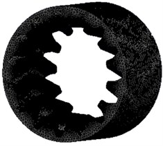
According to the basic parameters, the 3D model is drawn, and the tetrahedral structure is used to mesh the 3D model. The 3D structure schematic and mesh structure are shown in Fig. 1.
For the flow channel structure, the pressure-based solver is used to solve the flow with the abrasive particle as a solid-liquid two-phase flow, with the liquid phase being aviation paraffin and the solid phase being SiC. The mixture model is activated and the k-ε turbulence model is used to describe the liquid phase motion. The SIMPLEC algorithm is chosen to solve the flow field, which gives better convergence results for incompressible fluids and non-constant flows.
Table 1Basic parameters of herringbone gears
Name | Parameter value | Name | Parameter value |
Number of teeth | 15 | Modulus / mm | 2.5 |
Pressure angle | 20° | Helix angle | 20° |
Addendum height coefficient | 1 | Tooth width / mm | 30 |
Addendum circle diameter / mm | 44.9 | Tooth root circle diameter / mm | 33.7 |
Fig. 1Flow channel meshing and 3D structure

3.1. Numerical analysis of inlet velocities on herringbone gear machining
As the machining process is consistent within the runners, the results are consistent across the different tooth flutes. A set of tooth grooves, tooth tops and root areas were extracted for analysis.
3.1.1. Numerical analysis of the dynamic pressure at different inlet velocities
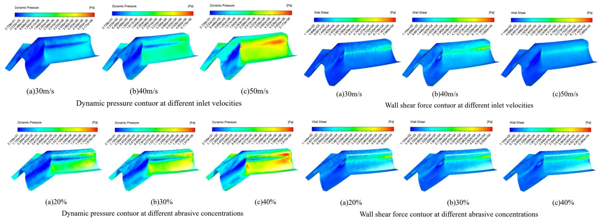
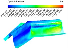
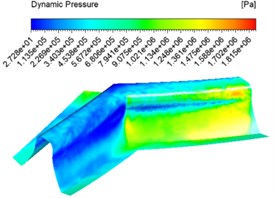
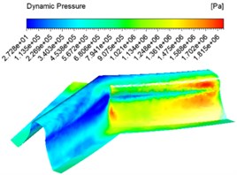
The inlet velocity was set to 30 m/s, 40 m/s, 50 m/s and an abrasive concentration of 30 % for numerical analysis, and different dynamic pressure contuor were obtained as shown in Fig. 2.
Fig. 2Dynamic pressure contuor at different inlet velocities
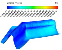
a) 30 m/s
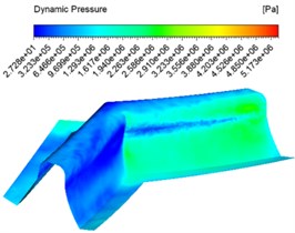
b) 40 m/s
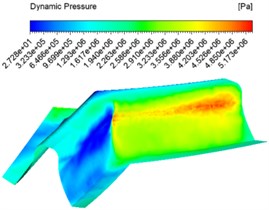
c) 50 m/s
Fig. 2 shows the dynamic pressure cloud at the inlet at different speeds, with the abrasive inlet on the right and the abrasive outlet on the left. It can be seen from the graph that the pressure at the inlet increases slowly at the same inlet speed and then decreases instantly when the abrasive reaches the junction of the two teeth. This is because when the abrasive reaches the junction of the two teeth, the contact force between the abrasive and the wall of the tooth surface is at its maximum. With the abrasive flow, the abrasive particles flowing along the tooth grooves do not rub against the wall surface, and thus the dynamic pressure at the table becomes smaller. The faster the entrance speed at different speeds, the higher the pressure. The pressure at the junction of the tooth surface and the tooth root becomes significantly higher, and the processing effect becomes better.
3.1.2. Numerical analysis of wall shear forces at different inlet velocities
The same inlet velocities of 30 m/s, 40 m/s, 50 m/s and an abrasive concentration of 30 % were also set for the numerical analysis and different wall shear contuor were obtained as shown in Fig. 3.
Fig. 3Wall shear force contuor at different inlet velocities
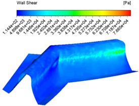
a) 30 m/s
b) 40 m/s
c) 50 m/s
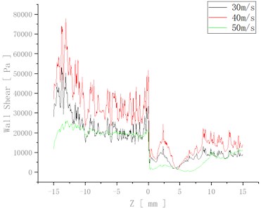
Fig. 3 shows that the overall shear force at the same speed inlet changes from shallow to dark, which indicates that the shear force changes from large to small, with the maximum shear force at the junction of the tooth root and tooth surface. The overall difference in shear force between the tooth surface at different speed inlets is not significant, but increases and then decreases at the junction between the tooth surface and the tooth root as the speed increases.
In order to visualise the change in wall shear at different speeds, the change in wall shear is plotted in Fig. 4.
At 50 m/s the shear force variation fluctuates the least, which indicates the most uniform and best processing in this case.
Fig. 4Variation of wall shear at different speeds
3.2. Numerical analysis of abrasive concentration on herringbone gear machining
3.2.1. Numerical analysis of the effect of different abrasive concentrations on dynamic pressure
The numerical analysis was carried out with the abrasive concentration set at 20 %, 30 %, 40 % and an inlet speed of 30 m/s, and different dynamic pressure contuor were obtained as shown in Fig. 5.
Fig. 5 shows that at the same concentration the dynamic pressure increases from the inlet and then gradually decreases, reaching the junction of the two tooth surfaces where the pressure instantly decreases. This is because when a certain concentration of abrasive enters the tooth groove, the abrasive particles collide with the wall, the flowing abrasive from the middle part of the tooth groove increases the dynamic pressure because it does not participate in the collision of the wall, and reaches the junction of the two tooth surfaces where a large amount of abrasive collides and consumes kinetic energy, the dynamic pressure decreases. At different concentrations, the dynamic pressure increases as the concentration increases, and the dynamic pressure increases significantly at the junction between the tooth surface and the root of the tooth.
Fig. 5Dynamic pressure contuor at different abrasive concentrations
a) 20 %
b) 30 %
c) 40 %
3.3. Numerical analysis of different abrasive concentrations on wall shear forces
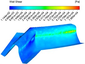
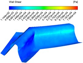
The same abrasive concentration settings of 20 %, 30 %, 40 % and an inlet velocity of 30 m/s were used for the numerical analysis and different wall shear force contuor were obtained as shown in Fig. 6.
Fig. 6Wall shear force contuor at different abrasive concentrations
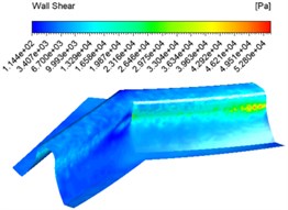
a) 20 %

b) 30 %
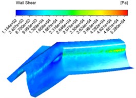
c) 40 %
Fig. 6 shows that the overall shear force varies from shallow to dark at the same concentration inlet, which indicates that the shear force varies from large to small, with the maximum shear force at the junction of the tooth root and tooth surface. The overall difference in shear force between the different concentrations of shear force is not significant.
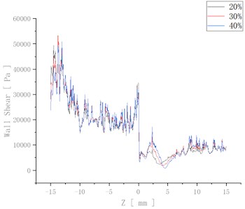
In order to visualise the change in wall shear at different speeds, the change in wall shear is plotted in Fig. 7.
The wall surface shear increases somewhat when the abrasive concentration increases from 20 % to 30 %. At the same time, the wall shear at the inlet wall surface decreases slightly, and the wall shear at the outlet wall surface increases when the concentration is increased from 30 % to 40 %. This is because as the abrasive concentration increases, the viscosity of the fluid increases. Although the number of particle-wall collisions increases, the kinetic energy transferred per collision decreases, thus predicting a weaker abrasive flow processing effect at higher concentrations.
Fig. 7Variation in wall shear at different concentrations
4. Conclusions
1) A solid-liquid two-phase flow model for abrasive flow grinding herringbone gears was established, and numerical simulation studies of abrasive flow under different conditions were carried out to obtain the influence of inlet flow rate and abrasive concentration on the dynamic pressure distribution and wall shear force inside the tube.
2) The inlet flow rate is the main cause of pressure changes in the fluid at the wall, and increasing the flow rate can improve processing efficiency and processing results.
3) Abrasive concentration also affects the pressure of the fluid at the wall. The increase in dynamic pressure and wall shear is not significant when the abrasive concentration is increased in the range of 20 % to 40 %. However, increasing the abrasive concentration increases the cost of processing and also increases the risk of clogging of the circulation device for two-phase fluids and increased wear, which can be practically achieved using a low concentration of abrasive grain flow.
References
-
Bu Zhonghong, Liu Geng, and Wu Liyan, “Natural characteristics analysis on herringbone planetary gear trains with slide bearing support,” Journal of Mechanical Engineering, Vol. 47, No. 1, pp. 80–88, Jan. 2011.
-
J. Guo, L. Gui, W. Hou, J. Qu, Z. Zhu, and J. Li, “The quality control technology of inner surface of valve sleeve in abrasive flow machining,” The International Journal of Advanced Manufacturing Technology, Vol. 121, 2022.
-
W. Haiquan, “Study on prediction of surface roughness for abrasive flow machining,” Journal of Mechanical Engineering, Vol. 58, No. 15, pp. 188–197, 2022.
-
Hongchao Yin, Xiao Liu, Zhende Qu, and Lin Mu, “Numerical simulation of abrasive flow machining in multi-angle elbows,” China Mechanical Engineering, Vol. 32, No. 11, pp. 1299–1306, 2021.
-
J. Li, J. Qu, H. Lu, X. Zhang, W. Zhao, and X. Li, “Effectiveness analysis of abrasive flow polishing S-shaped elbow with side holes based on large eddy simulation,” The International Journal of Advanced Manufacturing Technology, Vol. 115, No. 11-12, pp. 3887–3906, Aug. 2021, https://doi.org/10.1007/s00170-021-07384-w
-
Chengyu Xu et al., “Large eddy simulation studies of two-phase flow characteristics in the abrasive flow machining of complex flow ways with a cross-section of cycloidallobes,” International Journal of Hydromechatronics, Vol. 5, No. 2, pp. 136–166, 2022.
-
Shi Yan, Guo Zhi, Liu Jia, and Ma Zhi-Qian, “Polishing process and mechanism of abrasive flow on inner surface of microchannel by SLM additive manufacturing,” Surface Technology, Vol. 50, No. 9, pp. 361–369, 2021.
-
R. Kumar et al., “Hand and abrasive flow polished tungsten carbide die: optimization of surface roughness, polishing time and comparative analysis in wire drawing,” Materials, Vol. 15, No. 4, p. 1287, Feb. 2022, https://doi.org/10.3390/ma15041287
-
S. Huang, J. Huang, Z. Hui, M. Li, and W. Ye, “Wear calculation of sandblasting machine based on EDEM-FLUENT coupling,” International Journal of Hydromechatronics, Vol. 1, No. 4, p. 447, 2018, https://doi.org/10.1504/ijhm.2018.097295
About this article

The authors would like to thank the Science and technology development plan project of Jilin province No. 20220201036GX and 20210201057GX.
The datasets generated during and/or analyzed during the current study are available from the corresponding author on reasonable request.
The authors declare that they have no conflict of interest.
