Abstract
The SST - method is used to numerically simulate the effect of the inlet pressure and processing method on the machining of a three-way hole, revealing the effect of dynamic pressure and wall shear on the machining of the grain flow with different processing parameters. The simulation results show that increasing the inlet pressure and choosing a suitable processing method can improve the processing effect of abrasive flow processing.
Highlights
- Numerical simulation analysis of cross holes with different machining parameters
- Dynamic pressure and wall shear analysis at different pressure inlets
- Dynamic pressure and wall shear analysis for different processing methods
1. Introduction
With the progress and development of our industry, there are higher requirements for the surface roughness of complex parts cross-holes within the aviation, medical and automotive sectors. Burrs in machining mechanical parts can reduce the efficiency of machinery, increase wear and tear and reduce service life. In the 1960s, NASA proposed a two-phase flow polishing process, abrasive flow machining (AFM), to remove internal burrs from aerospace hydraulic valve bodies and other devices [1].
Abrasive grain flow is an effective surface machining method that is invariably invisible and non-porous. As a result, good profiling contact can be formed with the machined surface, which is a unique advantage in machining curved and anisotropic surfaces [2]. Abrasive Flow Machining is a flexible finishing technology using viscoelastic abrasive media, which reduces the ripples and surface roughness of the workpiece surface by squeezing through the surface of the workpiece, removing the material from the surface to be machined with micro-force micro-removals, achieving deburring, deburring, chamfering and polishing processes. The current industrial situation requires higher productivity, which is met by advanced material removal processes, namely abrasive flow machining (AFM), where the inner surface of the workpiece is machined to a higher level of precision with the help of an abrasive-containing medium [3].
In recent years, the theory and technology of abrasive flow processing have been improved. Fu et al. [4] constructed a simulation model based on different abrasive types and derived from the continuous medium theory that the abrasive particle size has less influence on the rheological characteristics under the same abrasive volume fraction, and the abrasive rheological characteristics are in line with the power law model. Wang [5] et al. proposed a surface roughness prediction model based on abrasive flow polishing for the problems of high cost, low efficiency and poor surface quality controllability of complex impeller/disc blade profile finishing. Liu [6] et al. used the Preston equation as the basis for evaluation, analyzed the influence law of abrasive particle size and fluid medium on the polishing effect, and obtained the trend of the polishing degree of the inner wall of the circular tube along the axial direction of the circular tube under different abrasive flow parameters. Cheng [7] et al. investigated the grinding mechanism of abrasive flow machining and improved the Preston equation. The improved Preston equation helps to optimize the abrasive flow machining process and better predict virtual surface roughness and material removal rates. Mohseni [8] et al. proposed a consistent numerical method capable of dealing with fluid-structure interface problems as well as surface erosion to simulate soft abrasive flow processing and contribute to a more in-depth understanding of the process. Li [9-11] et al. studied the process characteristics of abrasive flow processing with shaped cross sections. Huang [12] et al. calculated the transient flow gas phase field and the motion, dynamics and collision characteristics of sand and used the Archard wear model to calculate the amount of wear on the sandblaster and analyze the wear pattern.
The burr and machining quality at the cross-hole of the tee bore affects the operational performance. This paper investigates the influence of different parameters on the machining quality of the wall and edge of the cross-hole for the tee bore with cross-hole and reveals the impact of dynamic pressure and wall shear force on the wall machining during the processing of abrasive flow.
2. Abrasive particle flow mechanics model
2.1. The basic equation for abrasive flow
Equations of mass and momentum:
where, is the density; is the velocity; is the stress tension; is the volume force.
2.2. Turbulent and multiphase flow models
The SST - model combines the - and - models, using different turbulence models in different Reynolds number regions, with higher simulation accuracy for the flow field. The SST - model and the mixture model are used as the turbulence and multiphase flow models for this paper, respectively. The expressions for the SST - turbulence model are as follows:
where, is the turbulent kinetic energy; is the specific dissipation rate; is the density of the liquid phase; is the component of the fluid velocity in the three coordinate directions; is the viscous shear stress; is the turbulent kinetic energy generation term; is the switching function whose value takes a value of 1 near the wall, decreases with increasing distance from the wall, and takes a value of 0 away from the wall to switch between - and - modes; , , , , are constants.
The expression for a multiphase flow model of a mixture is:
where, is the mass-averaged velocity; is the density of the mixture; is the number of phases; is the bulk force; is the average viscosity of the mixed phase; is the drift velocity.
2.3. Particle equations of motion
During the processing of the abrasive flow, the abrasive particles are subjected to a series of forces, and the kinetic equation of the particles can be expressed as:
where, is the mass of the particle; represents the combined forces on the particle, including traction, gravity, buoyancy, additional mass, pressure gradient, Basset, Magnus, Saffman and other forms of forces.
3. Numerical simulation analysis of tee-hole abrasive flow machining
For the three-dimensional model structure of the flow channel to be solved using a pressure-based solver, the abrasive flow is a solid-liquid two-phase flow, with the liquid phase being aviation paraffin and the solid phase being SiC, activating the mixture model in multiphase flow and the SST - turbulence model to describe the liquid phase motion. The SIMPLEC algorithm is chosen to solve the flow field, which gives better convergence results for incompressible fluids and non-constant flows.
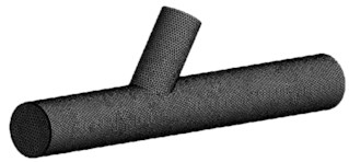
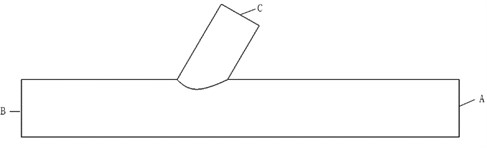
The tetrahedral structure was used to mesh the 3D model, and the schematic diagram of the cross-sectional structure and the mesh structure are shown in Fig. 1.
Fig. 1Flow channel meshing and cross-sectional structure
3.1. Numerical analysis of different inlet pressures on tee hole machining
As shown in Fig. 1, A is selected as the pressure inlet, B and C as the pressure outlet, the volume fraction of the abrasive is set at 30 %, and the abrasive grain size is 400 mesh. The inlet pressure = 3, 4 and 5 MPa were used to analyse the distribution of the different parameters in the flow channel.
3.1.1. Numerical analysis of the dynamic pressure at different inlet pressures
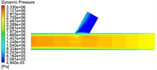
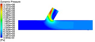
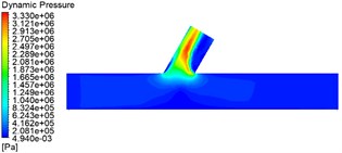
To obtain the dynamic pressure variation inside the flow channel. The planes over the two axes of the flow channel were selected for slicing the flow channel to get the dynamic pressure contour, as shown in Fig. 2.
Fig. 2 shows that as the inlet pressure gradually increases, the dynamic pressure in the straight pipe area gradually increases and becomes smaller at the cross hole. This is because the abrasive enters the runner after a violent collision with the wall at the entrance. The clash with the wall gradually decreases, with the most violent collision at the cross hole. Hence, it gradually becomes more negligible to a minimum value. As the inlet pressure increases from 3 MPa to 5 MPa, the dynamic pressure at the cross-hole becomes progressively higher, and the difference between the 4 MPa and 5 MPa values is insignificant.
Fig. 2Dynamic pressure contour for different pressure
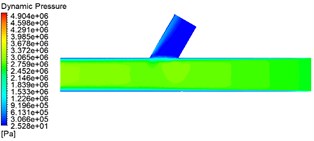
a) 3 MPa
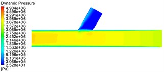
b) 4 MPa
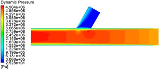
c) 5 MPa
3.1.2. Numerical analysis of wall shear forces at different inlet pressures
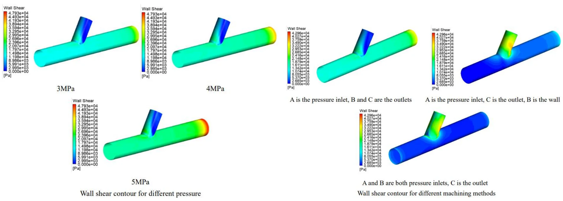
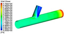
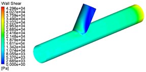
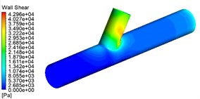
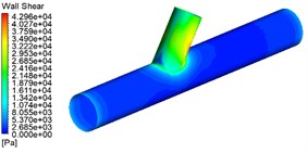
Wall shear is an essential factor in illustrating the effect of machining, and a wall shear contour is obtained as shown in Fig. 3.
As can be seen from Fig. 3: (1) The wall shear in the straight tube area becomes progressively higher at different pressures because this is because the increase in inlet pressure allows the abrasive to gain more energy and the abrasive particles to be better finished, which is shown in the contour diagram as an increase in wall shear. (2) different pressure cross-hole area wall shear growth is not enormous, from the dynamic pressure and wall shear can be obtained when the choice of 4 MPa is reasonable.
Fig. 3Wall shear contour for different pressure
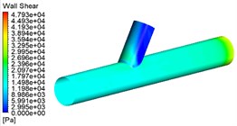
a) 3 MPa
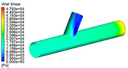
b) 4 MPa
c) 5 MPa
3.2. Numerical analysis of the machining of tee holes by different machining methods
The inlet pressure was set at 3 MPa, and the volume fraction of the abrasive was 30 %, with a grain size of 400 mesh. The different machining methods show the dynamic pressure distribution and wall shear distribution in Fig. 4 and Fig. 5.
From Fig. 4, Fig. 5 can be found A for the pressure inlet C for outlet B for the closed wall than A for the pressure inlet, B, C for the outlet straight tube area dynamic pressure is small, wall shear force is large. A, B at the same time for the pressure inlet C for the outlet than A for the pressure inlet C for the outlet B for the closed wall straight pipe area dynamic pressure, wall shear force is large. Furthermore, the three processing methods in the cross-hole area of the cross-hole boundary and the cross-hole wall processing effect are best. The choice of A, and B for the pressure inlet at the same time, for the processing method of double inlet processing, is conducive to workpiece processing.
Fig. 4Dynamic pressure contour for different machining methods
a) A is the pressure inlet, B and C are the outlets
b) A is the pressure inlet, C is the outlet, B is the wall
c) A and B are both pressure inlets, C is the outlet
Fig. 5Wall shear contour for different machining methods
a) A is the pressure inlet, B and C are the outlets
b) A is the pressure inlet, C is the outlet, B is the wall
c) A and B are both pressure inlets, C is the outlet
4. Conclusions
1) The solid-liquid two-phase flow model of a tee tube processed by abrasive flow was established, and numerical simulations of abrasive flow under different conditions were carried out to obtain the influence of inlet pressure and processing method on the dynamic pressure and wall shear force inside the tube.
2) Inlet pressure is the main reason for the influence of fluid pressure at the wall. For this article, 4 MPa after increasing the pressure processing effect is not apparent. To prevent excessive pressure on the parts by the damage, the actual processing selected 4 MPa as the processing pressure.
3) The dual-entry machining method, in which A and B are both pressure inlets, is the preferred machining method.
References
-
G. Hang, P. Can, and W. Xuanping, “Research progress on surface finishing technology of aeronautical complex structural parts manufactured by additive manufacturing,” Aeronautical Manufacturing Technology, Vol. 62, No. 9, pp. 14–22, 2019.
-
L. Yanbiao, C. Qiang, and Z. Li, “Titanium alloy thin-walled curved surface liquid metal-abrasive flow machining simulation and experimental research,” Journal of Mechanical Engineering, Vol. 57, No. 23, pp. 220–231, 2021.
-
S. Dhull, R. S. Walia, Q. Murtaza, and M. S. Niranjan, “Experimental, computational and mathematical analysis of hybrid abrasive flow machining process,” International Journal of Precision Engineering and Manufacturing, Vol. 22, No. 10, pp. 1657–1680, Oct. 2021, https://doi.org/10.1007/s12541-021-00565-3
-
Y. Fu, H. Gao, Q. Yan, X. Wang, and X. Wang, “Rheological characterisation of abrasive media and finishing behaviours in abrasive flow machining,” The International Journal of Advanced Manufacturing Technology, Vol. 107, No. 7-8, pp. 3569–3580, Apr. 2020, https://doi.org/10.1007/s00170-020-05288-9
-
W. Haiquan, F. Yuanzheng, G. Hang, and W. Xuanping, “Study on prediction of surface roughness for abrasive flow machining,” Journal of Mechanical Engineering, 2022.
-
L. Xiao, Y. Hongchao, and M. Lin, “Numerical simulation study on the processing of abrasive flows in slender pipes based on the Euler-Euler method,” Journal of Dalian University of Technology, Vol. 61, No. 2, pp. 143–150, 2021.
-
Cheng K. et al., “Development of the improved Preston equation for abrasive flow machining of aerofoil structures and components,” Proceedings of the Institution of Mechanical Engineers, Part J: Journal of Engineering Tribology, Vol. 233, No. 9, pp. 1397–1404, 2019.
-
S. Mohseni-Mofidi, L. Pastewka, M. Teschner, and C. Bierwisch, “Magnetic-assisted soft abrasive flow machining studied with smoothed particle hydrodynamics,” Applied Mathematical Modelling, Vol. 101, pp. 38–54, Jan. 2022, https://doi.org/10.1016/j.apm.2021.07.015
-
L. Junye, Z. Zhibao, Z. Xinming, S. Guangfeng, Z. Weihong, and S. Ningning, “Quality analysis for abrasive flow precision machining of special-shaped holes,” China Mechanical Engineering, Vol. 32, No. 17, pp. 2063–2073, 2021.
-
J. Li et al., “Vortex formation mechanism and experimental research of abrasive flow precision machining special inner curved surface based on large eddy simulation,” The International Journal of Advanced Manufacturing Technology, Vol. 116, No. 5-6, pp. 1633–1651, Sep. 2021, https://doi.org/10.1007/s00170-021-07537-x
-
Chengyu Xu et al., “Large eddy simulation studies of two-phase flow characteristics in the abrasive flow machining of complex flow ways with a cross-section of cycloidallobes,” Journal of Hydromechatronics, Vol. 5, No. 2, pp. 136–166, 2022.
-
H. Si, Jiaxing Huang, Zhiquan Hui, Maodong Li, and W. Ye, “Wear calculation of sandblasting machine based on EDEM-FLUENT coupling,” International Journal of Hydromechatronics, Vol. 1, No. 4, pp. 447–459, 2018.
About this article

The authors would like to thank the Science and technology development plan project of Jilin province No. 20220201036GX and 20210201057GX.
The datasets generated during and/or analyzed during the current study are available from the corresponding author on reasonable request.
The authors declare that they have no conflict of interest.
