Abstract
The stiffness is the main reason that restricts the large-scale of composite ships, the basis to solve this problem is to solve the stiffness of composite ships’ skeleton structure. Based on classical laminates theory, this paper calculated the equivalent in-plane stiffness and bending stiffness of composite hat stiffened laminate using equivalent stiffness principle. The hat stiffened laminate can be simplified and equivalent to orthotropic laminates using this solution idea, which solves the problem that it is difficult to obtain the analytical solutions of deformation, stress and strain of stiffened laminate. The research results can be used to calculate the stiffness of composite stiffened laminate and the local or global stiffness of the hull girder with such a skeleton structure.
1. Introduction
The single-shell skeleton structure is a typical form of composite hull, which is composed of composite panels and stiffeners. The stiffener is used to strengthen the stiffness and strength of the panels. Common stiffeners include L-shaped, T-shaped, hat shaped, etc. [1]. Although the hap stiffener is complex in technology, its strength and stiffness performance are more excellent, which is a hot research topic in composite field. For example, Yetman et al. [2-3] have studied the debonding behavior between the hat stiffener and the panel, Mo and Ge [4] have conducted experimental research and structural optimization design on the failure of the hat stiffened plate under axial load, Wan et al. [5] have studied on the buckling and post-buckling behavior of hat-stiffened composite panels under axial compressive load.
However, there are few reports on the stiffness of hat stiffened composite laminate. Hu et al. [6] have carried out research on tensile and bending stiffness of hat stiffened laminated beams, but it is only applicable to beam structures and cannot be extended to plate frame structures. This is because it is very difficult to calculate this structure’s stiffness using the classical laminated plate theory [7], and the approximate calculation can only be carried out by combining the equivalent stiffness method. For example, Zhou et al. [8] use the equivalent stiffness method to study the dynamic effects of composite sandwich plates with honeycomb structures, and Sun et al. [9] use the equivalent elastic model to study the elastic properties and lateral stiffness of multi-ribbed walls, and Wang et al. [10] used this method to study the buckling behavior of composite stiffened box structures. These studies all show that the equivalent stiffness is a good method to develop complex composite structures. Qiu and Li [11] calculated the equivalent stiffness of typical elements of composite hat stiffened laminate based on the classical laminated plate theory and the equivalent stiffness method, Wu et al. [12] verified accuracy of this method by experiment and simulation. On this basis, this paper further calculated the equivalent in-plane stiffness and bending stiffness of the entire hat stiffened laminated plate structure.
2. Solution idea of equivalent stiffness on composite hat stiffened laminate
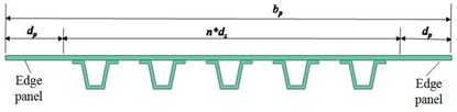
In Fig. 1, the composite hat stiffened laminate with a length of , a width of , an -axis along the stiffener direction, and a -axis perpendicular to the stiffener direction. The cross-section dimension is shown in Fig. 2, the spacing of stiffeners is , the width of plate edge is , and the stiffeners’ number is . In the following formula, subscript represents stiffened laminated element, and represents edge panel.
The stiffness is a kind of ability to resist external loads. There is a linear relationship between deformation and load when the structure is stressed within the elastic range, as long as the deformation coordination between its constituent elements is maintained, the forces acting on it can be superimposed. The solution idea of this paper is that divide the hat stiffened laminate into stiffened plate elements and 2 edge plates, as shown in Fig. 1, calculate their stiffness respectively, and then obtain the stiffness of the stiffened laminate by superposition. The stiffness of the hat stiffened laminated element has been solved in reference [11].
Fig. 1Schematic of composite stiffened laminate
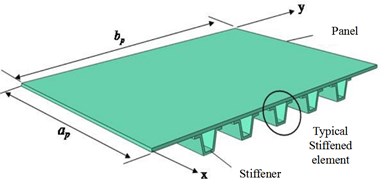
Fig. 2Section schematic of composite laminate with hat stiffeners
3. Calculation of equivalent in-plane stiffness of hat stiffened laminate
In the following formulas, the meaning and calculation formula of , , and can refer to reference [11].
3.1. Longitudinal in-plane stiffness
The longitudinal in-plane stiffness of stiffened laminate is equal to the sum of the longitudinal in-plane stiffness of typical stiffened elements and 2 edge panels, namely:
3.2. Transverse in-plane stiffness
When calculating the transverse in-plane stiffness of stiffened laminate, which is decomposed into segments with typical stiffened elements in the middle and 2 edge panels on both sides. When bearing the axial force per unit length, the longitudinal deformation of the stiffened laminate is the sum of the deformation of each segment, namely:
where, is the transverse in-plane stiffness of the stiffened laminate along the x direction per unit length, is the width of each segment, and is the transverse in-plane stiffness of each segment. The transverse in-plane stiffness of the edge panels is calculated as follows:
Then the transverse in-plane stiffness of the stiffened laminate:
3.3. In-plane Poisson's ratio
When bearing axial force , the strain of the stiffened laminate along the x direction is , and the strain along the y direction is , then the in-plane Poisson’s ratio is defined as . The deformation of stiffened laminated plate along the direction is the sum of deformation of each segment, namely:
where, is the in-plane Poisson’s ratio of each segment, is the width of each segment. The calculation formula of edge panels is as follows:
Then the in-plane Poisson’s ratio of stiffened laminate:
3.4. In-plane shear stiffness
Assume that the stiffened laminate bears the shear force along the direction, the shear strain of the stiffened laminate is , the shear force of each segment is ,and the shear strain of each segment is , in order to maintain deformation coordination, the shear strain of each segment should be the same as that of the stiffened laminate, namely:
where, is the in-plane shear stiffness of stiffened laminate, and is the in-plane shear stiffness of each segment.
In addition, , the stiffness of stiffened laminate can be obtained:
4. Calculation of equivalent bending stiffness of composite stiffened laminate
In the following formulas, the meaning and calculation formula of , , and can refer to reference [11].
4.1. Longitudinal bending stiffness
The longitudinal bending stiffness of stiffened laminate is equal to the sum of that of n stiffened elements and 2 the edge panels, namely:
4.2. Transverse bending stiffness
When calculating the transverse bending stiffness of stiffened laminate, which is decomposed into segments. Under the bending moment, the corners at both ends of the stiffened laminate should be the sum of the corners of each segment in direction, namely:
where, is the transverse bending stiffness per unit width of the stiffened laminate along the direction, and is the transverse bending stiffness per unit width of each segment along the direction. The calculation formula of the transverse in-plane stiffness of the edge panels is as follows:
Then the transverse bending stiffness of the stiffened laminate:
4.3. Bending Poisson’s ratio
When bearing axial force , assume that the curvature of the bending deformation of stiffened laminate in the direction is . The curvature of bending deformation in direction is . Then the bending Poisson’s ratio of stiffened laminate is defined as . The bending angle at both ends of the stiffened laminate along the direction is the sum of the angles of each segment, namely:
where, is the bending Poisson’s ratio of each segment and is the width of each segment. The bending Poisson’s ratio formula of the edge panels is as follows:
Then the bending Poisson’s ratio of stiffened laminate:
4.4. Torsional stiffness
When bearing torque , the torsion ratio of stiffened laminate is , the torque of each segment is , and the torsion ratio is . The torque of the stiffened laminate is the sum of the torque of each segment, and the torque ratio is equal to that of each segment, namely:
Simplify the above formula to obtain the torsional stiffness of stiffened laminate:
5. Calculation of equivalent stiffness coefficient
After the calculation of equivalent stiffness, composite stiffened laminate can be equivalent to orthotropic composite laminate. The stiffness coefficient can be calculated according to the relationship between the mid-plane strain, curvature, internal force and internal moment of the composite laminate.
5.1. Calculation of in-plane stiffness coefficient
The relationship between in-plane strain and in-plane internal force of orthotropic composite laminate:
where, is the in-plane strain of the laminate, is the in-plane internal force, is the in-plane flexibility coefficient.
When the composite stiffened laminate bears in-plane internal force , the following formula can be obtained according to the Eq. (19):
Simplify the above equation to obtain:
In the same way, we can get:
In-plane stiffness matrix of composite stiffened laminate is the transpose of in-plane flexibility matrix.
5.2. Calculation of bending stiffness coefficient
The relationship between curvature and internal moment of orthotropic laminate:
where, is the curvature of the composite laminate, is the internal moment, is the bending flexibility coefficient.
In the same way as section 5.1, we can get:
Bending stiffness matrix of composite stiffened laminate is the transpose of bending flexibility matrix.
6. Conclusions
The research on the stiffness characteristics of composite stiffened laminate is the basis of that of composite hull. Based on the classical laminated plate theory, the equivalent in-plane stiffness and bending stiffness of composite hat stiffened laminate are obtained using the stiffness equivalence method.
Using the solution idea in this paper, the arbitrary composite stiffened laminate can be transformed into orthotropic laminate. Under the condition of the specific boundary conditions and loads, the deformation, internal force and bending moment of orthotropic laminated plates can be solved first, and then the deformation, stress and strain of each element of stiffened laminate can be further solved according to the classical laminated plate theory. The equivalent stiffness of stiffened laminate calculated by this method refers to the average distributed stiffness. Therefore, the more intensive the number of stiffeners is, the more accurate the calculation results will be.
The research results in this paper can be used to calculate the stiffness of composite stiffened laminate, and the local or global stiffness of the hull girder with such a skeleton structure.
References
-
M. F. Cao and L. Yang, “Application of composite materials in ship design and construction,” Naval Architecture and Ocean Engineering, Vol. 2, pp. 38–43, 2006, https://doi.org/10.3969/j.issn.1005-9962.2006.02.014
-
J. E. Yetman and A. J. Sobey, “Investigation into skin stiffener debonding of top-hat stiffened composite structures,” Composite structure, Vol. 132, pp. 1168–1181, 2015, https://doi.org/10.1016/j.compstruct.2015.06
-
J. E. Yetman, A. J. Sobey, J. I. R. Blake, and R. A. Shenoi, “Modelling the variability of skin stiffener debonding in post-cured top-hat stiffened panels,” Composite Structures, Vol. 211, pp. 187–195, Mar. 2019, https://doi.org/10.1016/j.compstruct.2018.11.078
-
Y. Mo, D. Ge, and B. He, “Experiment and optimization of the hat-stringer-stiffened composite panels under axial compression,” Composites Part B: Engineering, Vol. 84, pp. 285–293, Jan. 2016, https://doi.org/10.1016/j.compositesb.2015.08.039
-
H. L. Wan, W. M. Gong, and J. E. Qin, “Research on the buckling and post-buckling behavior of hat-stiffened composite panels under axial compressive load,” Structure and Environment Engineering, Vol. 46, No. 1, pp. 31–34, 2019, https://doi.org/10.19447/j.cnki.11-1773/v.2019.01.005
-
M. Y. Hu, B. Zheng, and A. W. Wang, “Theoretical calculation of stiffness of laminated composite beam with hat-section,” Journal of Naval University of Engineering, Vol. 29, No. 6, pp. 6–12, 2017, https://doi.org/10.7495/j.issn.1009-3486.2017.06.002
-
G. Q. Jiao and P. R. Jia, Mechanics of Composite Materials. Xi’an: Northwest Polytechnical University Press, 2008.
-
X. Q. Zhou, L. Wang, D. Y. Yu, and C. Y. Zhang, “Dynamic effective equivalent stiffness analysis on the periodical honeycomb reinforced composite laminated structure filled with viscoelastic damping material,” Composite Structures, Vol. 193, pp. 306–320, Jun. 2018, https://doi.org/10.1016/j.compstruct.2018.03.066
-
J. Sun, Y. Jia, and Y. L. Mo, “Evaluation of elastic properties and lateral stiffness of multi-ribbed walls based on equivalent elastic model,” Engineering Structures, Vol. 72, pp. 92–101, Aug. 2014, https://doi.org/10.1016/j.engstruct.2014.04.014
-
P. Wang, X. Huang, Z. Wang, X. Geng, and Y. Wang, “Buckling and post-buckling behaviors of a variable stiffness composite laminated wing box structure,” Applied Composite Materials, Vol. 25, No. 2, pp. 449–467, Apr. 2018, https://doi.org/10.1007/s10443-017-9643-3
-
J. B. Qiu and H. D. Li, “Equivalent stiffness calculation of typical plate element of composite cap stiffened laminates,” Composites Science and Engineering, Vol. 7, pp. 33–39, 2020, https://doi.org/10.3969/j.issn.1003-0999.2020.07.005
-
J. Wu et al., “Equivalent bending stiffness of composite hat-stiffened panel,” Acta Materiae Compositae Sinica, Vol. 29, No. 12, pp. 1–8, 2022, https://doi.org/10.13801/j.cnki.fhclxb.20211208.001
Cited by
About this article

The project is supported by Youth Program of National Natural Science Foundation of China: 51609252.
The datasets generated during and/or analyzed during the current study are available from the corresponding author on reasonable request.
The authors declare that they have no conflict of interest.
