Abstract
Damping is focused in a mass of engineering applications at present. In this paper a new laminate element rests on the higher-order zig-zag theory for composite plates were presented. And then, viscoelasticity damping and frictional damping models in delaminated composites were established. The damping changes of delaminated composites with different boundary conditions were investigated via the laminate element, the effects of area and location on damping were also researched. The results revealed that viscoelasticity damping and frictional damping are in the same order of magnitude even delamination area is small, and frictional damping increase significantly when delamination area enlarged, frictional damping is needed to be considered in the damping research of delaminated composites.
1. Introduction
Composite materials has widely used during the last decades. We could find the application of composite materials from the aviation industry to sports equipment. Since their first appearance and application, most researchers have focused on static characteristics and anisotropy properties, an extensive literature is available in this filed. Beside stiffness and strength, their dynamic responses, e.g. vibration and damping, also need deep understanding in engineering design for purpose of vibration and noise controlling.
The damping of the structure is possibly caused by the resistance of external, e.g. air drag and support friction. It also possibly comes from the interior energy dissipation of structure, including the viscidity of material, friction of interior contact surfaces, heat and sound production and damage evolution [1, 2]. Polymer matrix composites are generally recognized possessing better damping capacity, several orders of magnitude higher, than traditional metal materials because of their visco-elastic matrix. Additionally, various defects often found in composites can dissipate energy during cyclic load and elevate damping furthermore [3-5].
For the widely used laminate composite, defects include matrix cracks, delamination, imperfect fiber/matrix bounding and fiber breakage and these defects are considered inevitable during manufacture and service [6]. For fiber composites, Friction of crack surfaces and damage development consume energy. For instance, Cho C. [7] presented an estimation of interfacial friction in fiber-reinforced ceramics via increasing temperature during cyclic loading. David B. [8] used an indentation method to obtain the fiber/matrix interfacial frictional sliding stress and debone energy of a SiC/glass-ceramic composite. One of the macro phenomena of these energy dissipations manifests of damping under cycle loads. Birman V. [9, 10] analytically modeled the relation between damping and micro matrix crack of ceramic matrix unidirectional and cross-ply composites. Damping is also used to figure out damage level of structure. Relations between damping and damage have been extensively studied theoretically and experimentally. Damping is found sensitive to damage, thus it is recommended as an effective representation of damage evaluation [11-16].
Among damages, delamination is most concerned for composite laminate because of it might lead fatal consequence without obviously visual mark. The gradients of in-plane displacements along thickness are discontinuous in delaminated interface. Various approaches have been proposed to represent this discontinuity. For example, Jim K. S. build a novel transition element based on first-order theory [17], Cheng Z. Q .established a spring-layer model to simulate vibration of multilayered laminate with weak interface [18], Marco D. S. develop a nonlinear theory of multilayered composites with interface slips based on higher-order shear model [19], and a higher-order zig-zag theory established by Cho M was employed for the natural frequency analysis of delaminated plates [20]. To adapt the complicated configurations of structure and irregular shaped multi plies delamination, FEM algorithms have been developed based on the various laminate plate theories which consider the inter-laminar displacement discontinuity introduced by delamination [20, 25]. Among them, FEM models founded on layer-wise plate theory [21] and higher-order zig-zag theory [20] exhibit satisfying accuracy. However, the former defines degree of freedom (DOF) upon each individual ply, thus it is not computationally efficient. Whereas, the latter theory only need additional DOF when delamination occurs. In this study, a new four-node plane element was developed to represent damping of delaminated plates based on the higher-order zig-zag theory.
2. Higher-order zig-zag theory of delaminated composites
2.1. Displacement model
An abridged general view of composite plates with multi-delaminations is shown in Fig. 1. The discontinued displacement field predicted by higher-order zig-zag theory [20] includes Heaviside functions to adapt the displacement discontinuity between the delaminated laminas. Meanwhile, the transverse shear stresses of this theory are continuous through the thickness and vanish on the top and bottom surface as well as on the interior surfaces of delamination.
The discontinued displacement field for a plate composite with multi-delaminations can be written as follows [20]:
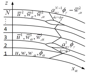
The subscript denotes the two in plane directions of and , as illustrated in Fig. 1. the first term in right side of Eq. (1) is the in-plane displacement on the reference plane, the three terms following are those of linear, square and cubic terms along thickness, the forth term characterize slope variation between neighbor plies caused by stiffness jump and delamination, the last term represent the relative shear displacement on the interfacial crack surfaces. are the rotations in the normal direction of the reference plane about the coordinate, and are the square and cubic displacement coefficients respectively. The first and second terms in right side of Eq. (2) are deflection on the reference plane and opening of delamination. is the number of ply, the terms and represent possible jumps in the slipping and opening displacements, means the distance between the kth interlaminar to the bottom reference plane, is the Heaviside function. The deformed schematic configuration is shown in Fig. 2.
In the well bonded interface composites plate, transverse shear stress and displacement should be continuous, in the delaminated interface, transverse stress vanished but it is still continuous. Applied the shear stress continuity conditions of the interface, the slope change could be written as:
The details of coefficients meaning can be found in reference [20].
Fig. 1A composite laminate with multiple delamination
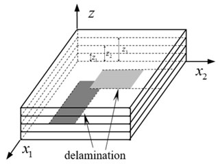
Fig. 2Schematic deformations of multiply delaminated composite
2.2. Constitutive equations
From Eq. (1) and Eq. (2), in-plane and transverse strains are derived as:
The constitutions an individual ply in the global coordinate system are expressed as:
where denotes the transformed stiffness of the th lamina. Through integrating stiffness of each ply, the resultant constitutive relations for the laminate are obtained, as shown in matrix form below:
The formula derivation and variable specific meaning in Eq. (7) and Eq. (8) could be found in reference [20].
3. Finite element algorithm
A four-node plane element is developed on the foundation of the proposed theory. The primary displacement of the plate is interpolated in terms of nodal displacements via shape functions, as below:
where is the node number in a plate unit, denotes a Lagrange shape function and , , are Hermite interpolation functions.
Strains relate to nodal displacement in expression as:
where is the in-plane geometry matrix, denotes the transverse shear geometry matrix, these two items are deviated from shape function, and are node displacements
The DOF of each node on the element will increase with number of delamination, it is expressed as . In the other word, DOF is 7 for an un-delaminated plate and it increases 5 for each delamination. Correspondingly, sub matric of and are partitioned to two blocks:
The first block (and ) relates to un-delamination DOF, while the second block (and ) to delamination one. The detailed description of and can be found in the appendix.
4. Damping model of delaminated plates
Damping properties of a structure can be characterized by specific damping capacity (SDC) [26-28]. SDC, denoted , is expressed by the following formula:
where and denote the dissipated energy and largest strain energy in one load cycle, respectively.
If interior delamination surfaces of a composite laminate contact and have relative slide, the frictional energy dissipation also contribute to damping. Together with damping caused by materials viscoelasticity, SDC of delaminated plates can be rewritten as:
where is viscoelastic damping dissipated energy, is frictional damping dissipated energy, and denote viscoelastic specific damping capacity (VSDC) and frictional specific damping capacity (FSDC), respectively. Note that, other damping resources such as damage evolution are not taken account here.
4.1. Viscoelastic damping model of delaminated plates
and can be expressed as a summation of energies corresponding to six strain components. SDC corresponding to each strain component, named as , can be obtained through unidirectional damping experiment or FEM analysis [29].
For a linear elastic material, the deformation energy stored in an element is:
where is the energy component.
The corresponding viscoelastic damping energy dissipation of the element can be written in terms of the specific damping capacity along each direction as:
Therefore, SDC of laminate composite can be expressed as:
For a plate model, the off-plane normal strain is neglected, therefore, strain energy has three in-plane components and two transverse shear components.
In the higher-order zig-zag theory, in-plane strain and transverse strain are all higher order function of coordinates and contains a step-function at the interface of the lamina. It is difficult to calculate strain energy and viscoelastic damping via integration layer by layer directly. Here, numerical integration is adopted, and the strain energy corresponding to one strain component, named as , is accumulated as:
where, and is the ply number, is the integrate point number of each ply, is the thickness of each ply, is the plate element area, and denote the stress and strain at th integrate point locating th ply, respectively.
4.2. Frictional damping model of delaminated plates
Normal stress is usually neglected in the thin plate theory for it is much smaller than the in-plane normal stress. However, it is essential for calculating frictional energy dissipation introduced by delaminated interface. Here, between plies is estimated through force equilibrium condition in thickness. As illustrated in Fig. 3, the inter-ply normal stress between th ply and th ply, named as , is determined by following equation:
where, and denote the shear stress increments on the two lateral sides face of th ply, is the thickness of th ply, and are the element length of the and directions, is the transverse external resultant force applied (below above) the th ply and it is postulated going through the central point of the element.
To delaminated interface will be null when interface is open. So, the contact pressure on the delamination surface is expressed with one-side condition as:
The symbol of ‘〈 〉’ means it takes the value of variable inside if the variable is positive otherwise it equals zero. The contact force is further supposed to be evenly distributed for simplification. If the structure is supposed experience periodic load, the compressive stress on crack surface also alternates with the same frequency.
If the shear stress on delaminated (but compressed) surface has overcome the static frictional resistance, the two delamination surfaces will have relative shear displacement and frictional force does work. The frictional force is the product of compression and slide friction coefficient . In order to correspond to the relative displacement, the transverse shear stress on the stratified plane is also divided into two directions of -axis and -axis. Therefore, sliding friction conditions of direction and direction can be written as:
When relative displacement occurs on delamination surface, the friction energy dissipation of a delamination in one load cycle can be expressed as:
where, is the peak magnitude of average contact pressure, and denote the shear relative displacement of the upper and lower surfaces of the th delamination in one element. is the delamination area of one element, when delamination occurred in an element, delamination area equals the element area , otherwise equals 0. It is worth noting that, without consideration of the interaction between the contacted surfaces, , and may have a little difference comparing with the real situation.
The frictional energy dissipation of a composite plate can be obtained by summarized frictional energy dissipation of all elements.
5. Numerical examples
In order to validate the application of theoretical model developed above in structure, a plate finite element based this theory was implemented on platform of ABAQUS. The effects of the delamination area, delamination location and boundary conditions on the viscoelastic damping and friction damping of laminated plates are studied.
The material parameters of the fiber and the matrix of the laminated plates used in this paper are derived from the reference [29]. When the fiber volume fraction of this composite takes 60 %, the engineering constants and the SDC of single ply are calculated by mixture theory and employed from reference [29] respectively, as presented in Table 1 and Table 2.
Damping properties of the single layer plate are show in Table 2.
Table 1Engineering constants of single layer plate
/ GPa | / GPa | / GPa | / GPa | ||
136.28 | 7.83 | 2.84 | 1.5 | 0.28 | 0.35 |
Table 2Damping properties of single layer
0.00123 | 0.01256 | 0.01688 | 0.02164 | 0.02164 | 0.00123 |
Fig. 3FE model and ply sequences
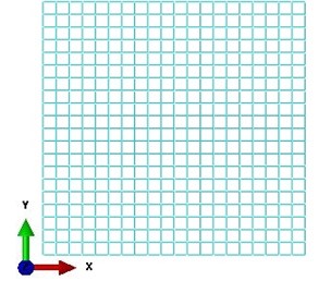
a) FEM element mesh
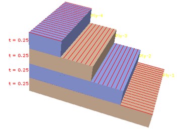
b) Ply sequences
A fictitious square composite laminate with dimension of 100 mm×100 mm×1 mm was used as example. Its stacking sequences are [0°, 90°, 90°, 0°] and each ply layer is 0.25 mm in thickness. 400 uniform square elements were discretized for the FE model and each element involves 4 plies, as demonstrated in Fig. 3. Three boundary conditions were considered here, i.e. (1) One side was clamped ( 0 mm) and the other three sides were free; (2) One side was clamped ( 0 mm) and the other three sides were free; (3) All the four sides are clamped. Symmetrical cycle sinusoid uniform pressure (or traction) 0.004 MPa is applied on upper surface of the plate. Note that, during half of one load cycle the upper surface is in traction and delaminated surfaces separate and thus no frictional dissipation takes place.
5.1. Delamination area influence on special damping capacity
A serious square shape delaminations were preset between ply 2 and ply 3 ( 0.5 mm) in the laminated plate. Their areas are 10 mm×10 mm, 20 mm×20 mm, 30 mm×30 mm, 40 mm×40 mm, 50 mm×50 mm, 60 mm×60 mm, 70 mm×70 mm and 80 mm×80 mm respectively and all of them locate in the middle region of the plate. Fig. 4 shows the relationship between the viscoelastic damping capacity (VSDC), friction damping capacity (FSDC) and the delamination area under the three boundary conditions.
Fig. 4Delamination area influence on SDC
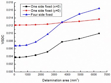
a) VSDC
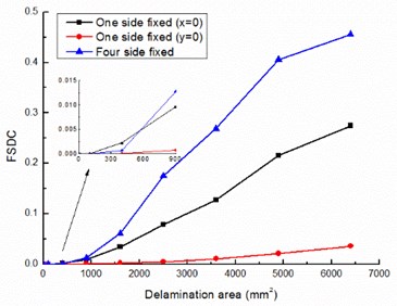
b) FSDC
As see from the Fig. 4, VSDC and FSDC both increase with the increase of the delamination area under the three kinds of boundary conditions, and the damping capacity with four edges clamped boundary condition grows quicker than that with two kinds of one side clamped boundary condition when delamination area increases. In the boundary conditions (1) and (3), FSDC and VSDC are numerically equal with each other when the delamination area is up to 30 mm×30 mm (less than 10 % of the total area), is greater than when the delamination area enlarge continually, and is two orders of magnitude more than when delamination area reaches 64 % of the laminated plate. In the boundary condition (2), FSDC and VSDC are numerically close to each other when the delamination area is up to 40 mm×40 mm (about 16 % of the total area), and increases more significant than when the delamination area expand continually. Compared with the three lines of differ boundary conditions in Fig. 4(a) and Fig. 4(b), we can also know that boundary conditions significant influences VSDC and FSDC.
5.2. Delamination location influence on special damping capacity
In order to study the influence of the delamination position on damping of the composite laminated plate, the laminated plate models with different delamination positions are established respectively. All delamination areas are 40 mm×40 mm and occur between layer 2 and layer 3. In boundary condition (1) and (3), the distances to one side ( 0 mm) are 30 mm, 40 mm, 50 mm and 60 mm and 70 mm in turn, and they keep at middle of the plate in -axis direction. In boundary condition (2), the delamination location changes similar to boundary condition (1) but in -axis direction. As show in Fig. 5, in boundary condition (1) and (3), both VSDC and FSDC with four edges clamped boundary condition are higher than those with one side clamped boundary condition and is one order of magnitude more than . In boundary condition (1) and (2), both VSDC and FSDC small decrease with the delamination location away from the fixed boundary. In boundary condition (2), VSDC is closed to FSDC during the delamination area is 16 % of total plate area. Considered the cycle load condition applied on the plate, during half of one load cycle the upper surface is in traction thus no frictional dissipation takes place, but viscoelastic dissipation appears in the whole load cycle, that is to say, in boundary condition (2), frictional dissipation is also considerable.
Fig. 5Delamination location influence on special damping capacity
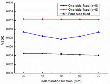
a) VSDC
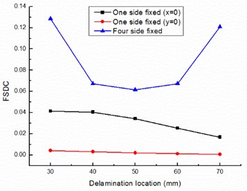
b) FSDC
Actually, may be smaller than the calculated value, because of this paper does not consider the friction influence when calculate the deformation. However, the friction energy dissipation on layer surface will be one of the main sources of damping without doubt when the delamination damage area is large enough.
6. Conclusions
In this paper, a four-node finite element was constructed based on higher-order shear deformation theory to calculate damping capacity of composite plates with delamination. The effects of area and location of delamination on viscoelasticity damping and frictional damping of a four layer laminate composite are researched. The results reveal that viscoelasticity damping and frictional damping will rise as delamination area increased in all cases and the friction energy dissipation will increase significantly, it shows the close relationship between the friction energy dissipation and the area of delamination. Friction damping will become one of the main sources of damping in laminates when the delamination area is large enough, it needed to be considered in engineering design.
References
-
Melo Jose Daniel D. Time and temperature dependence of the viscoelastic properties of CFRP by dynamic mechanical analysis. Composite Structures, Vol. 70, 2005, p. 240-253.
-
Kumar Rabindra Patel, Bishakh Bhattacharya, Sumit Basu A finite element based investigation on obtaining high material damping over a large frequency range in viscoelastic composites. Journal of Sound and Vibration, Vol. 303, 2007, p. 753-766.
-
Chandra R., Singh S. P., Gupta K. Damping studies in fiber-reinforced composites – a review. Composite Structures, Vol. 46, 1999, p. 41-51.
-
Zhang P. Q. Influence of some factors on the damping property of fiber-reinforced epoxy composites at low temperature. Cryogenics, Vol. 41, 2001, p. 245-251.
-
Kubat J., Rigdahl M., Welander M. Characterization of interfacial interactions in high density polyethylene filled with glass spheres using dynamic-mechanical analysis. Journal of Applied Polymer Science, Vol. 39, Issue 7, 1990, p. 527-1539.
-
Hassan N. M., Batrar R. C. Modeling damage in polymeric composites. Composites, Part B, Vol. 39, 2008, p. 66-82.
-
Cho Chongdu, Holmes John W., Barber James R. Estimation of interfacial shear in ceramic composites from frictional heating measurements. Journal of the American Ceramic Society, Vol. 74, Issue 11, 1991, p. 2802-2808.
-
Marshall D. B., Oliver W. C. Measurement of interfacial mechanical properties in fiber-reinforced ceramic composites. Journal of the American Ceramic Society, Vol. 70, Issue 8, 1987, p. 542-548.
-
Birman Victor, Byrd Larry W. Effect of matrix cracks on damping in unidirectional and cross-ply ceramic matrix composites. Journal of Composite Materials, Vol. 36, 2002, p. 1858-1878.
-
Birman Victor, Byrd Larry W. Damping in ceramic matrix composites with matrix cracks. International Journal of Solids and Structures, Vol. 40, 2003, p. 4239-4256.
-
Saravanos D. A., Hopkins D. A. Effects of delaminations on the damped dynamic characteristics of composite laminates: analysis and experiments. Journal of Sound and Vibration, Vol. 192, Issue 5, 1996, p. 977-993.
-
Echtermeyer A., Engh B., Buene L. Lifetime and Young’s modulus changes of glass/phenolic and glass/polyester composites under fatigue. Composites, Vol. 26, Issue 1, 1995, p. 10-16.
-
Balasubramaniam K., Alluri S., Nidumolu P., et al. Ultrasonic and vibration methods for the characterization of pultruded composites. Composites Engineering, Vol. 5, Issue 12, 1995, p. 1433-1451.
-
Kyriazoglou C., Le Page B. H., Guild F. J. Vibration damping for crack detection in composite laminates. Composites: Part A, Vol. 35, 2004, p. 945-953.
-
Zhang Z., Hartwig G. Relation of damping and fatigue damage of unidirectional fiber composites. International Journal of Fatigue, Vol. 24, 2002, p. 713-718.
-
Cho M., Parmerter R. Efficient higher order composite plate theory for general lamination configurations. AIAA Journal, Vol. 31, Issue 7, 1993, p. 1299-1306.
-
Kim J. S., Cho M. Post buckling of delaminated composites under compressive loads using global-local approach. AIAA Journal, Vol. 31, 1999, p. 774-777.
-
Cheng Z. Q., Jemah A. K., Williams F. W. Theory for multilayered anisotropic plates with weakened interfaces. Journal of Applied Mechanics, Vol. 63, 1996, p. 1019-1026.
-
Sciuva M. D. Geometrically nonlinear theory of multilayered plates with interlayer slips. AIAA Journal, Vol. 35, Issue 11, 1997, p. 1753-1759.
-
Cho M., Kim J. S. Higher order zig-zag theory of laminated composites with multiple delaminations. Journal of Applied Mechanics, Vol. 68, 2001, p. 869-877.
-
Lee J., Gurdal Z., Griffin O. Layer-wise approach for the bifurcation problem in laminated composites with delaminations. AIAA Journal, Vol. 31, Issue 31, 1993, p. 331-338.
-
Dimitris I., Nikos A., Dimitris S., et al. A damping mechanics model and a beam finite element for the free vibration of laminated composite strips under in-plane loading. Journal of Sound and Vibration, Vol. 330, 2011, p. 5660-5677.
-
Kenan Y., Koruk H. A new triangular composite shell element with damping capability. Composite Structures, Vol. 118, 2014, p. 322-327.
-
Wang Y., Daniel J. Finite element analysis and experimental study on dynamic properties of a composite beam with viscoelastic damping. Journal of Sound and Vibration, Vol. 332, 2013, p. 6177-6191.
-
Niyari A. Nonlinear finite element modelling investigation of flexural damping behaviour of triple core composite sandwich panels. Materials and Design, Vol. 46, 2013, p. 842-848.
-
Adams R. D., Fox M. A. O., Flood R. J. L., et al. The dynamic properties of unidirectional carbon and glass fibre reinforced plastics in torsion and flexure. Journal of Composite Materials, Vol. 3, Issue 4, 1969, p. 594-603.
-
Adams R. D., Bacon D. G. C. Measurement of the flexural damping capacity and dynamic Young’s modulus of metals and reinforced plastics. Journal of Physics D: Applied Physics, Vol. 6, Issue 1, 1973, p. 27-41.
-
Ni R. G., Adams R. D. The damping and dynamic moduli of symmetric laminated composite beams: theoretical and experimental results. Journal of Composite Materials, Vol. 18, Issue 2, 1984, p. 104-121.
-
Tsai J. L., Chi Y. K. Effect of fiber array on damping behaviors of fibre composites. Composites Part B: Engineering, Vol. 39, 2008, p. 1196-1204.
About this article

This work was supported by the National Natural Science Foundation of China (Grant No. 11272147, 10772078), Chinese Aviation Science Fund (2013ZF52074), Fund of State Key Laboratory of Mechanical Structural Mechanics and Control (0214G02), SKL Open Fund (IZD13001-1353, IZD150021556), Priority Academic Program Development of Jiangsu Higher Education Institutions.
