Abstract
Statistical Energy Analysis (SEA) has been used to compute velocity responses and Coupling Loss Factors (CLF) for two composite laminates joined in a 'L' junction configuration. Two case studies were carried on SEA. The effect of fibre orientation on SEA parameters was studied. The effects of internal damping were also determined. The computation of SEA parameters has been done using classical wave approach and Finite Element Method using Nastran/Patran. CLF determined using classical wave approach is independent of fibre orientation and internal damping factor. This study using FEM reveals that the SEA parameters vary in comparison with classical wave approach as fibre orientation and internal damping are also considered in the analysis. Also, by classical wave approach, the CLF varied linearly with the increase in frequency while there was some scatter in CLF determined by finite element method.
Highlights
- Determination of SEA parameters for a composite laminates using Analytical (Classical Wave Approach) and Numerical (Nastran) methods.
- The effect of fibre orientation on SEA parameters was studied. The effects of internal damping were also determined.
- Concluded that the numerical method was able to predict the SEA parameters more accurately compared to that of Analytical Method.
1. Introduction
The analysis of complex structure subjected to dynamic loads can be studied in two different ways. The low frequency region is dominated by resonance peak and solved by deterministic approach. In the high frequency region, modal overlaps are high and cannot be solved using deterministic approach. SEA developed in early 1960’s [1, 2] can be used to predict vibration response of the structures subjected to high frequencies. It has a wide range of applications from automobiles to aerospace structures. SEA divides the complex structure into coupled subsystems, where the exchange of energies takes place. As pioneered by Lyon, SEA deals with computation of exchange of energies between subsystems using statistical approach. The exchange of energies between coupled subsystems has been studied by Scharton and Lyon [3], Newland [4] and Lyon and Eichler [5]. The SEA parameters of any structural problem subjected to high-frequencies can be computed by analytical approach using classical wave method [1], numerical approach using finite element analysis [6], experimental approach using power injection method [7], and receptance approach using green function method [8]. The CLF can also be determined by transient statistical energy analysis [9], experimental statistical energy analysis [10] and other hybrid methods.
It is important to study the vibration levels and high frequency noise response in aerospace and marine structures which mainly consist of stiffened plates. Composite materials have a wide range of application from marine structures, aerospace to automobile industries. It is essential to design these structures not only for static and low frequency vibrations (dynamic) but also for high frequency vibrations. This is mainly because of material properties like low density, high specific strength and high specific modulus. Different forms of composites like laminar composite structures, sandwich structures and honeycomb sandwich structures are used in building various components of aerospace and marine structures. In case of laminate composite structure, layers of lamina will be stacked and cemented in a particular sequence such that fibre orientation can be varied in each layer to match the required laminate property.
In this study, the SEA parameters have been processed for a L- laminate. The results of the analysis from analytical approach and numerical approach have been plotted and compared. The effect of fibre orientation and internal damping on the CLF and velocity responses has been compared by both analytical and numerical methods.
2. Theory
SEA deals with dividing the complex structure into subsystems and the transfer of energies between the subsystems through coupling joints are studied. The transfer of energies between subsystems (Fig. 1) is determined by calculating the vibration energy levels in each subsystem, by establishing power balance equation.
The standard power balance equation for an SEA model is based on the following assumption:
1) The energy flow between two coupled subsystems is relative to the differentiation in the subsystem modal energies.
2) The power loss in the subsystem is only due to internal damping loss factor , and the subsystem vibrates with energy when an input power is given.
The standard power balance equation is given by:
where, – power injected in subsystem , – frequency averaged energy in subsystem , – structural damping loss factor, – indicates spatial averaging, and bar indicates frequency averaging.
The power balance equation is given by:
where the power transmitted between subsystem and is given by:
The power balance equation can for n sub systems is given by:
3. Procedure
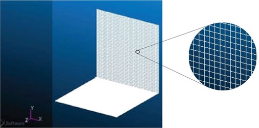
High frequency analysis was carried out on L-configuration composite laminate structure. Comparison of SEA parameters has been using classical wave approach and Finite Element approach using Nastran/Patran. The effects of fibre orientation and internal damping on SEA parameters were studied. The effect of fibre orientation on SEA parameters was studied by keeping the internal damping value as constant. Fibre orientation of 0°, 15°, 30°, 45° and 90° were considered for the analysis, while internal damping value was kept constant at 0.01. In addition, the effect of internal damping on SEA parameters was studied by keeping the fibre orientation constant. The value of internal damping was varied from 0.01 to 0.06 with an increment of 0.01 and the fibre orientation was considered at 15°. Two plates (Fig. 2) having same areas were used for the analysis. Coupling loss factors and velocity response in both the plates were computed. Material and physical properties are given in Table 1.
Fig. 1Flow of energy between two subsystems
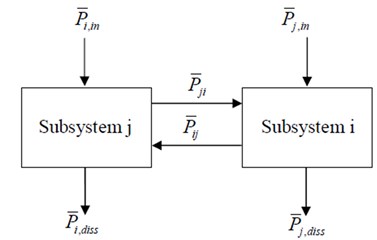
Fig. 2L-Plate
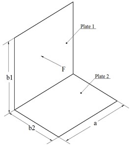
Table 1Material and physical properties of composite laminate
Material and physical properties | Plate 1 | Plate 2 |
Elasticity modulus of plies | 39 GPa, 8.6 GPa | 39 GPa, 8.6 GPa |
Poisson’s ratio of plies | 0.28, 0.0617 | 0.28, 0.0617 |
Density | 2.1 g/cm3 | 2.1 g/cm3 |
Material damping | 0.01, 0.02, 0.03, 0.04, 0.06 | 0.01, 0.02, 0.03, 0.04, 0.06 |
Number of plies | 4 | 4 |
Stacking sequence | [–, , , –] | [–, , , –] |
Orientation angles | 0°, 15°, 30°, 45°, 90° | 0°, 15°, 30°, 45°, 90° |
Plate size | 100 cm, 100 cm | 100 cm, 100 cm |
Total thickness | 0.4 cm | 0.4 cm |
3.1. Analytical formulation of composite laminate
SEA involves study of vibration response of complex structures subjected to transverse loads. SEA for composite laminate is applicable when modal overlap factor is high. Classical-wave approach for obtaining the coupling loss factor and input power of the composite laminates subjected to harmonic force are discussed. The coupling loss factor for a line coupled composite laminate is given by [11]:
where, is average modal frequency spacing, is the transmission co-efficient.
Average modal frequency spacing is given by:
where, is thickness of the laminate and is the surface area of the laminate, and are the longitudinal wave speed on and directions respectively.
Longitudinal wave speed for composite laminate is given by:
where, and are Elastic modulus in and directions respectively, is the density of the orthotropic material considered, and and are the poissions ratio.
Bending wave speed for composite laminate is given by:
Transmission co-efficient for composite laminate is given by:
where is the force impedance in -direction and is the number of subsystems connected at a common joint.
Force impedance is given by:
3.2. Numerical analysis for composite laminate
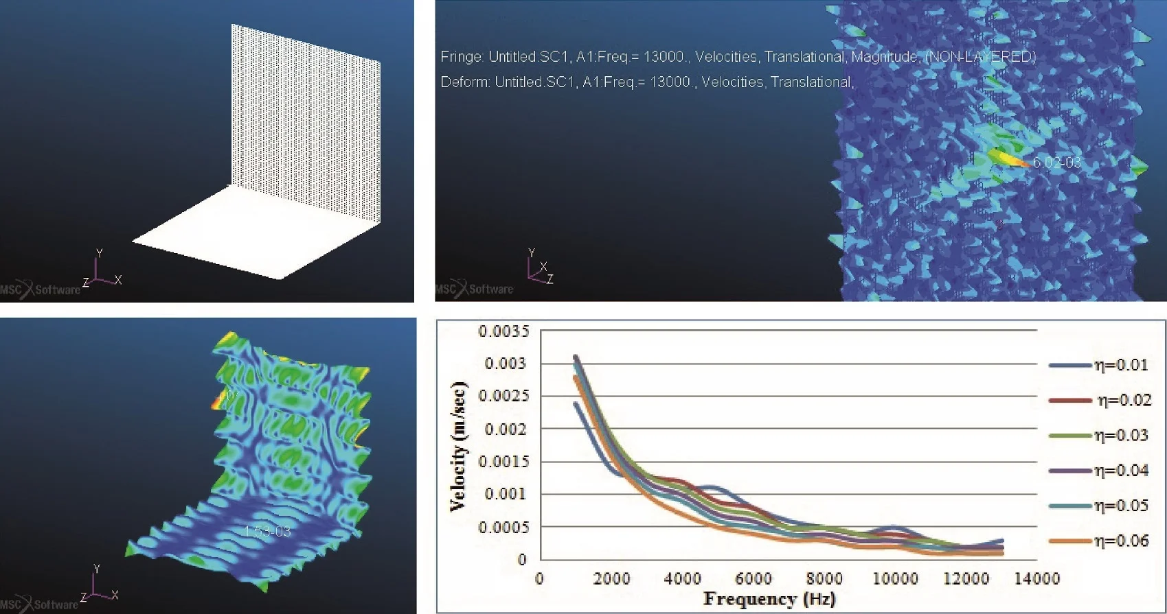
The numerical analysis of the L-shaped structure (Fig. 3) has been carried out using Nastran/Patran software [12]. The SEA parameters have been computed for various orientation of the fibre lay-up. The structure was meshed with quad 2D shell elements having orthotropic lay-up properties.
Fig. 3Finite element model
2D Shell element was used for analysing moderately thick plates having six degrees of freedom, comprising three translational and three-rotational. It can be used for modelling composite laminate with different orientations and variable thicknesses across the layers and also in modelling sandwich structures. Total of 20402 shell elements were created on both plate-1 and plate-2. The number of elements was considered based on the convergence criteria for numerical approach using Nastran/Patran software. The minimum element edge length [13] for numerical analysis should be less than one sixth of bending wave length ( and whichever is having least value). The calculated value for one sixth of bending wave length for the considered laminates was 0.015 m. The minimum edge length of the element used in the numerical approach (0.009 m) was less compared to the calculated value for one sixth of bending wave length.
A harmonic analysis with unit force was carried-out on the L-plate configuration, with a frequency range of 0-13000 Hz with an interval of 1000 Hz. The harmonic force is applied on first plate and vibration response on both the plates was computed. Velocity response at each node was determined on both the plates using Nastran/Patran. Post-processing was done by inversion technique [14] to compute velocity response on whole plate and coupling loss factors.
4. Results and discussion
Variation of SEA parameters, coupling loss factors and velocity of both the plates with frequency has been plotted. The results were computed for the considered frequency range. Vibration responses on both the plates were computed after applying a harmonic load on the first plate.
Fig. 4Variation of coupling loss factor vs frequency for different fibre orientation
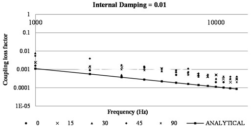
First a L-plate having a constant internal damping of 0.01 subjected to harmonic load was used and SEA parameters are computed using both analytical and numerical approach. The fibre orientation was varied from 0° to 90°. Fig. 4 shows the variation of coupling loss factor with change in frequency for different fibre orientation computed using both analytical and numerical approach. It was observed the coupling loss factor was not having any effect for change in fibre orientation when determined using analytical approach. For different fibre orientation considered from 0° to 90°,magnitude of coupling loss factor remained same for the given frequency in the analytical method. It was also observed that the coupling loss factor had a scatter with increase in frequency when determined using FEM. It is evident from the Fig. 4 that analytical equations are insensitive and cannot predict the coupling loss factor for change in fibre orientation.
Fig. 5Variation of velocity in plate 1 vs frequency for different fiber orientation
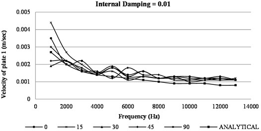
Fig. 5 shows variation of velocity in plate 1 with frequency. The graph is plotted for different fibre orientation. It can be observed from the graph that the velocity decreases with increase in frequency. This is because of the obvious reason that the amplitude of vibrations decreases at high frequencies as result of decrease in magnitude of average modal energy. Modal energy is proportional to square of the amplitude. Also, it can be seen that for different fibre orientations the velocity response computed numerically is scattered at the low frequencies and merges with analytically computed values at high frequencies. It can be observed that the velocity response computed analytically is independent of fibre orientation.
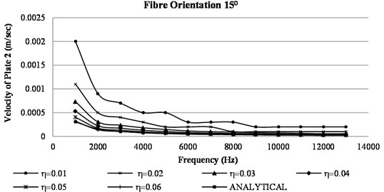
Fig. 6Variation of velocity in plate 2 vs frequency
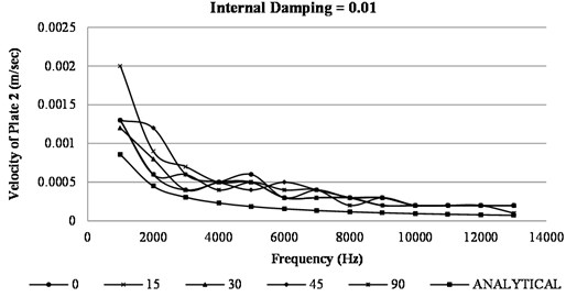
Fig. 6 shows variation of plate 2 velocity with frequency. In this case also, the computation of velocity response by analytical approach is independent of fibre orientation while numerical approach is able to capture the change in response with change in fibre orientation. Responses were computed on both the plates after applying harmonic load on plate 1; magnitude of velocity in plate 1 is higher compared to that of plate 2.
Fig. 7Variation of coupling loss factor vs frequency
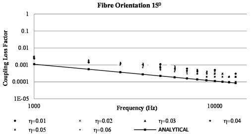
Further the impact of internal damping on SEA parameters is computed in Fig. 7, 8 and 9. The results are obtained by keeping the fibre orientation constant at 15° and internal damping was varied from 0.01 to 0.06 in an interval of 0.01. A L-plate configuration with a unit harmonic load applied on plate 1 was considered for computation of SEA parameters using analytical and numerical approach. Fig. 7 shows the impact of internal damping on coupling loss factor. It is evident from the graph that the coupling loss factor is autonomous of internal damping analytically. While comparing the analytical and numerical approach, there was some variation in the value of coupling loss factor seen at lower frequencies. At very high frequency the value coupling loss obtained by analytical and numerical computation almost merged.
Fig. 8 shows the variation of velocity in plate1 with frequency when internal damping was varied from 0.01 to 0.06. The graph shows the impact of internal damping for numerically computed values of plate 1 velocities. It can be inferred from the graph that, the velocity response in plate 1 obtained by analytical approach is independent of internal damping. It can also be seen that, with the increase in internal damping, the plate 1 velocity decreases for numerically computed values. As the internal damping increases more energy dissipation occurs in the subsystem. The analytically computed velocities of plate 1 were undisturbed by the internal damping values.
Fig. 8Variation of velocity in plate 1 vs frequency
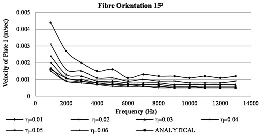
Fig. 9 shows variation of plate 2 velocity with frequency. In this case also the computation of velocity response by analytical approach is independent of internal damping. The results obtained by numerical approach were able to capture the change in response with change in internal damping. The harmonic force was applied on plate one and responses were computed on both plates, magnitude of velocity in plate 1 is higher compared to that of plate 2.
Fig. 9Variation of velocity in plate 2 vs frequency
Finally, the results obtained by both the approaches plotted in above figures show that analytical approach is insensitive to the change in fibre orientation and internal damping for SEA parameters. Numerical method, though time consuming, was able to capture the change in SEA parameters with the change in fibre orientation and internal damping. Thus, for predicting SEA parameters in composite materials numerical approach yields better results than that of analytical approach.
5. Conclusions
The results of velocity response and coupling loss factors were plotted for the L-plate. The parametric studies on the composite plate were carried. First the effect of fibre orientation on SEA parameters were computed both analytically and numerically. Later the effect of internal damping was studied. It can be observed that, the results obtained through analytical approach were independent of both fibre orientation and internal damping factor. The analytical approach does not take into account the change in fibre orientation and internal damping, while the numerical method is able to determine the SEA parameters appropriately. The analytical formulation was carried on the concept of conventional SEA. The conventional SEA is not efficient because of the lack of modal information at high frequencies. This modal information has to be determined analytically using discrete singular convolution method for the orthotropic plates which further increases the mathematical complexity of the structure. It becomes tedious and time consuming, while numerical method predicted more reliable results at ease. Hence the study reveals that for the orthotropic materials, and especially for the laminate structures, numerical method is appropriate compared to that of analytical method. It was observed that, the difference in velocity response of plate 1 and plate 2 was significantly high at low frequencies for both fibre orientation and internal damping. Though the differences in velocity response reduced at high frequencies after 7000 Hz, it showed significant difference in the value of coupling loss factor. Hence, to study the orthotropic materials especially the laminate structures, numerical method is appropriate compared to that of analytical method.
References
-
R. H. Lyon, Theory and Application of Statistical Energy Analysis. 2nd ed., Boston: Butterworth-Heinemann, 1995.
-
R. H. Lyon, “Statistical Energy Analysis of Dynamical Systems,” Massachusetts Institute of Technology, 1975.
-
T. D. Scharton and R. H. Lyon, “Power flow and energy sharing in random vibration,” The Journal of the Acoustical Society of America, Vol. 43, No. 6, pp. 1332–1343, Jun. 1968, https://doi.org/10.1121/1.1910990
-
D. E. Newland, “Power flow between a class of coupled oscillators,” The Journal of the Acoustical Society of America, Vol. 43, No. 3, pp. 553–559, Mar. 1968, https://doi.org/10.1121/1.1910865
-
R. H. Lyon and E. Eichler, “Random vibration of connected structures,” The Journal of the Acoustical Society of America, Vol. 36, No. 7, pp. 1344–1354, Jul. 1964, https://doi.org/10.1121/1.1919207
-
K. Shankar and A. J. Keane, “A study of the vibrational energies of two coupled beams by finite element and green function (receptance) methods,” Journal of Sound and Vibration, Vol. 181, No. 5, pp. 801–838, Apr. 1995, https://doi.org/10.1006/jsvi.1995.0172
-
A. Seçgin, “Numerical determination of statistical energy analysis parameters of directly coupled composite plates using a modal-based approach,” Journal of Sound and Vibration, Vol. 332, No. 2, pp. 361–377, Jan. 2013, https://doi.org/10.1016/j.jsv.2012.08.020
-
K. Shankar and A. J. Keane, “Vibrational energy flow analysis using a substructure approach: the application of receptance theory to FEA and SEA,” Journal of Sound and Vibration, Vol. 201, No. 4, pp. 491–513, Apr. 1997, https://doi.org/10.1006/jsvi.1996.0769
-
R. J. Pinnington and D. Lednik, “Transient energy flow between two coupled beams,” Journal of Sound and Vibration, Vol. 189, No. 2, pp. 265–287, Jan. 1996, https://doi.org/10.1006/jsvi.1996.0019
-
C. Hopkins, “Experimental statistical energy analysis of coupled plates with wave conversion at the junction,” Journal of Sound and Vibration, Vol. 322, No. 1-2, pp. 155–166, Apr. 2009, https://doi.org/10.1016/j.jsv.2008.10.025
-
S. N. Shastry and S. Subrahmanya Swamy, “Study on high frequency vibrations using statistical energy analysis for different composite materials,” IOP Conference Series: Materials Science and Engineering, Vol. 925, No. 1, p. 012044, Sep. 2020, https://doi.org/10.1088/1757-899x/925/1/012044
-
Nastran/Patran Version Manual. 2018.
-
C. Hopkins, “Statistical Energy Analysis of coupled plate systems with low modal density and low modal overlap,” Journal of Sound and Vibration, Vol. 251, No. 2, pp. 193–214, Mar. 2002, https://doi.org/10.1006/jsvi.2001.4002
-
V. Cotoni, P. Shorter, and R. Langley, “Numerical and experimental validation of a hybrid finite element-statistical energy analysis method,” The Journal of the Acoustical Society of America, Vol. 122, No. 1, pp. 259–270, Jul. 2007, https://doi.org/10.1121/1.2739420
About this article

