Abstract
To improve the dynamics of the face gear transmission system, a nonlinear dynamics model considering gyroscopic effects and including parameters such as time-varying meshing stiffness, meshing damping, tooth side clearance, support stiffness and damping is developed. The Runge-Kutta method was used to solve the nonlinear kinetic equations and analyze the accuracy and reasonableness of the model calculation results. The vibration displacement, vibration velocity and vibration acceleration along each direction of the face gear and straight cylindrical gear were analyzed, and the torsional vibration characteristics of the center of mass of the two gears were studied.
Highlights
- The dynamics of the orthogonal face gearing system is modeled, and the gyroscopic effect of the gears around their centers of mass during the face gearing process is considered in the model.
- The dynamical equations in the paper are solved using the Eulerian single-step method to analyze the nonlinear dynamical vibration characteristics of the face gearing system considering the gyroscopic effect.
- In this paper, the gyroscopic effect is considered and the vibration response of each degree of freedom of the gearing opposite to each parameter is analyzed.
1. Introduction
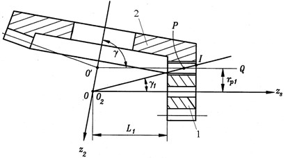
Face gear transmission is a cylindrical gear and bevel gear meshing gear transmission, its transmission principle is shown in Fig. 1, where the gear 1 for the involute straight cylindrical gear, gear 2 for the bevel gear, two-wheel axis intersection, its angle is . When the axis intersection angle 90 °, the bevel gear teeth will be distributed in a circular plane, the bevel gear is the face gear, and thus generally known as the face gear transmission.
Fig. 1Face gear transmission
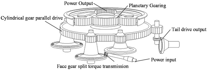
Face gears have the advantages of low vibration, low noise, high load-bearing capacity and simple structure [1-5]. In the ART program jointly carried out by the US. military and NASA in the 1990s, a new helicopter main gear using face gears for split-torsion transmission was designed, and face gears were used as the mechanism for split-torsion transmission in the main gear [6]. As shown in Fig. 2, the power output from the engine is shunted to two face gears by a cylindrical gear to realize the split-torsion transmission. Compared with the traditional helicopter main gear using bevel gear as the split-torsion transmission mechanism, the split-torsion transmission mechanism with face gear has a simple support structure and a weight reduction of about 40 %, and its power shunting effect is better, with less vibration and lower noise, which has obvious advantages over the bevel gear split-torsion transmission.
Fig. 2Helicopter main gearbox with face gear split-torsion drive
The current study of the dynamics of face gearing systems mainly uses the centralized parameter method [7-10],establishment of a bending-torsional coupled nonlinear dynamics model for an orthogonal gear train with time-varying meshing stiffness, meshing damping, tooth surface error, tooth surface friction, tooth side clearance, bearing clearance and other factors [11-15], solving the system of kinetic differential equations using the Runge-Kutta method, obtain the nonlinear vibration characteristics of the system and the influence of various parameters on the dynamic characteristics of the system, the swing of the two gears around their center of mass is not considered in the model [16-20]. In this paper, the dynamics of the face gear transmission system is modeled considering the gyroscopic effect. The influence of various parameters on the vibration of various degrees of freedom in face gear transmission system is analyzed, the model built is closer to the actual vibration of the face gear drive.
High speed is a trend of modern rotating machinery, and in the case of high speed, the gyroscopic effect cannot be ignored [21]. The gyroscopic effect is a physical phenomenon that occurs when the orientation of the symmetry axis of the rotor changes in high-speed rotating machinery. When the symmetry axis of the rotor is forced to change its orientation in space, that is, when the symmetry axis is forced to move, the rotor must act on the bearing an additional force couple, this phenomenon is the gyroscopic effect. The gyroscopic effect affects both the critical speed and stability of the rotor. To ensure safe and reliable operation of the machinery, it is necessary to consider the effect of the gyroscopic effect on rotor vibration [22]. The face gears studied in this paper are orthogonal face gears, and the face gears mentioned below all refer to orthogonal face gears.
2. System dynamics modeling
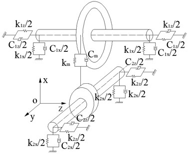
By using centralized parameters, the dynamic model of the orthogonal gear transmission system considering the gyro effect is established as shown in Fig. 3. The inertial coordinate system - belongs to the right-handed spiral coordinate system. When the gear is in a stationary state, the coordinate axis is parallel to the rotation axis of the driving straight cylindrical gear 2, and the coordinate axis is parallel to the rotation axis of the driven surface gear 1. Face gears and straight cylindrical gears are regarded as concentrated masses. The supports at both ends of the two gears are treated as elastic supports, and their support forms are treated as massless springs and dampers.
In order to study the dynamic characteristics of the orthogonal face gear transmission system, the dynamic coordinate systems - and - fixedly connected with the face gear and the straight cylindrical gear were established respectively, the coordinate origin and of the two-movement coordinate system are respectively at the center of mass of the face gear and the straight cylindrical gear. When the two gears are at rest, the coordinate axes of the moving coordinate system are parallel to the corresponding coordinate axes of the inertial coordinate system - which is:
Fig. 3Dynamic model of face gear transmission system
During the transmission of the face gear, the load on the face gear 1 can be decomposed into the axial component force parallel to the axis and the tangential component force parallel to the axis. Therefore, the center of mass o1 of the face gear 1 can freely vibrate in a plane parallel to the coordinate plane , and can rotate on a fixed axis relative to the center of mass , so the face gear 1 has two translational degrees of freedom and three rotational degrees of freedom. The force analysis of the face gear 1 is carried out. It is subjected to the reaction force and the reaction moment of the shaft 1, and the reaction force and the reaction moment of the straight cylindrical gear 2 to the face gear 1 (ignoring the friction between the tooth surfaces). According to the momentum theorem of the center of mass and the momentum moment theorem around the center of mass , we get:
where is the mass of the face gear 1; is the vector diameter of the face gear 1 center of mass with respect to the origin o of the inertial coordinate system, and its projection expression in the inertial coordinate system is ; is the inertia tensor of the face gear with respect to the dynamic coordinate system -, and its inertia matrix expression in the dynamic coordinate system -, considering the symmetry of the gear, is:
where is the angular velocity of the face gear 1, which is also the angular velocity of the dynamic coordinate system - with respect to the inertial coordinate system -, and its component expression in the dynamic coordinate system is . The reaction moment is the moment of the reaction force on the center of mass .
The expressions for the components of and in the inertial coordinate system are:
The expressions for the components of and in the dynamic coordinate system - are:
Rewriting Eqs. (1) and (2) into scalar form, the kinematic equation of the face gear 1 is obtained as:
Using the Eulerian parameter to describe the orientation of face gear 1 with respect to the inertial coordinate system, the kinematic equation of face gear 1 is:
The directional cosine matrix can be conveniently represented using Eulerian parameters:
A similar equation is obtained by the same analysis of straight cylindrical gear 2, corresponding to Eqs. (1) and (2):
Corresponding to Eqs. (8-12), there are:
Corresponding to Eq. (13), there are:
Corresponding to Eq. (14), there are:
3. Analytical calculation of , , and
is caused by the elastic bending of the face gear shaft 1, and in the case of very small bending deformation, its value can be found by the following relation:
where is a constant coefficient. If the effect of damping is considered, Eq. (15) can be changed to:
where is the damping coefficient, which is a function of or , and the function can be expressed by a polynomial:
where , and are constants.
consists of two parts. The first part is the driving torque transmitted from the face gear shaft 1 to the face gear. Its expression in the dynamic coordinate system - is:
The second part is the reaction moment caused by the bending of the face gear shaft 1. When the bending deformation is small, the expression of the second part of is:
where is a constant and is the angle representing the amount of bending deformation, which can be obtained by the following formula:
where represents the direction cosine matrix of the dynamic coordinate system relative to the inertial coordinate system. To find the direction of the moment, write and in plural form:
Then multiplying Eq. (21) by the complex number , we have:
Finally, the expression of the second part of in the moving coordinate system - is:
When , Eq. (23) does not hold, and at this time.
For straight cylindrical gear 2, a similar analysis can be carried out, corresponding to Eqs. (15-17), we have:
Corresponding to Eqs. (18) and (23), we have
where is the load torque of the straight cylindrical gear shaft 2 acting on the straight cylindrical gear. The represents the direction cosine matrix of the dynamic coordinate system 2 relative to the inertial coordinate system.
3.1. Calculation of , and
is the meshing force between face gear 1 and straight cylindrical gear 2, and its mathematical model is:
where is the time-varying meshing stiffness; is the meshing damping; is the relative displacement along the meshing line; is the clearance function, and its expression is:
where is half of the average normal mesh clearance of gear pair.
The expression of the time-varying meshing stiffness can be approximated as:
where is the average meshing stiffness; is the vibration amplitude of the meshing stiffness; is the meshing angular frequency; is the initial phase of the engagement stiffness, usually zero.
The expression for the relative displacement along the direction of the engagement line is:
where is the base circle radius of the straight cylindrical gear; is the meshing radius of the face gear; is the meshing angle of the gear pair; is the comprehensive transmission error of the gear pair, and its expression is:
where is the average comprehensive error; is the fluctuation amplitude of the comprehensive error; is the initial phase of the comprehensive error; and are the angles of rotation of axis 1 and axis 2 respectively, the expression is:
The magnitude of the meshing force is analyzed above, and the unit vector of its direction is denoted as .In the actual meshing transmission process of the face gear, the direction of the meshing point and the meshing line are complex functions that change with time. To facilitate the analysis of its dynamics, assume that the point of engagement and the direction of the line of engagement do not change with time. Then the expression of the unit vector in the inertial coordinate system is:
The components of vectors and in the moving coordinate system - and - are expressed as:
According to the definition of torque, the expressions of and are respectively:
4. System dynamics analysis
The above dynamic equations are solved using Euler’s single-step method [23], and the nonlinear dynamic vibration characteristics of the face gear transmission system considering the gyro effect are analyzed. When solving, the parameters of the face gear transmission system are shown in Table 1. The support stiffness and damping in the table are selected from references [24] and [25].
Table 1Parameter table of face gear transmission system
Symbol | Quantity | Numerical value |
Number of face gear teeth | 120 | |
Number of cylindrical gear teeth | 40 | |
Gear module | 3 mm | |
Pressure angle | 25° | |
Tooth width | 25 mm | |
Input power | 10 Kw | |
Quality of straight cylindrical gear | 2.65 kg | |
Quality of face gear | 7.72 kg | |
Face gear support stiffness | 5×10⁹ N/m | |
Straight cylindrical gear support stiffness | 4×10⁹ N/m | |
Face gear support damping | 4×10⁵ N·s·m-1 | |
Straight cylindrical gear support damping | 3×10⁵ N·s·m-1 | |
Average meshing stiffness | 3×10⁸ N/m | |
Engagement damping | 1×10⁵ N·s·m-1 | |
Input speed | 3000 r/min |
Fig. 4Vibration displacement along x-axis direction
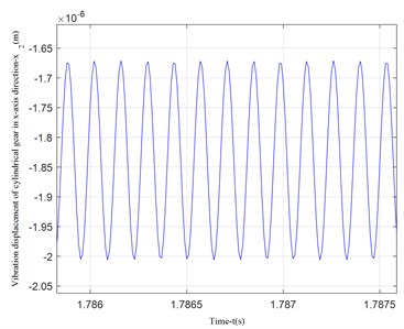
a) Vibration displacement in -axis direction of cylindrical gear
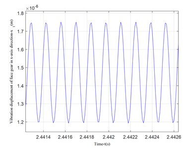
b) Vibration displacement in -axis direction of face gear
It can be seen from Fig. 4 that the vibration displacement of the face gear is about 1/3 larger than the vibration displacement of the straight cylindrical gear. Because the cylindrical gear in the model has a smaller bending moment and smaller deformation, the calculation results are in line with engineering reality. Comparing the vibration displacement in the -axis and -axis directions of the face gear in Figs. 4 and 5, the vibration displacement in the -axis direction of the face gear is smaller than the vibration displacement in the -axis direction, this is because the component force of the meshing force in the x-axis direction is small, and the calculation result is consistent with the force analysis result.
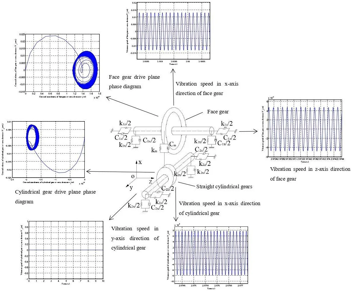
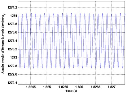
According to the analysis in Fig. 6, it can be seen that the vibration speed period of the -axis and -axis of the face gear is the same. However, the vibration velocity in the -axis direction is greater than that in the -axis direction, which is consistent with the vibration displacement analysis results of Figs. 4 and 5.Fig. 7 shows the vibration velocity of the cylindrical gear in the -axis and -axis directions, the vibration velocity in the -axis direction of the cylindrical gear and the vibration velocity in the -axis direction of the face gear in Fig. 6 are both periodic vibrations, the vibration speed in the -axis direction is a straight line. This is due to the transmission characteristics of the face gear. The face gear and the cylindrical gear are not stressed in the y-axis direction, so no vibration will occur.
Fig. 5Vibration displacement in the z-axis direction of the face gear
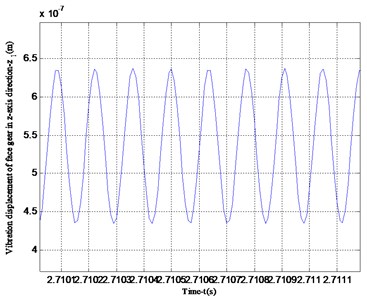
Fig. 6Vibration speed of face gear in x-axis and z-axis directions
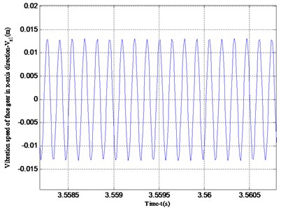
a) Vibration speed in -axis direction of face gear
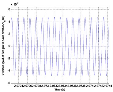
b) Vibration speed in -axis direction of face gear
Fig. 7Vibration speed in the x-axis and y-axis directions of the cylindrical gear
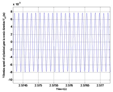
a) Vibration speed in -axis direction of cylindrical gear
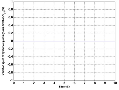
b) Vibration speed in -axis direction of cylindrical gear
Fig. 8 shows the vibration acceleration of the straight cylindrical gear in the -axis and -axis directions. Since the straight cylindrical gear does not vibrate in the -axis direction, its vibration acceleration is 0, and the period of the vibration velocity is the same as that in Fig. 7. Figs. 9 and 10 are the angular velocity and angular acceleration of the torsional vibration of the center of mass of the face gear and the straight cylindrical gear around the -axis. Since the gear ratio of the face gear and the straight cylindrical gear is 3, the calculation result has a period ratio of 3, which is consistent with the actual result.
Fig. 8Vibration acceleration in the x-axis and y-axis directions of the cylindrical gear
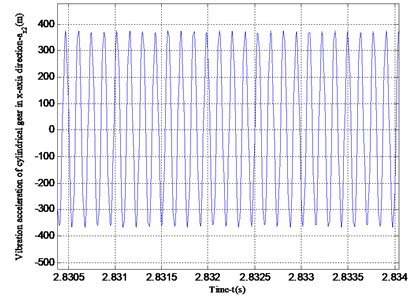
a) Vibration acceleration in -axis direction of cylindrical gear
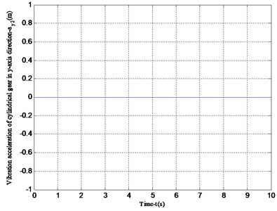
b) Vibration acceleration in -axis direction of cylindrical gear
Fig. 9Angular velocity and angular acceleration of face gear vibrating around the y-axis
a) Angular velocity of face gear vibration around -axis

b) Angular acceleration of face gear vibration around -axis
Fig. 10Angular velocity and angular acceleration of cylindrical gear vibrating around the y-axis
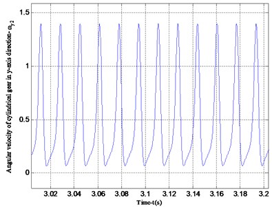
a) Angular velocity of cylindrical gear vibrating around -axis
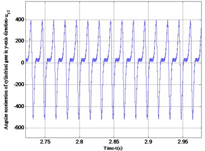
b) Angular acceleration of cylindrical gear vibration around -axis
Fig. 11Plane phase diagram of the vibration of the face gear transmission system
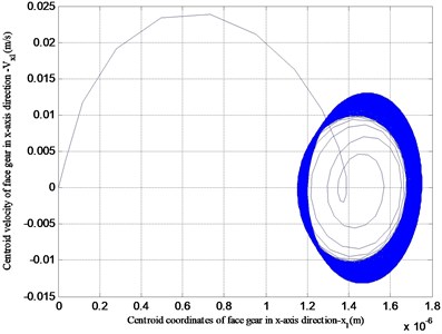
a) Face gear drive plane phase diagram
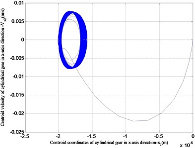
b) Cylindrical gear drive plane phase diagram
Fig. 11 is a plane phase diagram of the x-coordinate of the center of mass of the face gear transmission system. The -coordinates of the straight cylindrical gear and the face gear have a large change when starting, but tend to be stable after stable operation, which is consistent with engineering practice.
According to the above vibration characteristics of the face gear obtained by numerical analysis considering the gyroscopic effect, compared with the results of the vibration characteristics of the face gear without considering the gyroscopic effect in the literature [25-27], it can be seen that the vibration displacement, vibration velocity, and vibration angular velocity are relatively small in the face gear drive with high speed. According to the plane phase diagram of the center of mass, it can be seen that the face gear and the cylindrical gear gradually stabilize within a relatively small vibration displacement. Therefore, it is necessary to consider gyroscopic effects in high speed face gear drives.
5. Conclusions
Establish a dynamic model of the orthogonal face gear transmission system. The gyro effect of the gear around its center of mass during the face gear transmission is considered in the model. It also includes time-varying meshing stiffness, tooth surface error, support stiffness, support damping and other factors, which can more comprehensively describe the vibration characteristics of face gear transmission.
Adopt Euler parameter method to establish the nonlinear dynamic equation of the face gear transmission system considering the gyro effect and solve it to obtain the dynamic response characteristics of the face gear transmission system.
The vibration characteristics of the face gear transmission system are more complicated, and it is very important for the high-speed and heavy-duty helicopter transmission system. Therefore, it is particularly important to establish a dynamic model that can better reflect the real working conditions, and it has important theoretical guiding significance for improving the stability, service life and the vibration and noise reduction of the system.
References
-
Handschud R. F., Lewicki D. G., and Bossler R. B., “Experimental Testing of Prototype Face Gears for Helicopter Transmissions,” NASA-TM-105434, 1992.
-
F. L. Litvin, J.-C. Wang, R. B. J. Bossler, Y.-J. D. Chen, G. Heath, and D. G. Lewicki, “Application of face-gear drives in helicopter transmissions,” in International Power Transmission and Gearing Conference, Sep. 2013.
-
F. L. Litvin, J.-C. Wang, R. B. Bossler, Y.-J. D. Chen, G. Heath, and D. G. Lewicki, “Application of face-gear drives in helicopter transmissions,” Journal of Mechanical Design, Vol. 116, No. 3, pp. 672–676, Sep. 1994, https://doi.org/10.1115/1.2919434
-
F. L. Litvin, C.-L. Hsiao, J.-C. Wang, and X. Zhou, “Computerized simulation of generation of internal involute gears and their assembly,” Journal of Mechanical Design, Vol. 116, No. 3, pp. 683–689, Sep. 1994, https://doi.org/10.1115/1.2919436
-
F. L. Litvin, A. Egelja, J. Tan, and G. Heath, “Computerized design, generation and simulation of meshing of orthogonal offset face-gear drive with a spur involute pinion with localized bearing contact,” Mechanism and Machine Theory, Vol. 33, No. 1-2, pp. 87–102, Jan. 1998, https://doi.org/10.1016/s0094-114x(97)00022-0
-
D. G. Lewicki, R. F. Handschuh, G. F. Heath, and V. Sheth, “Evaluation of Carburized and Ground Face Gears,” NASA-TM-1999-209188, Sep. 2013.
-
Y. Chen and R. Bossler, “Design, analysis, and testing methods for a split-torque face-gear transmission,” in 31st Joint Propulsion Conference and Exhibit, Jul. 1995, https://doi.org/10.2514/6.1995-3051
-
Chung T. D. and Chang S. H., “The undercutting and pointing of face gear,” Journal of the Chinese Institute of Engineering, Vol. 21, No. 2, 1998.
-
Andrei G., “Advanced face gear technology for rotorcraft drive trains,” in Proceedings of the 24th European Rotorcraft Forum, 1998.
-
Chang S. H. and Chung S. D., “Analysis of the kinematic error of a face gear harmonic drive,” Chinese Society of Mechanical Engineering, Vol. 19, No. 4, 1998.
-
Litvin F. L., “Apparatus and method for precision grinding face gear,” America US006146253-A-[P], 2000.
-
F. L. Litvin, A. Egelja, J. Tan, D. Y.-D. Chen, and G. Heath, “Handbook on Face Gear Drives with a Spur Involute Pinion,” NASA CR-209909, Sep. 2013.
-
Frąckowiak, P., Ptaszyński, W., Stoić, and A., “New geometry and technology forming face-gear with circle line of teeth on CNC milling machine,” Metalurgija, Vol. 51, No. 1, pp. 109–112, 2012.
-
X.-Z. Deng, G.-G. Li, B.-Y. Wei, and J. Deng, “Face-milling spiral bevel gear tooth surfaces by application of 5-axis CNC machine tool,” The International Journal of Advanced Manufacturing Technology, Vol. 71, No. 5-8, pp. 1049–1057, Mar. 2014, https://doi.org/10.1007/s00170-013-5499-3
-
Z. C. Chen and M. Wasif, “A generic and theoretical approach to programming and post-processing for hypoid gear machining on multi-axis CNC face-milling machines,” The International Journal of Advanced Manufacturing Technology, Vol. 81, No. 1-4, pp. 135–148, Oct. 2015, https://doi.org/10.1007/s00170-015-7171-6
-
D. Liu, T. Ren, and X. Jin, “Geometrical model and tooth analysis of undulating face gear,” Mechanism and Machine Theory, Vol. 86, pp. 140–155, Apr. 2015, https://doi.org/10.1016/j.mechmachtheory.2014.12.004
-
Y. Wang, Z. Lan, L. Hou, H. Zhao, and Y. Zhong, “A precision generating grinding method for face gear using CBN wheel,” The International Journal of Advanced Manufacturing Technology, Vol. 79, No. 9-12, pp. 1839–1848, Aug. 2015, https://doi.org/10.1007/s00170-015-6962-0
-
X.-L. Peng, L. Zhang, and Z.-D. Fang, “Manufacturing process for a face gear drive with local bearing contact and controllable unloaded meshing performance based on ease-off surface modification,” Journal of Mechanical Design, Vol. 138, No. 4, Apr. 2016, https://doi.org/10.1115/1.4032579
-
K. Kawasaki, H. Gunbara, and H. Tamur, “Study of meshing of gear teeth,” in Proc. of JSME International Conference on Motion and Power Transmissions, pp. 82–86, 2009.
-
I. Tsuji, H. Gunbara, K. Kawasaki, and A. Takami, “Machining and running test of high-performance face gear set,” in ASME 2011 International Design Engineering Technical Conferences and Computers and Information in Engineering Conference, Jan. 2011, https://doi.org/10.1115/detc2011-48824
-
Sui Yongfeng and Lv Hexiang, “Influence of gyroscopic term to the vibration of rotor system,” (in Chinese), Chinese Journal of Computational Mechanics, Vol. 6, pp. 711–714, 2003.
-
Liu Weijia, “Impact of gyroscopic effect on the critical speed of the rotor,” (in Chinese), Journal of Jilin Normal University, Vol. 33, No. 3, pp. 47–49, 2012.
-
Wen Bangchun, Theory of Mechanical Vibration and Its Applications. (in Chinese), Beijing: Higher Education Press, 2009.
-
Li Xiaozhen, Zhu Rupeng, Li Zhengminqing, and Jin Guanghu, “Influences of frictional coefficient on vibration characteristic of face-gear transmission system,” (in Chinese), Zhendong Gongcheng Xuebao, Vol. 27, No. 4, pp. 583–588, 2014.
-
Yang Zhen, Wang Sanmin, Fan Yeseng, and Liu Haixia, “Nonlinear dynamics of face-gear transmission system,” (in Chinese), Journal of Vibration and Shock, Vol. 29, No. 9, pp. 218–221, 2010.
-
Lin Tengjiao and Ran Xiongtao, “Nonlinear vibration characteristic analysis of a face-gear drive,” (in Chinese), Zhendong yu Chongji, Vol. 31, No. 2, pp. 25–31, 2012.
-
Jin Guanghu, Zhu Rupeng, and Bao Heyun, “Nonlinear dynamical characteristics of face gear transmission system,” (in Chinese), Journal of Central South University (Science and Technology), Vol. 41, No. 5, pp. 1807–1813, 2010.
Cited by
About this article

This work is supported by the Spent Fuel Dissolver Project of the Ministry of Nuclear Industry of the People’s Republic of China.
