Abstract
Transmission error is the main excitation source of gear vibration and noise, how to reduce the transmission error has always been the focus of the research on gear dynamics. In this study, a new type of cylindrical spur gear with elastic isolation is developed for the reduction of transmission error. The elastic isolation damping gear includes three parts: the gear body, the elastic isolation layer, and the involute profile body. Dynamic models are established with the elastic isolation damping gear using lumped parameter method. Dynamic characteristics are simulated via spur gear pair examples by the Runge-Kutta algorithm. By comparing the simulation results of three gear models, the dynamic response of the elastic isolation damping gear with sliding friction is illustrated. The influence of different parameters of the elastic isolation layer on the dynamic response for the elastic isolation damping gear model is carried out. The results indicate that the proposed elastic isolation damping gear model is effective in reducing dynamic transmission error, especially for torque fluctuation, high-speed and heavy-duty conditions. Parameter influence analysis guides the design of elastic isolation damping gears with low transmission error.
1. Introduction
Due to high transmission efficiency and stability, gears play an important role in mechanical transmission. In the process of gear meshing, it is inevitable to excite vibration and noise, which is very annoying. To improve the dynamic stability of gear transmission, how to effectively reduce the vibration of gear is particularly important.
It is generally considered that transmission error is the main excitation source of gear vibration and noise [1-4]. Karagiannis et al. [5] presented a torsional dynamic modeling method of hypoid gear pairs, this method adopts an alternative expression of dynamic transmission error. He et al. [6-7] analytically examined the effect of the profile modification on the dynamic transmission error of spur gears, and predicted the dynamic transmission error using Floquet theory. Tesfahunegn et al. [8] investigated the effect of the shape of relief on the stresses and transmission error. Wei et al. [9] studied the effects of bearing supporting stiffness, mesh damping and backlash on the dynamic transmission errors of helical gears. Velex et al. [10] analyzed the relationship between dynamic mesh excitation and transmission error, and proved that the dynamic mesh force is mainly controlled by local transmission error. Sánchez et al. [11] studied the effects of the amount, length, and shape of the profile modification on the transmission error based on a developed mesh stiffness approximate equation. Zhang et al. [12] presented a loaded tooth contact analysis, which reveals the sensitivity of gear tooth modification parameters to transmission error fluctuations. Pleguezuelos et al. [13] presented a simple analytical model for the transmission error for spur gears with profile modification under non-nominal load conditions. Bruzzone et al. [14] established a bi-dimensional approach under quasi-static conditions to model the deflection and the load sharing characteristics of spur gears, and investigated the effects of different profile modifications on the static transmission error. Lee et al. [15] establish a robust algorithm to analyze the influence of system uncertainties on the transmission error of a spur gear pair. The algorithm provides a way of generating smooth cutter profiles with machining uncertainties and measuring the thermal deformation. Jiang et al. [16] developed a dynamic model of helical gears with coupled sliding friction, the results show that the oscillations of the dynamic transmission error become more significant incorporating the effects of coupled sliding friction. Benaicha et al. [17] provided an insight into the efficiency and accuracy of a multibody approach to model gear transmission error, the proposed methodology can include micro-geometry deviations, additional flexible mechanical components and specific design of the gear body.
Numerous research and studies attempt to reduce vibration and noise by reducing transmission error of gear transmission [18-21]. Litvin et al. [22] presented two original symmetric profile modification analysis formulas to minimize the fluctuations of transmission error. Astoul et al. [23] proposed an optimization design method based on loaded tooth contact analysis to reduce the transmission error of spiral bevel gears. Besharati et al. [24] developed a new design of a backlash elimination gear mechanism to reduce dynamic transmission error. The results show that when all teeth are rigid and the static transmission error can be ignored, the dynamic transmission error is zero for each input torque. Ghosh and Chakraborty [25] studied the effect of profile modification on reducing gear noise and vibration levels. Mehmet [26] presented the optimization of gearbox geometric design parameters based on a transmission error to reduce gear-rattle noise. The results show that the optimized geometric design parameters reduce the rattle noise level by 10 % [dB]. Bruyere et al. [27] developed a closed-form formula incorporating the profile relief and lead crown to minimized the amplitudes of transmission error. The results show that the best modification is roughly located in the line segment of the relief and crown plane. Pleguezuelos et al. [28] studied the quasi-static transmission error of high contact ratio spur gears with symmetric long profile modifications, the tip relief for the minimum peak-to-peak amplitude of quasi-static transmission error has been obtained. And later they presented a simple analytical model for the transmission error for spur gears with profile modification under non-nominal load conditions. Choi et al. [29] optimized the gear macro-geometry of a 75 kW agricultural tractor transmission through a genetic algorithm to minimize peak-to-peak static transmission error. Mu et al. [30] proposed an innovative ease-off flank modification method to reduce the running vibration of spiral bevel gear, the numerical results show that the modification method can reduce the loaded transmission error which improves the dynamic performance.
Previous research was concentrated on the influence of profile relief, geometric design parameters and lead crown on the reduction of transmission error of normal spur gears. However, combined new spur gears may be another method to reduce the gear transmission error, thereby reducing gear vibration and noise. For this purpose, a new type of cylindrical spur gear with elastic isolation is proposed in this study, which attempts to use the function of the elastic isolation layer to reduce the vibration and noise of gear transmission based on the reduction of transmission error.
2. Structure of an elastic isolation damping gear
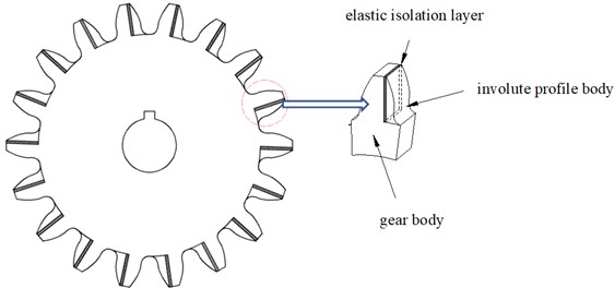
In this paper, a new type of cylindrical spur gear with elastic isolation is proposed. The schematic diagram of the elastic isolation damping gear is shown in Fig. 1, which is composed of three parts: the gear body, the elastic isolation layer and the involute profile body. The gear body is assumed to be rigid with elastic movable teeth, and the teeth are all standard involute tooth profiles. The elastic isolation layer is a kind of damping material, which has the function of reducing vibration and noise. In this model, the elastic isolation layer is sealed between the gear body and the involute profile body, so that the gear body, the elastic isolation layer and the involute profile body form a new gear tooth (named the elastic isolation damping gear tooth). When one or a pair of elastic isolation damping gears are used, the gear body drives the elastic isolation layer to rotate, and the elastic isolation layer drives the involute profile body to rotate. The involute profile body of the two gears are meshed with each other to transmit motion or power, and then, a gear transmission system with elastic isolation damping gear is formed.
Fig. 1Schematic diagram of an elastic isolation damping gear
3. Dynamic modeling
3.1. Dynamic modeling of a pair of elastic isolation damping gears
If the two transmission gears used are both elastic isolation damping gear, a pair of elastic isolation damping gear is formed. The schematic diagram of a pair of elastic isolation damping gears is plotted in Fig. 2.
Fig. 2Schematic diagram of a pair of elastic isolation damping gears
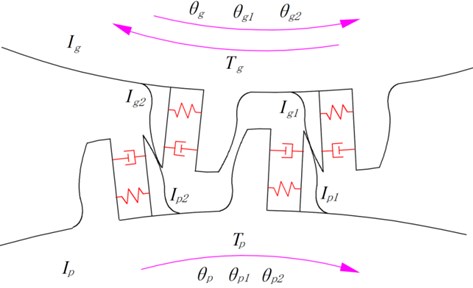
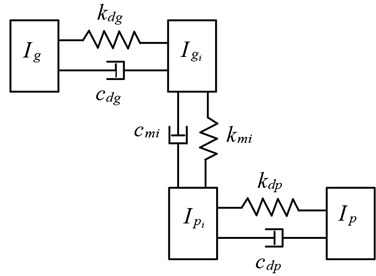
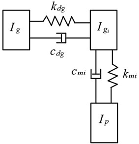
Since there is a slight torsional vibration between the involute profile body and the gear body during rotation, the elastic isolation layer is approximated as torsional stiffness and torsional damping. Then, the equivalent dynamic model of a pair of elastic isolation damping gears by using lumped parameter method can be plotted as Fig. 3. The vibration system is shown in Fig. 3, and represent the moment of inertia of the gear body. and denote the moment of inertia of the th meshing involute profile body, respectively. By defining , , , , , to be the angular displacement of the six inertia elements, the equation of motion of the elastic isolation damping gear system is derived as:
where, , , , represent the torsional damping and torsional stiffness of the elastic isolation layer, respectively. and are the base circle radius of the pinion and gear. denote the frictional forces between the th meshing involute profile body. and are the moment arm of the friction force acting on the th meshing involute profile body. and are the input torque and output torque, which can be expressed by Fourier series as follows:
here is the average part of the input torque. , and are the amplitude ratio corresponding to the vibration part of the harmonic, the initial phase of the th harmonic, and the excitation frequency respectively.
Fig. 3Equivalent dynamic model of a pair of elastic isolation damping gears
The dynamic mesh forces of the th meshing involute profile body can be deduced as:
here, and represent the mesh damping and mesh stiffness of the th meshing involute profile body.
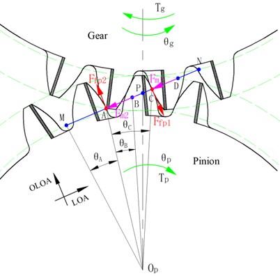
The meshing process of elastic isolation damping gears can be represented in Fig. 4. During the operation of the gear, there will be single-tooth meshing and double-tooth meshing alternately. The time-varying mesh stiffness of gear teeth can be calculated by the following formula [31]:
where, , is the number of teeth of the pinion. and are the mesh stiffness of the double-tooth contact and single-tooth contact respectively. It can be concluded from Fig. 4 that the angles can be given as:
here, is the contact ratio, represents the base pitch, is the radius of the addendum circle of the pinion.
Fig. 4Meshing process of elastic isolation damping gears
The frictional force between the th meshing involute profile body can be expressed as:
here, is the friction coefficient and the relative sliding velocity of th meshing involute profile body are given as:
The moment arm of the friction force of the meshing involute profile body is expressed as:
where, is the length of the theoretical meshing line.
The relative dynamic displacement of the pinion and gear along the line of action (LOA) is defined as the dynamic transmission error (DTE), which can be calculated as [32]:
3.2. Dynamic modeling of combined elastic isolation damping gears
If one of the gears used is a normal spur gear and the other is an elastic isolation damping gear, a pair of combined elastic isolation damping gear transmission is formed, as can be seen from Fig. 5. In this model, assuming the pinion to be a normal spur gear while the gear to be an elastic isolation damping gear. The equivalent dynamic model of combined elastic isolation damping gears is plotted in Fig. 6. Similarly, the governing equations of the combined isolation damping gear system are:
Fig. 5Schematic diagram of combined elastic isolation damping gears
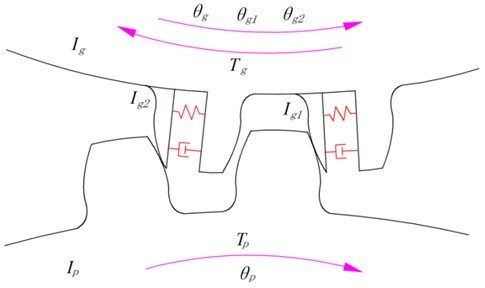
Fig. 6Equivalent dynamic model of combined elastic isolation damping gears
3.3. Dynamic modeling of normal spur gears
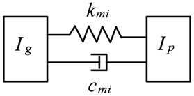
Without elastic isolation damping gear, the transmission system is formed by normal spur gears. The schematic diagram and equivalent dynamic model of normal spur gears are plotted in Fig. 7 and Fig. 8. The torsional vibration equations of the normal spur gears can be given as:
where, and are the moment arm of the friction force for the normal spur gears, the calculation equations can be found in Ref. [30].
Fig. 7Schematic diagram of normal spur gears
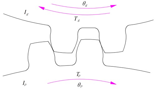
Fig. 8Equivalent dynamic model of normal spur gears
4. Results and discussion
The parameter of the spur gear system in this study are listed in Table 1. 4th-5th order Runge-Kutta algorithm has been used to numerical integral the governing equations. To illustrate the influence of elastic isolation damping gear on the dynamic transmission error of gear system, simulation results from three models have been compared in this section: (a) the first model is a pair of normal spur gears; (b) the second model is the combined elastic isolation damping gears (CEIDG) with only the gear is represented by an elastic isolation damping gear; (c) the third model is a pair of elastic isolation damping gears (APEIDG). The dynamic response for spur gears considering the effect of elastic isolation damping gear will be illustrated.
Table 1Parameters of spur gear system
Parameter/property | Pinion | Gear |
Number of teeth | 19 | 48 |
Module | 2 | |
Pressure angle, deg | 20 | |
Polar moment of inertia, kg.m2 | 4.3659×10⁻⁴ | 8.3602×10⁻³ |
Contact ratio | 1.6456 | |
Gear mesh stiffness, N/m | 10.3×10⁸ | |
6.2×10⁸ | ||
Input torque (N.m) | 200 | |
Rotation speed of pinion (rpm) | 900 | |
4.1. Comparison of different gear models
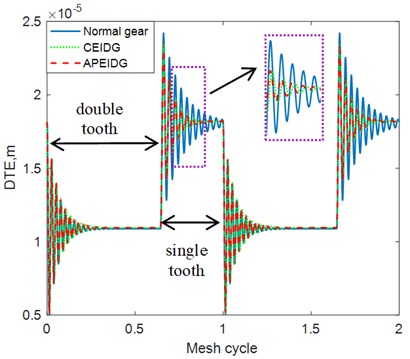
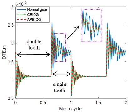
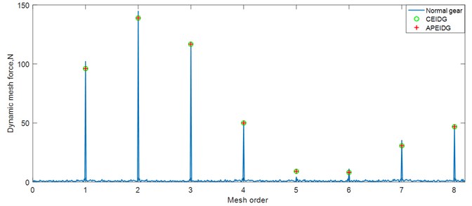
The dynamic transmission error with different gear models under constant torque conditions are plotted in Fig. 9. It can be observed from the comparison of the results that the effect of the elastic isolation damping gear greatly reduces the dynamic transmission error of the single-tooth contact area, while the effect on the double-tooth contact area is not obvious. There is almost no difference between the results of a pair of elastic isolation damping gears model and the combined elastic isolation damping gear model. Taking into account the effect of sliding friction on the tooth surface, additional oscillations occur in the dynamic transmission error on the left and right sides of the pitch point. This is consistent with the trend of the results verified in Ref. [33]. When comes to the fluctuation torque condition, amplitude modulation appears in the dynamic transmission error results as can be seen from Fig. 10. The effect of the elastic isolation damping gear not only reduces the dynamic transmission error of the single-tooth contact area, but also reduces the oscillation before the transition from the double-tooth contact area to the single-tooth contact area. In other words, the vibration reduction of the elastic isolation damping gear is more obvious under the working state of torque fluctuation. The time and frequency domain results of the dynamic mesh force with different gear models under constant torque conditions are plotted in Fig. 11 and Fig. 12. Similar phenomena can be observed in the time domain results of the dynamic mesh force. The effect of the elastic isolation damping gear reduces the dynamic mesh force of the single-tooth contact area, which is beneficial to improve the load-carrying capacity of a single tooth. From the frequency domain results of the dynamic mesh force in Fig. 12, it is observed that the effect of the elastic isolation damping gear mainly reduced the amplitude of the first two mesh frequencies of the dynamic mesh force.
Fig. 9Comparison of dynamic transmission error with three gear models (constant torque)
a) Without friction
b) With friction
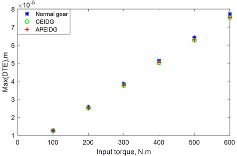
To study the effect of rotational speed and input torque on the dynamic transmission error, several rotational speeds and input torques are used in the dynamic models. The effects of rotational speed and input torque on the dynamic transmission error with different gear models are plotted in Fig. 11 and Fig. 12. It can be seen from Fig. 11, the maximum value of the transmission error increase with increasing rotational speed for the three gear models at the low speeds (0-750 RPM), while reducing with the increasing rotational speed at the medium speeds (750-1500 RPM). When the rotational speed reaches high speed (1500-2500 RPM), the dynamic transmission error presents different changes for the three gear models. For the normal spur gears, the maximum value of the dynamic transmission error suddenly increases to a large value, while for the two models with elastic isolation damping gear, the maximum value of the dynamic transmission error is further reduced to a smaller value. This shows that the elastic isolation damping gear has a more significant effect on reducing dynamic transmission errors at high speeds. It can be seen from Fig. 12, the maximum value of the transmission error increase with increasing input torque for the three gear models. As the torque increases, the effect of the elastic isolation damping gear in reducing the dynamic transmission error becomes more obvious. It is observed that the maximum dynamic transmission error of the combined elastic isolation damping gear model is slightly smaller than the results of the gear model with a pair of elastic isolation damping gears. Therefore, the combined elastic isolation damping gears model can better achieve the purpose of reducing dynamic transmission errors.
Fig. 10Comparison of dynamic transmission error with three gear models (fluctuation torque)
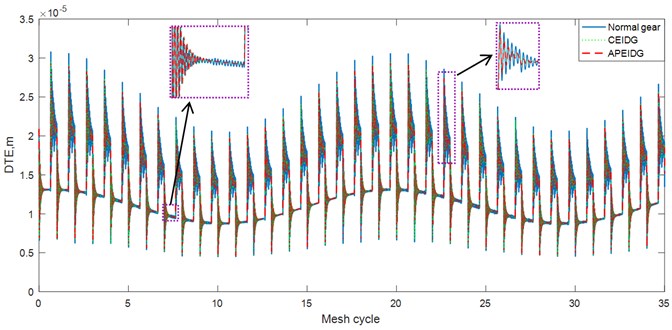
Fig. 11Comparison of dynamic mesh force with three gear models (time domain)
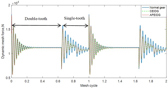
Fig. 12Comparison of dynamic mesh force with three gear models (frequency domain)
4.2. Effect of torsional stiffness and torsional damping of the elastic isolation layer
To study the influence of different parameters of the elastic isolation layer on the dynamic responses of the elastic isolation damping gear model, several torsional stiffnesses and torsional damping of the elastic isolation layer are used in the combined elastic isolation damping gear model. The effects of torsional stiffness and torsional damping of the elastic isolation layer on the dynamic transmission error are plotted in Fig. 13 and Fig. 14.
Fig. 13Effect of rotational speed on dynamic transmission error with different gear models
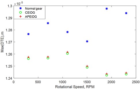
Fig. 14Effect of input torque on the dynamic transmission error with different gear models
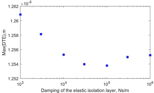
It can be seen from Fig. 15, the maximum value of the transmission error reduces quickly with increased torsional stiffness of the elastic isolation layer at the beginning (107-108N/m). When the torsional stiffness of the elastic isolation layer increases from 108 to 109 N/m, the reduction of maximum dynamic transmission error is very slow. When the torsional stiffness of the elastic isolation layer exceeds 109 N/m, the maximum value of the dynamic transmission error hardly changes. It can be seen from Fig. 16, the maximum value of the transmission error reduces quickly with increasing torsional damping of the elastic isolation layer at the beginning (103-104Ns/m). When the torsional damping of the elastic isolation layer increases from 104 to 105 N/m, the reduction of maximum dynamic transmission error is very slow. When the torsional stiffness of the elastic isolation layer exceeds 105 N/m, the maximum value of the transmission error increases with increasing torsional damping of the elastic isolation layer. The results show that the dynamic transmission error does not monotonously increase or decrease with the increase of torsional stiffness and torsional damping of the elastic vibration isolation layer. It is necessary to select the parameters reasonably during the design to minimize the dynamic transmission error for the combined elastic isolation damping gears.
Fig. 15Dynamic transmission error with various stiffness of the elastic isolation layer
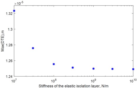
Fig. 16Dynamic transmission error with various damping of the elastic isolation layer
5. Conclusions
The main contribution of this paper is to develop a new type of spur gear with elastic isolation to reduce transmission errors. Gear dynamic models are established with elastic isolation damping gear based on lumped parameter method. Dynamics simulations are carried out by using the Runge-Kutta algorithm. The results illustrate the dynamic response for the gear dynamic models with elastic isolation damping gear. Conclusions can be drawn as follows.
The effect of the elastic isolation damping gear greatly reduces the dynamic transmission error of the single-tooth contact area, the reduction of dynamic transmission error becomes more significant under torque fluctuation, high-speed and heavy-duty conditions. The combined elastic isolation damping gear model can better achieve the purpose of reducing dynamic transmission errors compared with the other two gear models. The effect of the elastic isolation damping gear reduces the dynamic mesh force which is beneficial to improve the load-carrying capacity of the contact tooth. The investigation of the effect of torsional stiffness and torsional damping of the elastic isolation layer on dynamic transmission error guides for the design of combined elastic isolation damping gears with low transmission error. Reasonable selection of parameters can reduce the vibration level of gear transmission.
References
-
Smith J. D., Gear Noise and Vibration. 2nd Ed., New York: Marcel Dekker Inc., 2003.
-
P. Velex and M. Ajmi, “On the modelling of excitations in geared systems by transmission errors,” Journal of Sound and Vibration, Vol. 290, No. 3-5, pp. 882–909, Mar. 2006, https://doi.org/10.1016/j.jsv.2005.04.033
-
A. Palermo, L. Britte, K. Janssens, D. Mundo, and W. Desmet, “The measurement of gear transmission error as an NVH indicator: theoretical discussion and industrial application via low-cost digital encoders to an all-electric vehicle gearbox,” Mechanical Systems and Signal Processing, Vol. 110, pp. 368–389, Sep. 2018, https://doi.org/10.1016/j.ymssp.2018.03.005
-
B. R. Rao and R. Tiwari, “Detection of asymmetric transmission error in geared rotor system through transverse vibration analysis using full spectrum,” Propulsion and Power Research, Vol. 9, No. 3, pp. 255–280, Sep. 2020, https://doi.org/10.1016/j.jppr.2020.01.003
-
I. Karagiannis and S. Theodossiades, “An alternative formulation of the dynamic transmission error to study the oscillations of automotive hypoid gears,” Journal of Vibration and Acoustics, Vol. 136, No. 1, p. 01100, Feb. 2014, https://doi.org/10.1115/1.4025206
-
S. He, R. Gunda, and R. Singh, “Effect of sliding friction on the dynamics of spur gear pair with realistic time-varying stiffness,” Journal of Sound and Vibration, Vol. 301, No. 3-5, pp. 927–949, Apr. 2007, https://doi.org/10.1016/j.jsv.2006.10.043
-
S. He and R. Singh, “Dynamic transmission error prediction of helical gear pair under sliding friction using Floquet theory,” Journal of Mechanical Design, Vol. 130, No. 5, p. 05260, May 2008, https://doi.org/10.1115/1.2890115
-
J. Wei, P. Gao, X. Hu, W. Sun, and J. Zeng, “Effects of dynamic transmission errors and vibration stability in helical gears,” Journal of Mechanical Science and Technology, Vol. 28, No. 6, pp. 2253–2262, Jun. 2014, https://doi.org/10.1007/s12206-014-0513-8
-
Y. A. Tesfahunegn, F. Rosa, and C. Gorla, “The effects of the shape of tooth profile modifications on the transmission error, bending, and contact stress of spur gears,” Proceedings of the Institution of Mechanical Engineers, Part C: Journal of Mechanical Engineering Science, Vol. 224, No. 8, pp. 1749–1758, Aug. 2010, https://doi.org/10.1243/09544062jmes1844
-
P. Velex, M. Chapron, H. Fakhfakh, J. Bruyère, and S. Becquerelle, “On transmission errors and profile modifications minimising dynamic tooth loads in multi-mesh gears,” Journal of Sound and Vibration, Vol. 379, pp. 28–52, Sep. 2016, https://doi.org/10.1016/j.jsv.2016.05.044
-
M. B. Sánchez, M. Pleguezuelos, and J. I. Pedrero, “Influence of profile modifications on meshing stiffness, load sharing, and trasnsmission error of involute spur gears,” Mechanism and Machine Theory, Vol. 139, pp. 506–525, Sep. 2019, https://doi.org/10.1016/j.mechmachtheory.2019.05.014
-
Z. Jun, T. Wei-Min, C. Qin, and C. Tao, “Reliability sensitivity analysis of tooth modification on dynamic transmission error of helical planetary gears,” Proceedings of the Institution of Mechanical Engineers, Part C: Journal of Mechanical Engineering Science, Vol. 234, No. 19, pp. 3903–3918, Oct. 2020, https://doi.org/10.1177/0954406220917424
-
M. Pleguezuelos, M. B. Sánchez, and J. I. Pedrero, “Analytical model for meshing stiffness, load sharing, and transmission error for spur gears with profile modification under non-nominal load conditions,” Applied Mathematical Modelling, Vol. 97, pp. 344–365, Sep. 2021, https://doi.org/10.1016/j.apm.2021.03.051
-
F. Bruzzone, T. Maggi, C. Marcellini, and C. Rosso, “2D nonlinear and non-Hertzian gear teeth deflection model for static transmission error calculation,” Mechanism and Machine Theory, Vol. 166, p. 104471, Dec. 2021, https://doi.org/10.1016/j.mechmachtheory.2021.104471
-
J.-H. Lee, H.-S. Choi, J.-H. Sohn, G.-H. Lee, D.-I. Park, and J.-G. Kim, “Statistical analysis for transmission error of gear system with mechanical and thermal deformation uncertainties,” Applied Sciences, Vol. 11, No. 14, p. 6582, Jul. 2021, https://doi.org/10.3390/app11146582
-
H. Jiang and F. Liu, “Dynamic characteristics of helical gears incorporating the effects of coupled sliding friction,” Meccanica, Vol. 57, No. 3, pp. 523–539, Mar. 2022, https://doi.org/10.1007/s11012-022-01477-w
-
Y. Benaïcha, J. Perret-Liaudet, J.-D. Beley, E. Rigaud, and F. Thouverez, “On a flexible multibody modelling approach using FE-based contact formulation for describing gear transmission error,” Mechanism and Machine Theory, Vol. 167, p. 104505, Jan. 2022, https://doi.org/10.1016/j.mechmachtheory.2021.104505
-
A. Kahraman and G. W. Blankenship, “Effect of involute tip relief on dynamic response of spur gear pairs,” Journal of Mechanical Design, Vol. 121, No. 2, pp. 313–315, Jun. 1999, https://doi.org/10.1115/1.2829460
-
V. Simon, “Design of face-hobbed spiral bevel gears with reduced maximum tooth contact pressure and transmission errors,” Chinese Journal of Aeronautics, Vol. 26, No. 3, pp. 777–790, Jun. 2013, https://doi.org/10.1016/j.cja.2013.05.005
-
C. Jia, Z. Fang, and Y. Zhang, “Topography of modified surfaces based on compensated conjugation for the minimization of transmission errors of cylindrical gears,” Mechanism and Machine Theory, Vol. 116, pp. 145–161, Oct. 2017, https://doi.org/10.1016/j.mechmachtheory.2017.05.017
-
C. H. Wink and A. L. Serpa, “Investigation of tooth contact deviations from the plane of action and their effects on gear transmission error,” Proceedings of the Institution of Mechanical Engineers, Part C: Journal of Mechanical Engineering Science, Vol. 219, No. 5, pp. 501–509, May 2005, https://doi.org/10.1243/095440605x16983
-
F. L. Litvin, I. Gonzalez-Perez, A. Fuentes, K. Hayasaka, and K. Yukishima, “Topology of modified surfaces of involute helical gears with line contact developed for improvement of bearing contact, reduction of transmission errors, and stress analysis,” Mathematical and Computer Modelling, Vol. 42, No. 9-10, pp. 1063–1078, Nov. 2005, https://doi.org/10.1016/j.mcm.2004.10.028
-
J. Astoul, E. Mermoz, M. Sartor, J. M. Linares, and A. Bernard, “New methodology to reduce the transmission error of the spiral bevel gears,” CIRP Annals, Vol. 63, No. 1, pp. 165–168, 2014, https://doi.org/10.1016/j.cirp.2014.03.124
-
S. R. Besharati, V. Dabbagh, H. Amini, A. A. D. Sarhan, J. Akbari, and M. Hamdi, “Nonlinear dynamic analysis of a new antibacklash gear mechanism design for reducing dynamic transmission error,” Journal of Mechanical Design, Vol. 137, No. 5, p. 05450, May 2015, https://doi.org/10.1115/1.4029582
-
S. S. Ghosh and G. Chakraborty, “On optimal tooth profile modification for reduction of vibration and noise in spur gear pairs,” Mechanism and Machine Theory, Vol. 105, pp. 145–163, Nov. 2016, https://doi.org/10.1016/j.mechmachtheory.2016.06.008
-
M. Bozca, “Transmission error model-based optimisation of the geometric design parameters of an automotive transmission gearbox to reduce gear-rattle noise,” Applied Acoustics, Vol. 130, pp. 247–259, Jan. 2018, https://doi.org/10.1016/j.apacoust.2017.10.005
-
J. Bruyere, P. Velex, B. Guilbert, and D. R. Houser, “An analytical study on the combination of profile relief and lead crown minimizing transmission error in narrow-faced helical gears,” Mechanism and Machine Theory, Vol. 136, pp. 224–243, Jun. 2019, https://doi.org/10.1016/j.mechmachtheory.2019.03.005
-
M. Pleguezuelos, M. B. Sánchez, and J. I. Pedrero, “Control of transmission error of high contact ratio spur gears with symmetric profile modifications,” Mechanism and Machine Theory, Vol. 149, p. 103839, Jul. 2020, https://doi.org/10.1016/j.mechmachtheory.2020.103839
-
C. Choi, H. Ahn, J. Yu, J.-S. Han, S.-C. Kim, and Y.-J. Park, “Optimization of gear macro-geometry for reducing gear whine noise in agricultural tractor transmission,” Computers and Electronics in Agriculture, Vol. 188, p. 106358, Sep. 2021, https://doi.org/10.1016/j.compag.2021.106358
-
Y. Mu, X. He, and Z. Fang, “An innovative ease-off flank modification method based on the dynamic performance for high-speed spiral bevel gear with high-contact-ratio,” Mechanism and Machine Theory, Vol. 162, p. 104345, Aug. 2021, https://doi.org/10.1016/j.mechmachtheory.2021.104345
-
H. Jiang and F. Liu, “Dynamic modeling and analysis of spur gears considering friction-vibration interactions,” Journal of the Brazilian Society of Mechanical Sciences and Engineering, Vol. 39, No. 12, pp. 4911–4920, Dec. 2017, https://doi.org/10.1007/s40430-017-0883-9
-
H. Moradi and H. Salarieh, “Analysis of nonlinear oscillations in spur gear pairs with approximated modelling of backlash nonlinearity,” Mechanism and Machine Theory, Vol. 51, pp. 14–31, May 2012, https://doi.org/10.1016/j.mechmachtheory.2011.12.005
-
F. Liu, H. Jiang, S. Liu, and X. Yu, “Dynamic behavior analysis of spur gears with constant and variable excitations considering sliding friction influence,” Journal of Mechanical Science and Technology, Vol. 30, No. 12, pp. 5363–5370, Dec. 2016, https://doi.org/10.1007/s12206-016-1103-8
About this article

The authors are grateful for the financial support from the National Natural Science Foundation of China (Grant No. 51605412, 51305378), Natural Science Foundation of Shandong Province (ZR2021ME010), Jiangsu Provincial Science and Technology Department (BK20161312, BZ2018052), and Key Lab of Industrial Fluid Energy Conservation and Pollution Control, Ministry of Education.
