Abstract
Face gear drives, which are suggested to be used in input stage gear drives of helicopter main gear boxes, are focused by many scholars. However, differential face gear trains, which can be employed in output stage gear drives of coaxial helicopter main gear boxes, are not to be addressed by researchers, and dynamic load sharing design solutions of differential face gear trains are yet to be investigated. Thus, in the study, a star pinion geometry phase adjustment solution, which is not to change drive ratios of differential face gear trains versus traditional geometry parameter adjustment solutions, is proposed, and a six DOF torsion dynamic model associated with four star pinions is established. Furthermore, dynamic load sharing behaviors of two version differential face gear trains are discussed, and the effects of star pinion geometry phase adjustments on two version differential face gear trains are predicted. The analytic results indicate the effects of the proposed star pinion geometry phase adjustments on dynamic load sharing behaviors of two version differential face gear trains are significant. These contributions would benefit to improve dynamic load sharing designs and engineering applications of differential face gear trains in the future.
1. Introduction
Face gear drives occupy two advantages, one is no any axial forces on pinions, the other is insensitive to manufacture and alignment errors, versus spiral bevel gear drives, and are suggested to be used in input stage gear drives of helicopter main gear boxes by Litvin, according to the achievements of his research team [1-6]. Due to the above suggestion and operating conditions of input stage gear drives in helicopter main gear boxes, face gear dynamics is focused by many scholars. Zhu and Jin et. al. formulated a non linear dynamic model of face gear drives [7], and Zhu cooperated with Li to discuss the influence of sliding frictions on dynamic behaviors of face gear drives [8]. Yang and Wang, et. al. assessed vibration and bifurcation characteristics of face gear drives [9, 10]. Hu and Tang, et. al. investigated the impact of mesh stiffness on dynamic behaviors of face gear drives [11]. Wang and Zhao, et. al. evaluated floating shaft load sharing methods in split torque transmission system of face gear drives [12]. Zhang and Zhu, et. al. inspected natural frequencies of face gear split torque drive systems [13]. However, dynamic load sharing behaviors of differential face gear trains, which could be employed in output stage gear drives of coaxial helicopter main gear boxes, are not addressed by researchers. Dynamic load sharing behaviors are one of study focuses of planetary gear train dynamics or differential gear train dynamics. Seager proposed the traditional geometry parameter adjustment solution, namely, tooth number adjustments, and discussed the effects of traditional geometry parameter adjustments on dynamic behaviors of planetary gear trains [14]. Kahraman constructed a tooth number adjustment calculation solution of planetary helical gear trains, and assessed dynamic load sharing behaviors of planetary helical gear trains associated with the proposed solution [15]. Parker et. al. extracted design criterions of traditional geometry parameter adjustments for planetary gear trains [16]. While, the traditional geometry parameter adjustment solution would change drive ratios of planetary or differential gear trains. Thus, in this study, a star pinion geometry phase adjustment solution, in which only star pinion assembly positions are adjusted and no any geometry parameters are modified, meaning, no any drive ratios being changed, is proposed, based on the construction of star pinion geometry phase calculation solutions of differential face gear trains. A six DOF torsion dynamic model of two version differential face gear trains associated with four star pinions is formulated. Furthermore, dynamic load sharing behaviors of two version differential face gear trains are compared under equispaced star pinion assembly conditions, meaning, without the proposed star pinion geometry phase adjustments, and assembly conditions with the proposed star pinion geometry phase adjustments. The limited analytic results indicate the proposed star pinion geometry phase adjustment solution is significant for suppression of dynamic load inhomogeneity behaviors of differential face gear trains. These contributions would benefit to improve engineering applications of differential face gear trains in the future.
2. Calculation solutions
2.1. Two version differential face gear trains
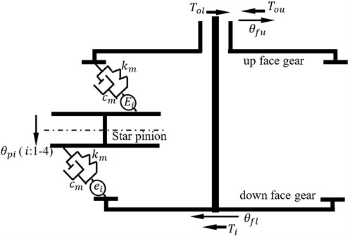
According to design requirements of helicopter main gear boxes, differential face gear trains are divided into two types. One is up-input version, namely, the first version, the other is down-input version, meaning, the second version. The sketches of two version differential face gear trains are shown in Fig. 1.
As illustrated in Fig. 1, in the first version differential face gear train, the input face gear is the up face gear, and the output face gear is the down face gear. While, in the second version differential face gear train, the input face gear is the down face gear, and the output face gear is the up face gear. Thus, the first version differential face gear train can be designed in main gear boxes associated with less depth, versus the second version.
Fig. 1Two version differential face gear trains
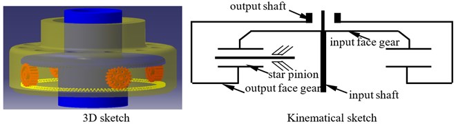
a) The first version
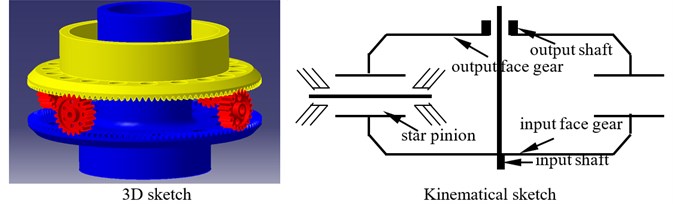
b) The second version
2.2. Star pinion geometry phase calculation solution constructed
The star pinion geometry phase adjustment solution means getting the same geometry phases of star pinions at input stages by adjusting star pinion assembly positions. Thus, the star pinion geometry phase calculation solution is the base of the proposed star pinion geometry phase adjustment solution.
A face gear tooth is a kind of gear teeth associated with variable tooth thicknesses, and can be considered as a sequence in which modified involute gears are superimposed along its face width. Meanwhile, based on the contact viewpoints of face gear drives, face gear drives can be equivalent to involute gear drives. The evolution process of equivalent face gear drives is shown in Fig. 2.
As shown in Fig. 2, the contact relationship between face gears and pinions can be equivalent as that of between involute gears and pinions. Thus, star pinion geometry phases of differential face gear trains can be assumed as shown in Fig. 3.
Fig. 2An evolution process of equivalent face gear teeth
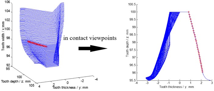
Fig. 3A sketch of star pinion phases assumed
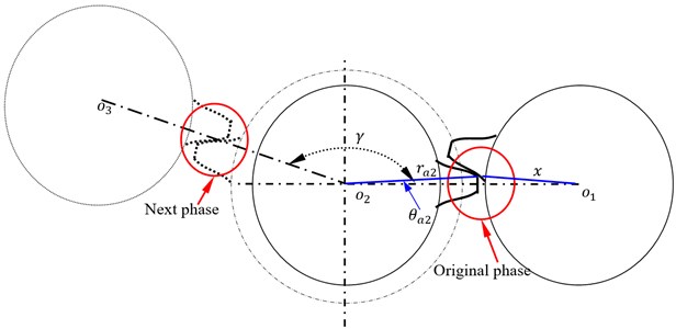
In Fig. 3, is defined as star pinion position angles, and is determined by design requirements of differential face gear trains, symbol can be derived by:
where is an addendum radius of star pinions, and symbol can be calculated by:
where is a tooth number of star pinions, is a pressure angle of reference cycle of star pinions, is an addendum pressure angle of star pinions.
According to the relationship between symbol and the dedendum radius of driving face gear equivalent gears , original phases can be determined in a piecewise form as:
where is a dedendum pressure angle of driving face gears, and can be expressed as:
where is a base cycle radius of driving face gear equivalent gears.
Next phase deduced is similar with that of original phases, and can be derived in a piecewise form as:
where is an addendum pressure angle of driven face gears, and can be written in:
where is a base cycle radius of driven face gear equivalent gears, and can be given in a piecewise form as:
where is a dedendum radius of driven face gear equivalent gears, symbol “round” means taking remainders, and symbol can be obtained in a piecewise form as:
where symbol “int” means integers, is a dedendum pressure angle of star pinions.
2.3. Dynamic model
In engineering designs of coaxial helicopter main gear boxes associated with differential face gear trains, if traditional adjustment solutions of differential face gear trains, namely, tooth number adjustments, are employed, drive ratios of differential face gear trains would be changed, which would affect the total design of helicopter main gear boxes. While, the proposed star pinion geometry phase adjustment solution, meaning, assembly position adjustments of star pinions, would not change drive ratios and be implemented easily.
In order to evaluate influences of the proposed star pinion geometry phase adjustments on dynamic load sharing behaviors of two version differential face gear trains, a six DOF torsion dynamic model associated with four star pinions, which can reflect two versions by inputting base dynamic parameter adjustments, is formulated, as shown in Fig. 4.
As shown in Fig. 4, the total powers are transmitted to the input face gear, namely, the up face gear in the first version or the down face gear in the second version, as shown in Fig. 1, by the input shaft. Due to differential face gear trains, one part of powers on input face gear is consumed by external loads directly, and the rest part of powers is shared by star pinions through input face gear pairs. Then, the rest part of powers is collected to the output face gear, meaning, the down face gear in the first version or the up face gear in the second version, as shown in Fig. 1, by output facer gear pairs. Finally, the rest part of powers is used up by other out loads. In the power transmission procession of differential face gear trains, dynamic loads on star pinions determined by differential face gear train dynamics are different, which would affect differential face gear train performance greatly, due to star pinion geometry phases, etc. Thus, in order to assess star pinion dynamic load sharing behaviors, introducing star pinion geometry phases into static transmission errors and according to the dynamic model, as given in Fig. 4, the mathematic equations of the six DOF torsion dynamic model can be derived by:
where subscript and express a star pinion and a face gear respectively, subscript and are a down face gear and a up face gear respectively, is a torsion degree of freedom, is a moment of inertia, is a input torsion, and are output torsions on the down and up face gears respectively, “.” is first derivative, “.." is second derivative, is a base circle radius, is mesh stiffness, is mesh damping, and are STE of the down and up face gear drives, respectively.
In addition, the input or output stage dynamic load sharing coefficient can be defined as:
and the total dynamic load sharing coefficient can be determined by:
where is an amplitude versus frequencies, is a number of frequencies, subscript and express input and output dynamic load sharing coefficients, respectively.
Fig. 4A torsion dynamic model
3. Simulations and effect predictions
3.1. Simulations
In order to evaluate dynamic load sharing behaviors of two version differential face gear trains without star pinion geometry phase adjustments, namely, star pinion equispaced, as shown in Fig. 5, geometric parameters, operating conditions and material characteristics of an example case of two versions associated with four star pinions are given in Table 1.
Fig. 5A sketch of star pinion equispaced
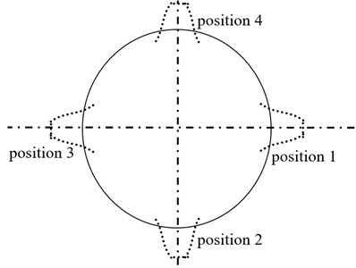
In the case of Fig. 5, according to the parameters listed in Table 1 and the proposed star pinion geometry phase calculation solutions, the star pinion geometry phases of the example case of two versions are calculated as given in Table 2.
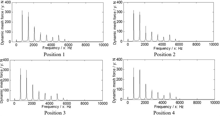
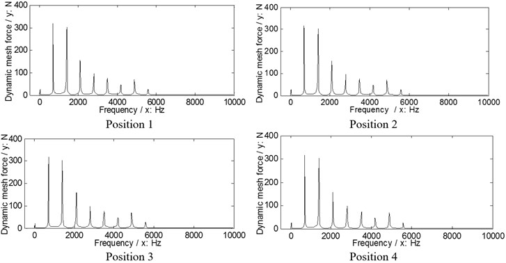
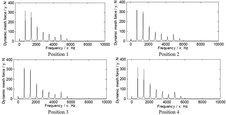
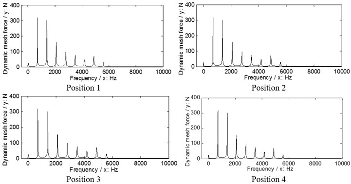
According to Eq. (9), the dynamic load sharing behaviors of the example case of two version differential face gear trains are simulated as shown in Figs. 6, 7.
Table 1Parameters of the example case
Names | Values | Units | |
Geometric parameters | Modulus | 4 | mm |
Pressure angle | 25 | ° | |
Tooth number of pinions | 25 | – | |
Tooth number of face gears | 105 | – | |
Addendum coefficient | 1 | – | |
Clearance coefficient | 0.25 | – | |
Operating conditions | Power | 80 | kW |
Input rotation speed | 400 | r/min | |
Material characteristics | Modulus of elasticity | 210000 | MPa |
Poisson ratio | 0.3 | – |
Fig. 6The dynamic load sharing behaviors of the first version simulated
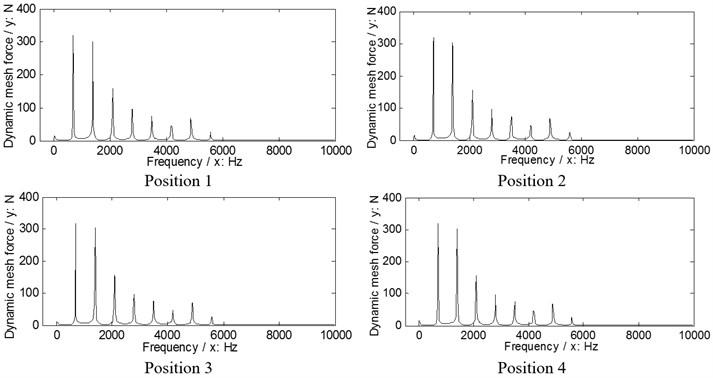
a) Input stages
b) Output stages
According to the results in Figs. 6, 7 and Eq. (10) as well as Eq. (11), the dynamic load sharing coefficients of the example case of two versions without star pinion geometry phase adjustments can be calculated as listed in Table 3.
According to the results as listed in Table 3, the total dynamic load sharing coefficient of the second version is better than that of the first version, but the dynamic load sharing behaviors of two versions are not well due to the results beyond the normal range suggested by design experiences, namely, 1.02 to 1.06.
Table 2Star pinion geometry phases of the example case of two versions
Types | Position 1 | Position 2 | Position 3 | Position 4 | Unit |
Output stages of the first and second versions | 0.0045 | 0.0188 | 0.0155 | 0.0188 | rad |
Input stages of the first and second versions | 0.002 | 0.0052 | 0.0085 | 0.0052 |
Table 3Dynamic load sharing coefficients without star pinion geometry phase adjustments
The first version | The second version | |
Coefficient of input stages | 1.23 | 1.14 |
Coefficient of output stages | 1.07 | 1.04 |
Total coefficient | 1.15 | 1.09 |
Fig. 7The dynamic load sharing behaviors of the second version simulated
a) Input stages
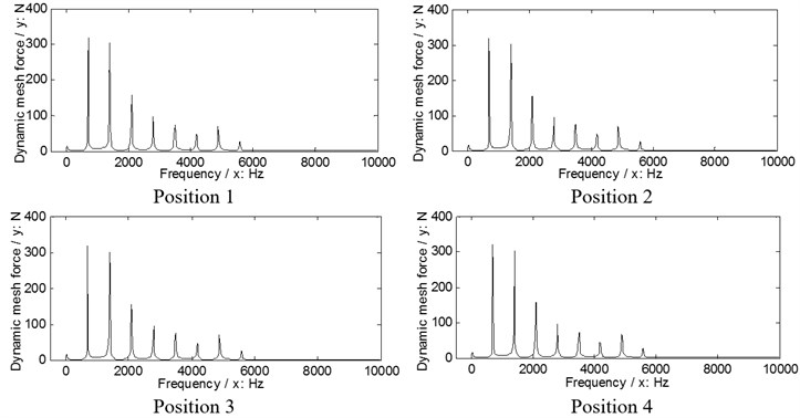
b) Output stages
3.2. Effect predictions
In order to assess effects of the proposed star pinion geometry phase adjustments on dynamic load sharing behaviors of two versions, the star pinion positions adjusted of the example case, which would cause the same geometry phases of star pinions at input stages, is calculated as shown in Fig. 8, and the star pinion geometry phases of the example case associated with the adjustments are obtained as listed in Table 4.
Fig. 8A sketch of star pinion assembly position adjustments
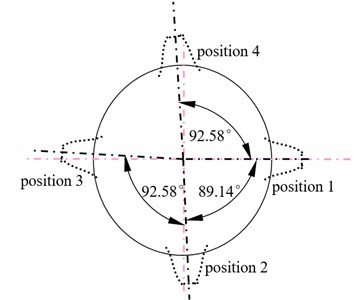
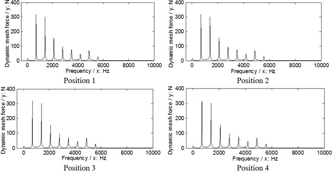
Fig. 9The dynamic load sharing behaviors of the first version associated with the proposed adjustments
a) Input stages
b) Output stages
Fig. 10The dynamic load sharing behaviors of the second version associated with the proposed adjustments
a) Input stages
b) Output stages
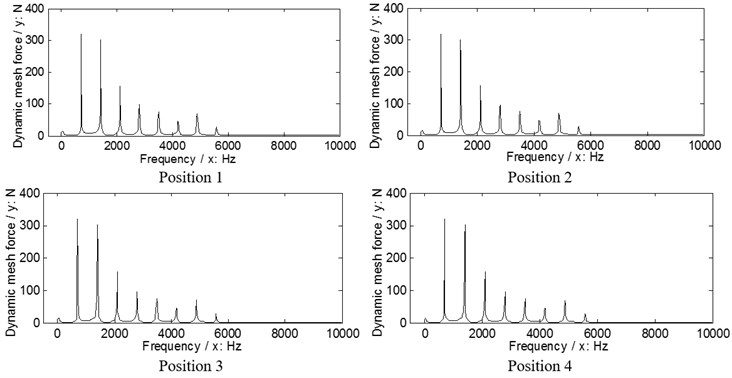
According to Eq. (9), the dynamic load sharing behaviors of the example case of two versions associated with the proposed star pinion geometry phase adjustments are simulated as shown in Figs. 9, 10.
According to the results in Figs. 9. 10, the dynamic load sharing coefficients of the example case of two versions associated with star pinion geometry phase adjustments can be calculated as listed in Table 5.
Table 4Geometry phases of the example case of two versions associated with the proposed adjustments
Types | Position 1 | Position 2 | Position 3 | Position 4 | Unit |
Output stages of the first and second versions | 0.0045 | 0.022 | 0.022 | 0.022 | rad |
Input stages of the first and second versions | 0.002 | 0.002 | 0.002 | 0.002 |
Table 5Dynamic load sharing coefficients associated with star pinion geometry phase adjustments
The first version | The second version | |
Coefficient of input stages | 1.032 | 1.03 |
Coefficient of output stages | 1.019 | 1.02 |
Total coefficient | 1.026 | 1.025 |
The difference between before and after star pinion geometry phase adjustments can be defined as:
where is a total coefficient without the proposed star pinion geometry phase adjustment, is a total coefficient with the proposed star pinion geometry phase adjustment.
According to the results as listed in Table 5 and Table 3, and Eq. (12), the differences can be calculated as listed in Table 6.
According to Table 6, the effects of star pinion geometry phase adjustments on dynamic load sharing behaviors are significant, and the improved effect of the first version is better than that of the second version.
Table 6The differences between before and after adjustments
The first version | The second version |
10.8 % | 5.96 % |
4. Conclusions
In the study, three conclusions can be extracted as follows:
1) A star pinion geometry phase adjustment solution, which would not change drive ratios of differential face gear trains versus traditional parameter adjustment solutions, is proposed, and a star pinion geometry phase calculation solution is constructed.
2) Dynamic load sharing behaviors of the first version differential face gear train is worse than those of the second version under the condition of star pinion equispaced, namely, without the proposed star pinion geometry phase adjustment.
3) The effects of the proposed star pinion geometry phase adjustment solution on dynamic load sharing behaviors of two version differential face gear trains are significant, and the improved effects of the first version associated with the proposed adjustment solution is better than that of the second version.
These contributions would be helpful to improve dynamic load sharing designs of differential face gear trains in the future.
References
-
Litvin F., Bossler R., Chen Y.-J., Zhang Y., Wang J.-C. Design and geometry of face-gear drives. Journal of Mechanical Design, Vol. 114, Issue 4, 1992, p. 642-647.
-
Litvin F. L., Fuentes A., Zanzi C., Pontiggia M. Design, generation, and stress analysis of two versions of geometry of face-gear drives. Mechanism and Machine Theory, Vol. 37, Issue 10, 2002, p. 1179-1211.
-
Litvin F. L., Gonzalez-Perez I., Fuentes A., Vecchiato D., Hansen B. D., Binney D. Design, generation and stress analysis of face-gear drive with helical pinion. Computer Methods in Applied Mechanics and Engineering, Vol. 194, Issue 36, 2005, p. 3870-3901.
-
Litvin F. L., Fuentes A., Howkins M. Design, generation and TCA of new type of asymmetric face-gear drive with modified geometry. Computer Methods in Applied Mechanics and Engineering, Vol. 190, Issue 43, 2001, p. 5837-5865.
-
Litvin F. L., Egelja A., Tan J., Chen D., Heath G. Handbook on Face Gear Drives with a Spur Involute Pinion. DTIC Document, 2000.
-
Litvin F., Bossler R., Chen Y.-J., Lewicki D., Heath G., Wang J.-C. Application of face-gear drives in helicopter transmissions. Journal of Mechanical Design, Vol. 116, Issue 3, 1994, p. 672-676.
-
Jin G. H., Zhu R. P., Bao H. Y. Nonlinear dynamical characteristics of face gear transmission system. Journal of Central South University (Science and Technology), Vol. 5, Issue 41, 2010, p. 1807-1813, (in Chinese).
-
Li X. Z., Zhu R. P. Z., Li Z. M. Q., Jin G. H. Influence of frictional coefficient on vibration characteristc of face gear transmission system. Journal of Vibration Engineering, Vol. 27, Issue 4, 2014, p. 584-588, (in Chinese).
-
Yang Z., Wang S.-M., Fan Y.-S., Liu H.-X. Bifurcation charactristics of face-gear transmission system. Journal of Harbin Institute of Technology, Vol. 3, Issue 43, 2011, p. 107-110, (in Chinese).
-
Yang Z., Wang S.-M., Fan Y.-S., Liu H.-X. Vibration characteristics of face-gear transmission system with parametric excitation. Journal of Chongqing University, Vol. 35, Issue 1, 2011, p. 26-35, (in Chinese).
-
Hu Z. H., Tang J. Y., Chen S. Y., Lei D. C. Effect of mesh stiffness on the dynamic response of face gear transmission system. Journal of Mechanical Design, Vol. 135, Issue 7, 2013, p. 1-7.
-
Wang R., Zhao N., Tao L., Jia Q., Guo H. Floating shaft load sharing method for face gear split torque transmission system. Research Journal of Applied Sciences, Engineering and Technology, Vol. 5, Issue 12, 2013, p. 3386-3392.
-
Zhang L., Ru-peng Z., Min-qing L. Z. Research on natural frequency of torsional vibration of torque-split face gear transmission system. Jiangsu Machine Building and Automation, Vol. 41, Issue 5, 2012, p. 21-24, (in Chinese).
-
Seager D. L. Conditions for the neutralization of excitation by the teeth in epicyclic gearing. Journal of Mechanical Engineering Science, Vol. 17, 1975, p. 293-298.
-
Kahraman A. Planetary gear train dynamics. Journal of Mechanical Design, Vol. 116, 1994, p. 713-720.
-
Lin J., Parker R. G. Analytical characterization of unique properties of planetary gear free vibration. Journal of Vibration and Acoustics, Vol. 121, 1999, p. 316-321.
About this article

The authors are grateful for the financial support provided by the National Natural Science Foundation of China under No. 51105194 and No. 51375226, and the Fundamental Research Funds for the Central Universities under No. NS2015049.
In addition, the authors declare that there is no conflict of interests regarding the publication of this article.
