Abstract
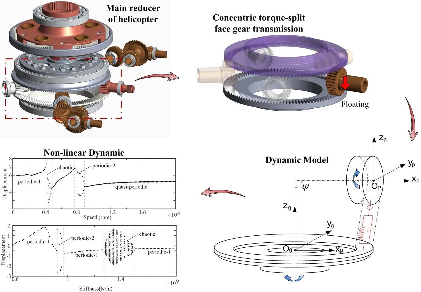
The face gear pair has been applied in the main reducer of helicopter. Considering the nonlinear backlash, time-varying meshing stiffness and static transmission error, a six degree-of-freedom lumped parameter dynamic model coupling with flexional, torsional and axial motion of the face gear pair for helicopter is developed. This model takes the floating of the pinion as the boundary condition. The nonlinear dynamic characteristics of the face gear pair are analyzed by the help of bifurcation diagram. The effects of rotational speed and supporting stiffness of the pinion on the dynamic responses of the face gear pair are studied in detail by using numerical method. Numerical examples reveal several dynamic evolution mechanisms and motion states including periodic-1, periodic-2, chaotic and quasi-periodic motions. Some research results are helpful for vibration control and dynamic design of the face gear pair for helicopter.
1. Introduction
The face gear drive plays more and more important role in the power transmission system of helicopter for its ability of torque-split and insensitivity to misalignment error [1-3]. The transmission system of helicopter has the characteristics of high speed, heavy load and complex operating ambient, which make gears prone to damage due to fierce vibration. Therefore, it is imperative to develop accurate and reliable dynamic models of the face gear pair to investigate the failure mechanisms. Actually, research on the dynamic behaviors of gear transmission system has been one of the most important aspect of power transmission design. The study of dynamic response is the basis of fatigue life prediction and health monitoring of gear transmission system.
The face gear drive has been applied on the helicopter transmission since the 1990s. Litvin et al. [4, 5] described the torque-split face gear transmission design in the first place. And a series of experimental and theoretical studies [6-10] shown that the application of face gear in the helicopter transmission was feasible. In Ref. [11], Chen et al. investigated the nonlinear dynamic responses of face gear drive system by a 6-DOF dynamic model considering backlash, time-varying meshing stiffness, time-varying arm of meshing force and effect of modification. Hu et al. [12] presented a 14-DOF dynamic model of face geared rotor system. Effects of backlash and load on the dynamic responses were investigated through numerical simulations.
Limited works have been addressed to the dynamic behaviors of the face gear pair considering its application on the transmission system of helicopter. The operating environment of helicopter is complicated and the transmission system often bears alternating loads due to the factors such as backlash, time-varying meshing stiffness and external excitation which will cause gear faults. Accordingly, it is imperative to reveal the intrinsic relations between these factors and the dynamic characteristics of the face gear pair for helicopter.
2. Nonlinear dynamic model of the face gear pair
The face gear pair investigated in the present study is mainly composed of supporting shafts, spur gear, face gear, bearings and other auxiliary components. A translational-torsional-axial coupled 6-DOF dynamic model of this type of mechanical transmission system is established. The gear bodies are regarded as rigid disks. As is shown in Fig. 1, the tooth meshes are modeled as a nonlinear spring-damper element, and the bearings are also simplified as linear spring-damper elements, denotes half of the total backlash, and are the time varing meshing stiffness and viscus mesh damping coefficient respectively, represents the time-varying static transmission error.
Fig. 1The dynamic model of the face gear pair
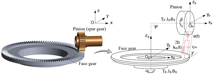
For analytical convenience, by translating the angular displacement to the LOA direction, the generalized displacement vector can be expressed as:
where , is the base circle radius of the pinion, is the pitch radius of the face gear.
Usually, the nonlinear gear backlash adopts the following expression:
The time-varying meshing force can be derived as:
where is the backlash function, the superscript “” is the differentiation of time .
The equations of motion for the translational-torsional-axial coupled 6-DOF dynamic model shown in Fig. 1 can be derived by Newton’s second law of motion as:
where is the mass of gear , is the mass moment of inertia of gear , and are the average supporting stiffness and bearing damping of gear respectively along direction (, ).
The non-demensional time is defined by , where is the meshing period of gear teeth. By defining a displacement nominal scale of 1 μm, the non-demensional displacements, velocities and accelerations can be expressed as:
Imposing the expressions above, the non-demensional form of the governing equations of motion of the translational-torsional-axial coupled 6-DOF dynamic model can be expressed as:
3. Calculation of the time-varying meshing stiffness when the pinion floats
The concentric torque-split face gear transmission is shown in Fig. 2, it was first proposed by the Enhanced Rotorcraft Drive System Program (ERDS), which was cooperated by the US Army and Boeing company. The pinion drives in between the two face gears and the input torque is distributed to the upper and lower face gears. The pinion is designed to float, so that the torque can be divided evenly to the two face gears [1, 2]. The stiffness of the upper and lower power transmission paths is asymmetric, and the load distributed to the upper face gear is higher [3], so the pinion floats downward. This results in non-standard meshing between the pinion and the lower face gear, and the meshing stiffness will change. The meshing stiffness is an important excitation of the gear transmission system, and it is necessary to study the nonlinear vibration characteristics of the lower mesh of pinion under the even load sharing condition.
Under the even load sharing condition, the pinion floats downward, and the time-varying meshing stiffness cannot be calculated according to the method proposed in reference [13]. Moreover, the tooth surface of the face gear is complex, and the tooth thickness varies along the tooth width direction. Thus, the analytical solution of the time-varying meshing stiffness of the face gear transmission is hard to obtain. In this section, the finite element method is used to calculate the time-varying meshing stiffness of the face gear transmission when the pinion floats.
The basic design parameters of the face gear pair for stiffness calculations is shown in Table 1. After the meshing stiffness of all the meshing positions are calculated, the meshing stiffness changes along with time points is shown in Fig. 3.
Fig. 2The concentric torque split face gear transmission
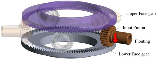
Fig. 3Time-varying meshing stiffness when the pinion floats
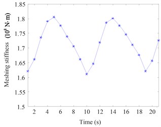
Table 1Basic design parameters of the face gear pair for stiffness calculations
Parameter | Pinion | Face gear |
Tooth number | 21 | 142 |
Modulus / (mm) | 1.95 | 1.95 |
Pressure angle / (°) | 25 | 25 |
Tooth with / (mm) | 27 | 25 |
Inner diameter / (mm) | – | 255 |
Outer diameter / (mm) | – | 305 |
Backlash / (μm) | 25 | 25 |
4. Nonlinear dynamic responses
4.1. Effect of rotational speed of pinion
The rotational speed of pinion is one of the main parameters that affect the dynamic responses of the face gear pair. The bifurcation characteristic of the face gear pair in dimensionless displacement with respect to the rotational speed of pinion is illustrated in Fig. 4. From this figure, four kinds of motions are presented as the rotational speed of pinion changes: periodic-1 motion, chaotic motion, periodic-2 motion and quasi-periodic motion.
Fig. 4Bifurcation diagram of the face gear pair using speed as bifurcation parameter
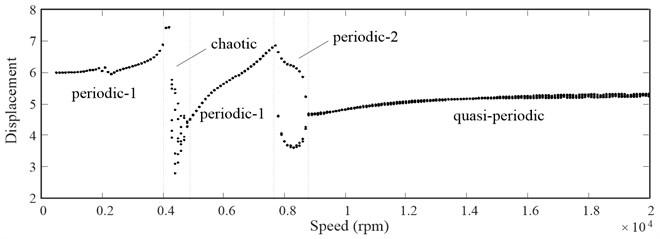
When the rotational speed is less than 4000 rpm, the system dynamic response is periodic-1 motion. The phase plane diagram is just a closed circle, the Poincaré map only has one single point, the time domain spectrum shows a sine curve, and the FFT spectrum also just has one-peak amplitude. The results indicate that the system is in periodic-1 motion.
When the rotational speed increases to 4000 rpm but less than 4800 rpm, the system dynamic response changes from periodic-1 motion to chaotic motion, which can be seen clearly in Fig. 4. In this region, the bifurcation diagram has numerous points. The Phase plane diagram shows that the curve is full of the space, there are many discrete points in the Poincaré map, the time domain spectrum shows a non-periodic motion, and the FFT spectrum also has multi-peak amplitude. The above results show that the system is in chaotic motion.
When the rotational speed changes from 4800 rpm to 7600 rpm, the system dynamic responses back to periodic-1 motion again, which can be seen clearly in Fig. 4. The rated rotational speed of the pinion in the transmission system of the helicopter is 6409.86 rpm. From the dynamic responses analysis above we know that the system is in periodic-1 motion. When the rotational speed increases from 7600 rpm to 8800 rpm, the system dynamic response is a periodic-2 motion. There are two points in the Poincaré map, two closed circles in the phase plane diagram, and numerous excitation frequencies in the FFT spectrum. Also, the time domain spectrum appears periodic.
When the rotational speed is higher than 8800 rpm, the system dynamic response leaves periodic-2 and turns to quasi-periodic motion for a long range, which can be revealed exactly from Fig. 4. The phase plane diagram shows a curve belt with certain width, the Poincaré map has a small region that formed by numerous points, and the time domain spectrum shows a periodic motion. All these results means that the system is in quasi-periodic motion.
4.2. Effect of supporting stiffness
The supporting stiffness of pinion is also one of the main parameters that affects the dynamic responses of the face gear pair. The bifurcation characteristic of the face gear pair in dimensionless displacement with respect to the supporting stiffness of pinion is illustrated in Fig. 5 when the rotational speed is 3000 rpm. There are three kinds of motions, namely periodic-1 motion, periodic-2 motion and chaotic motion, as can be seen from the bifurcation diagram.
Fig. 5Bifurcation diagram of the face gear pair using pinion’s supporting stiffness as bifurcation parameter
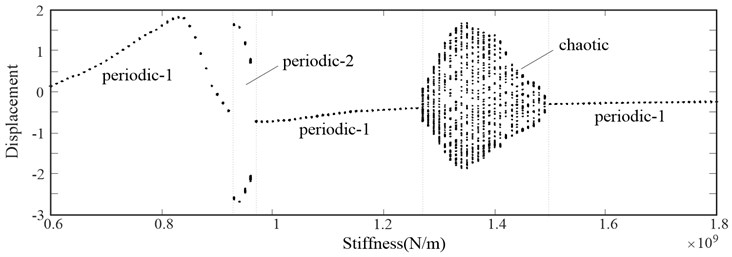
The Bifurcation diagram depicted in Fig. 5 shows that when the supporting stiffness of pinion is less than 9.3×10⁸ N/m, the system dynamic response is a periodic-1 motion. With the increasing of the supporting stiffness of the pinion, the system turns to periodic-2 motion which remains from 9.3×10⁸ N/m to 9.6×10⁸ N/m. From 9.6×10⁸ N/m to 1.27×10⁹ N/m, the system leaves periodic-2 and returns to periodic-1 again. When the supporting stiffness of pinion is increased to 1.27×10⁹ N/m, the system dynamic response is changed from periodic-1 motion to chaotic motion, and it is continued until 1.5×10⁹ N/m. When the supporting stiffness of pinion is greater than 1.5×10⁹ N/m, the system leaves chaotic and return to periodic-1 again for a long range of the pinion stiffness until 1.8×10⁹ N/m.
From the dynamic responses of the face gear pair mentioned above, it can be concluded that the support stiffness of the pinion has an important influence on the motion of the system. When the support stiffness of pinon is less than 8.3×10⁸ N/m, the vibration displacement raises to a relatively large value, and the large amplitude part of the system concentrated in high frequency. While as the support stiffness of the pinion increases, the vibration displacement inclines to decrease, the large amplitude part moves to low frequency.
5. Conclusions
The face gear pair is mainly used in the transmission system of helicopter which requires low vibration and high reliability. The reliable dynamic model of the face gear drive is the basis of reducing vibration and improving reliability for the face gear pair of the helicopter. Considering the backlash and the time-varying meshing stiffness when the pinion floats, this paper presents a dynamic model of the face gear pair. The dynamic responses are obtained through Runge-Kutta method. The effects of rotational speed and supporting stiffness of pinion on the nonlinear dynamic responses of the face gear pair are analyzed with numerical method.
As mentioned in the numerical examples above, with the changing of the rotational speed and supporting stiffness of pinion, the dynamic responses of system contained four motions: periodic-1 motion, periodic-2 motion, chaotic motion and quasi-periodic motion. It shows that the changes of rotational speed or supporting stiffness of pinion lead to complex dynamic responses of the system. Especially when the system is in the state of chaotic motion, the interaction between gears becomes complex and the gear vibration becomes fierce, which lead to failure and instability of the face gear pair. To reduce the vibration and increase stability, it is necessary to match the rotational speed of pinion with the reduction ratio, and to select an appropriate supporting stiffness of the pinion based on the optimal design method for the face gear pair.
On the whole, the works in this paper not only present us a method to study the nonlinear dynamic characteristic of the face gear pair, but also provide ideas for vibration control of the main reducer of the helicopter in the future.
References
-
Heath G. F., Filler R. R., Tan J. Development of Face Gear Technology for Industrial and Aerospace Power Transmission. NASA Report, NASA/CR-2002-211320, 2002.
-
Filler R. R., Heath G. F., Slaughter S. C., et al. Torque splitting by a concentric face gear transmission. American Helicopter Society 58th Annual Forum, Montreal, Canada, 2002.
-
Ning Zhao, Wang Li, Hu Tao, et al. Concentric torque-split face gear transmission with flexible face gear. Mathematical Problems in Engineering, Vol. 2018, 2018, p. 6568519.
-
Litvin F. L., Heath G., Lewicki D. J., et al. Face-Gear Drives: Design, Analysis and Testing for Helicopter Transmission Applications. AGMA Paper 92FTM2, 1992.
-
Litvin F. L., Wang J. C., Bossler R. B., et al. Application of face-gear drives in helicopter transmissions. Journal of Mechanical Design, Vol. 116, Issue 3, 1994, p. 672-676.
-
Litvin F. L., Egelja A., Tan J., et al. Handbook on Face Gear Drives with a Spur Involute Pinion. NASA Final Contractor Report CR-209909, 2000.
-
Lewicki D. G., Heath G. F., Filler R. R., et al. RDS-21 Face-Gear Surface Durability Tests. NASA Report, NASA/TM-2007-214970, 2007.
-
Tsuji I., Gunbara H., Kawasaki K., et al. Machining and running test of high-performance face gear set. International Design Engineering Technical Conferences and Computers and Information in Engineering Conference, 2011, p. 73-80.
-
Saribay Z. B., Bill R. C. Design analysis of pericyclic mechanical transmission system. Mechanism and Machine Theory, Vol. 61, 2013, p. 102-122.
-
Guang Hu, Ru Peng Z., He Yun B. Nonlinear dynamical characteristics of the face gear transmission system. Journal of Central South University, Vol. 41, Issue 5, 2010, p. 1807-1813, (in Chinese).
-
Chen S., Tang J., Chen W., et al. Nonlinear dynamic characteristic of a face gear drive with effect of modification. Meccanica, Vol. 49, Issue 5, 2014, p. 1023-1037.
-
Hu Z., Tang J., Chen S., et al. Coupled translation-rotation vibration and dynamic analysis of face geared rotor system. Journal of Sound and Vibration, Vol. 351, 2015, p. 282-298.
-
Hu Z., Tang J., Chen S., Lei D. Effect of mesh stiffness on the dynamic response of the face gear transmission system. Journal of Mechanical Design, Vol. 135, Issue 7, 2013, p. 071005.
About this article

