Abstract
The vibration model of four-stage main transmission system in helicopter was established through lumped mass method. In the model, many factors, including time-varying meshing stiffness and torsional stiffness of gear shaft were considered. The differential equation of the system was solved via Fourier method, and the influence of the torsional stiffness of shafts on the first five orders of the system’s natural frequency was studied. Some theoretical results were summarized as guidelines for further research and design of four-stage deceleration helicopter at last.
1. Introduction
The four-stage main transmission system has the ability to carry heavy load, and it has an essential effect in dynamic behavior in three-engine helicopters. Predicting natural characteristics might protect the whole system from further failure and damage. However, its structure is extremely complicated, it has multiple branches of input and output, along with long transmission chain which includes numerous gears and accessories [1]. In addition, mutual coupling exists in each branch and whole system, and the system is affected by several dynamic factors like time-varying meshing stiffness, clearance and synthetic transmission error. Furthermore, the input speed of engine is greatly high which has huge effect on the vibration of the system. Therefore, it is urgent and meaningful to analyze and study its vibration characteristics.
For the vibration characteristics of helicopter main transmission system, scholars study the modal vibration of complex multi-shaft system of a variety of gear pair meshing [2], and analyze the influence of meshing stiffness, installation angle, spiral angle and bearing stiffness on the natural characteristics of the system [3, 4].
On the other hand, in terms of the planetary gear chain of main transmission system, the effects of torque on dynamic behavior in torsional model are analyzed [5, 6]. Other studies of planetary gear dynamics include mesh stiffness variation and load-sharing [7], influence of free vibration [8, 9], and tooth crack detection [10].
In conclusion, most studies are limited in planetary chain system or the components of helicopter’s main reducer, few of them involve the overall components of main transmission system, which has long chain and multiple DOF. Besides, it is presently still difficult to analyze the impact of torsional stiffness of shaft on the vibration characteristics. Therefore, in the paper, the influence of the changes of torsional stiffness on various orders of natural frequency was explored, and theoretical support was provided for the design of the helicopter.
2. Dynamic modeling of the system
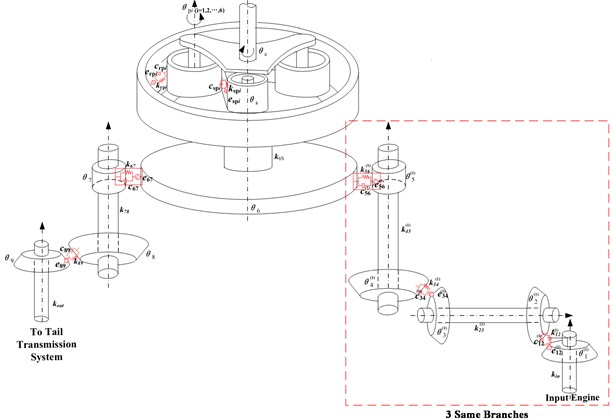
The dynamic model of four-stage deceleration helicopter’s transmission system is shown in Fig. 1. In the picture, the system has three same input branches, namely branch ( 1, 2, 3). Each branch has 5 gears. , , , , , , , , , and are rotational DOF of gear system in each stage deceleration.
, , , , and are torsional stiffness of shafts connecting each gear pair; , , , and are meshing damping of each gear pair; , , , and are meshing stiffness of each gear pair. The flexibility between the shafts and transverse DOF are not taken into account due to its weak influence on natural frequency.
Fig. 1Model of three-engine helicopter transmission system
The differential equation of the trial model system can be deduced through Newton’s law, as shown below:
where is denoted as the output torque of engine ( 1, 2, 3); and are the output torque of tail branch and planet carrier. and are dynamic meshing and damping forces of each gear pair.
In addition, after the decomposition and recombination of Eq. (1), it can be expressed with following matrix-vector form:
Here [], [], [] are the mass matrix, damping matrix and stiffness matrix of the governing equation, and all matrices are in 27 dimension; matrix [] is external excitation.
3. System natural characteristics analysis
A set of basic parameters are extracted from a geared system, listed in Table 1. By setting the value of damping item and external excitation item in Eq. (2) to be zero, the vibration differential equation of the system under free condition can be obtained.
Table 1Gear parameters
Tooth number | Module | Face width (mm) | Initial phase of meshing stiffness (°) | |
Gear 1 (First stage) | 30 | 4.5 | 40 | 0 |
Gear 2 (First stage) | 85 | 4.5 | 40 | 0 |
Gear 3 (Second stage) | 40 | 5 | 60 | 20 |
Gear 4 (Second stage) | 90 | 5 | 60 | 20 |
Gear 5 (Third stage) | 25 | 4.75 | 40 | 30 |
Gear 6 (Third stage) | 142 | 4.75 | 40 | 30 |
Gear 7 (Tail branch) | 40 | 5 | 35 | 0 |
Gear 8 (Tail branch) | 60 | 5 | 35 | 0 |
Gear 9 (Tail branch) | 70 | 5 | 40 | 20 |
Gear 10 (Sun gear in fourth stage) | 68 | 5 | 40 | 20 |
Gear 11 (Planet gear in fourth stage) | 37 | 5 | 40 | , , , , , |
The helicopter has multiple stage deceleration shaft system. is torsional stiffness of each gear pair. The change of the value of torsional stiffness means the change of stiffness matrix, affecting natural frequency accordingly. In the paper, torsional stiffness of shafts was changed; the influence of change of torsional stiffness on the natural characteristics was explored; theoretical support was provided for the design of the helicopter shaft.
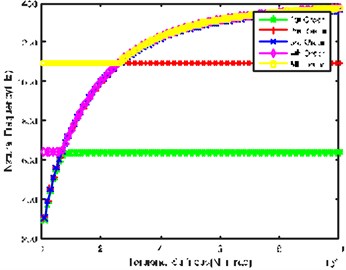
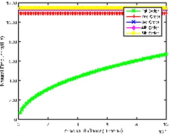
Fig. 2(a) indicates the impact of input shaft torsional stiffness on natural frequency. It shows that the values of natural frequency are close and at the low frequency regions when input shaft torsional stiffness is lower; acceleration of rotational speed tends to cause resonance, so the shaft is key shaft; in case of resonance, it has bigger impact on planet chain and tail transmission system. In addition, when torsional stiffness is greater than 8×10⁴N·m/rad, 1st order natural frequency remains 640 Hz, while natural frequency of the rest orders continues to increase; when torsional stiffness is greater than 2×10⁵ N·m/rad, 2nd order natural frequency remains 1100 Hz, while natural frequency of the rest orders gradually tends to be stable and at high frequency areas with the increase of torsional stiffness. Moreover, 3rd order natural frequency always increases with the increase of torsional stiffness, and doesn’t become gradually stable until torsional stiffness is higher.
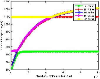
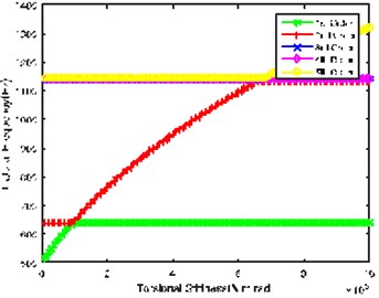
Fig. 2(b) is the impact of torsional stiffness of Gear 2 and Gear 3 connecting shaft on natural frequency, showing similar laws to Fig. 2(a). However, 2nd order natural frequency doesn’t remain stable at 1100 Hz until torsional stiffness is greater than 4.5×10⁵ N·m/rad. At the same time, the abrupt change point of the 5th order is delayed to 4.5×10⁵ N·m/rad.
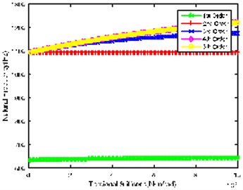
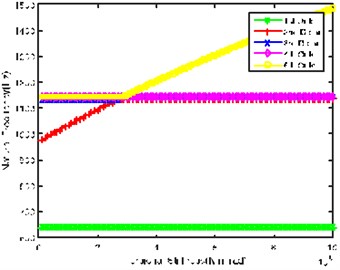
Fig. 2(c) shows the impact of torsional stiffness of Gear 4 and Gear 5 connecting shaft on natural frequency. It can be seen that the change of torsional stiffness slightly impacts first 4 orders natural frequency; 5th order natural frequency rises slightly with the increase of torsional stiffness, and is in the high frequency regions.
Fig. 2(d) shows the impact of torsional stiffness of sun gear input shaft on natural frequency. It can be seen that 1st order natural frequency almost shows linear increase, while natural frequency of other orders shows little change along with the increase of torsional stiffness; it crosses the low frequency regions when torsional stiffness is lower, so the shaft is also key shaft, and its torsional stiffness can’t be too low.
Fig. 2Impact of each shaft’s torsional stiffness on first five orders natural frequency
a)
b)
c)
d)
e)
f)
Fig. 2(e) and Fig. 2(f) respectively show the influence of Gear 7 and Gear 8 connecting shaft and tail branch’s output shaft on natural frequency. The values of natural frequency of all orders show similar trends and laws with the change of torsional stiffness. However, the stable point of 2nd order and the abrupt change point of 5th order natural frequency in Fig. 2(e) are 6.5×10⁵ N·m/rad, while the corresponding value in Fig. 2(f) is 3×10⁵ N m/rad, indicating that Gear 7 and Gear 8 connecting shaft is relatively important in tail transmission branch.
Through the comprehensive comparison of above figures, it can be found that system input shaft and sun gear input shaft have greater influence on 1st natural frequency; system input shaft and Gear 2 and Gear 3 connecting shaft have greater influence on 2nd natural frequency.
4. Conclusions
In this paper, a new dynamics model of four-stage helicopter transmission system is proposed and the analysis results enable us to draw the following conclusions:
System input shaft and the sun gear input shaft are the key shafts of the system due to their torsional stiffness affecting the low frequency region much more than other shafts.
Input shaft of the system as well as Gear 2 and Gear 3 connecting shafts greatly impact on the second order and third order natural frequency.
Gear 7 and Gear 8 connecting shaft is the most important shaft in tail transmission branch.
References
-
Bianchi A., Rossi S. Modeling and finite element analysis of a complex helicopter transmission including housing, shafts and gears. 1997.
-
Kahraman A., Zini D. M., Kienzle K. Dynamic analysis of a multi-shaft helical gear transmission by finite elements: model and experiment. ASME Journal of Vibrations and Acoustics, Vol. 126, Issue 3, 2004, p. 398-406.
-
Huang J., Zhang S., Zhang Y. The influences of system parameters on the natural characteristics of a parallel multi-shaft gear-rotor system. Machinery Design and Manufacture, Vol. 7, 2013, p. 15-17, (in Chinese).
-
Gu Z., Yang J. Analyses of torsional vibration characteristics for transmission system of helicopter. Journal of Nanjing University of Aeronautics and Astronautics, Vol. 29, Issue 6, 1997, p. 674-678, (in Chinese).
-
Ericson T. M., Parker R. G. Experimental measurement of the effects of torque on the dynamic behavior and system parameters of planetary gears. Mechanism and Machine Theory, Vol. 74, 2014, p. 370-389.
-
Saada A., Velex P. An extended model for the analysis of the dynamic behavior of planetary trains. Journal of Mechanical Design, Vol. 117, Issue 2A, 1995, p. 241-247.
-
Kasuba R., August R. Gear mesh stiffness and load sharing in planetary gearing. ASME Paper 84-DET-229, 1984.
-
Zhang L., Wang Y., Wu K., et al. Dynamic modeling and vibration characteristics of a two-stage closed-form planetary gear train. Mechanism and Machine Theory, Vol. 97, 2016, p. 12-28.
-
Noll M. C., Godfrey J. W., Schelenz R., et al. Analysis of time-domain signals of piezoelectric strain sensors on slow spinning planetary gearboxes. Mechanical Systems and Signal Processing, Vol. 72, 2016, p. 727-744.
-
Liang X., Zuo M. J., Hoseini M. R. Vibration signal modeling of a planetary gear set for tooth crack detection. Engineering Failure Analysis, Vol. 48, 2015, p. 185-200.
Cited by
About this article

This work is supported by the National Natural Science Foundation of PRC (Grant No. 51375226 and 51475226), China Scholarship Council (Grant No. 201606830019) and Postgraduate Research and Practice Innovation Program of Jiangsu Province.
