Abstract
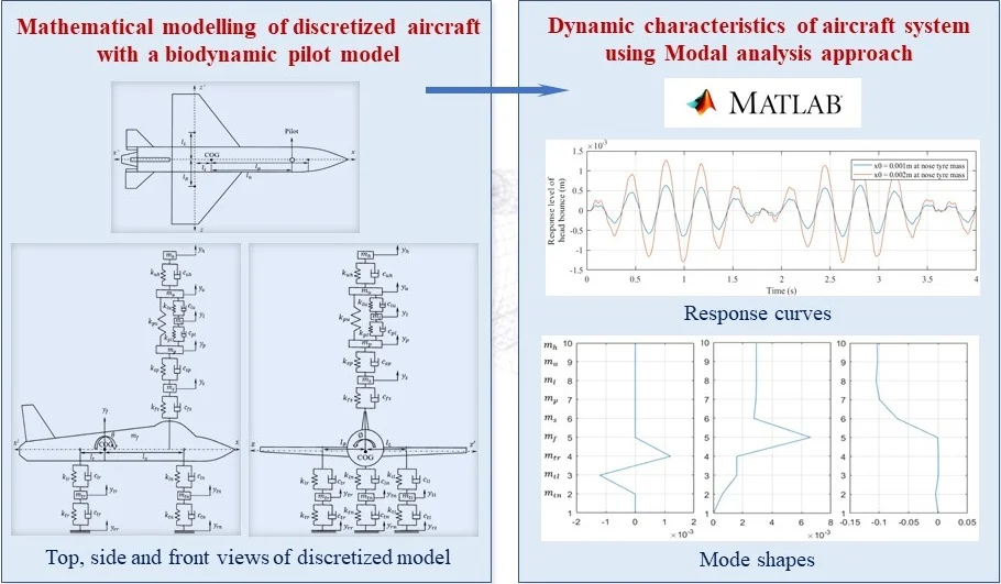
This work deals with the formulation of mathematical model for a discretized aircraft with combined seated biodynamic pilot model. The developed model provides scope for exploring the dynamic characteristics of the aircraft system and pilot under various runway operations and landing impacts. Modal analysis approach is used to obtain the free vibration characteristics of multi degrees-of-freedom system. The obtained results like natural frequencies, mode shapes and undamped response curves are reported.
Highlights
- Mathematical model of an eleven degree-of-freedom aircraft with integrated bio-dynamic pilot model is developed
- Modal analysis approach is used in the mathematical formulation and results are obtained in MatLab interface
- Free vibration responses and mode shapes of the aircraft system are obtained and reported
- The dynamic characteristics of a combined aircraft and biodynamic pilot system under various operating conditions like landing impact and runway maneuverings are studied
1. Introduction
Aviation is one of the most advancing industries offering faster connectivity of people and business across the modern world. It plays a major role in transportation of passengers, cargo and military operations. The advanced aircraft design demands multi-disciplinary engineering technologies including vibration, thermal, material science, electrical and electronical engineering. Aircrafts are subjected to various external excitations during the flight, landing and taxiing on rough runway surfaces. The induced vibration hinders pilot’s ability to control the aircraft leading to deterioration of comfort and safety levels of passengers and crew. With a prior knowledge of dynamic characteristics of the aircraft system, it is possible to develop and deploy vibration monitoring and mitigation techniques to avoid such critical issues.
Freymann [1] proposed a mathematical model of flexible aircraft to determine the realistic limits of aircraft operational capabilities on rough runway surfaces. The advantages of actively controlled landing gears in reducing the ground induced vibration is demonstrated. Sivakumar and Haran [2] developed and analyzed a detailed six degrees-of-freedom (DOF) full Fokker aircraft mathematical model describing an active landing gear tricycle system. It concludes the active landing gear increases ride comfort by reducing fuselage acceleration and vertical displacement. Gniady and Bauman [3] indicated the health issues faced by pilot due to induced vibration of lower frequency (0-20 Hz) and higher amplitude (0.2-1.2G). The resonant frequencies of whole-body vibration are reported. Liang and Chiang [4] carried out a thorough literature survey on lumped parameter models for seated human subjects exposed to vertical vibration. Based on the simulations, it is concluded that a four DOF human model proposed by Wan and Schimmels and a six DOF linear model developed from modifying the nonlinear model proposed by Muksian and Nash for cases such as pregnant subjects, matches with the experimental result. Abbas et al. [5] optimized the four DOF ‘Wan and Schimmels model’ using Genetic Algorithm (GA) optimization technique. Concluded that the optimized model is much closer to reality. Suggestion is made to extend the scope of work in including seated-human model in vehicle suspension systems and studying dynamic characteristics. Yazici and Sever [6] used Linear Matrix Inequalities (LMI) approach to design an observer based optimal state feedback controller for active vibration attenuation. An eleven DOF mathematical model of an aircraft with included biodynamic pilot model under runway disturbances during taxiing is considered for the study. Inman [7] explains a detailed approach of modal analysis for obtaining the dynamic characteristics of multi DOF systems. The ISO 2631-1 standard [8] explains the evaluation of human exposure to whole-body vibration and the effects of vibration on health, comfort and motion sickness of a human body.
In an attempt to suppress the unwanted vibrations, many researchers explored the dynamic behavior of aircraft system and developed valuable vibration mitigation techniques. Most of the research works in the field of aircraft dynamics are based on advanced simulation software. The scope for analytical discretization approach still persists. A predominant amount of work deals with the study of vibrational behavior of aircraft and biodynamic pilot models separately. A very few sources exist with the ideology of combined aircraft and pilot modelling which is a prime motivation for the present research work. An effort is made to develop a mathematical model of a six DOF discretized aircraft with an integrated five DOF biodynamic pilot model. This detailed eleven DOF aircraft model offers a forum to analyze dynamic characteristics of the system under runway and taxying excitations. Using modal analysis approach, free vibration analysis is carried out to retrieve and report the natural frequencies, mode shapes and time response curves for the proposed aircraft system.
2. Mathematical modelling of a discretized aircraft
A Fokker aircraft is discretized into a six degrees-of-freedom lumped mass model including vertical bouncing motions of fuselage and three tyres and angular motions of fuselage, both pitching and rolling. A five DOF seated bio-dynamic pilot model is incorporated in the aircraft model. The considered dynamics of the pilot model has vertical bouncing motions of seat suspension system, pelvis, lower torso, upper torso and head of pilot. Figs. 1-3 shows the schematic of a discretized eleven DOF aircraft system in different views including all the notations.
Fig. 1Top view of the aircraft
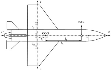
Fig. 2Right side view of the aircraft
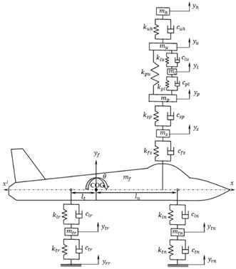
Fig. 3Front view of the aircraft
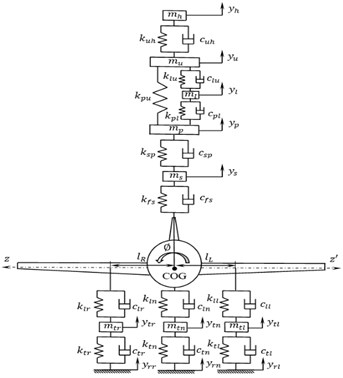
Fig. 4Free body diagram for pitching of fuselage
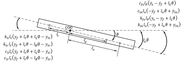
The free body diagram for pitching DOF of fuselage is shown in Fig. 4.
Equation of motion is derived using Newton’s second law of motion as follows:
Similarly, equations of motion for all eleven DOF of the discretized system are derived and expressed in a matrix form as follows:
where, [], [] and [] are the mass, stiffness and damping matrices respectively.
The mass, stiffness and damping matrices are given in Eqs. (3-5):
, and { are the displacement, velocity and acceleration vectors respectively. The displacement vector is given by:
The undamped free-vibration characteristic expression is written as:
The system parameters and geometric dimensions for aircraft is taken from Sivakumar [2] and for biodynamic pilot model is taken from Liang and Chiang [4]. The detailed parameter values considered for analysis is tabulated in Table 1. Eq. (7) is used to extract the natural frequencies, responses and mode shapes of the system. Table 2 indicates the natural frequencies obtained for the present work. Fig. 5 shows the bouncing response of nose tyre, Fig. 6 shows bouncing response of fuselage, Fig. 7 shows pitching response of fuselage and Fig. 8 shows bouncing response of pilot’s head respectively. These responses are extracted for a duration of 2 sec in MatLab.
3. Results and discussions
Modal analysis approach is more feasible for multi-degrees of freedom vibration systems to study the dynamic characteristics as mentioned by Inman [7]. The mathematical model is converted into MatLab code for studying free vibration characteristics. The approach involves formulation of eigen value problem using mass normalization technique with the help of inbuilt “eig” function in MatLab software.
Table 1System parameters and geometric dimensions of aircraft system
Description | Symbol | Value | Units |
Mass of nose tyre | 130 | (Kg) | |
Mass of left tail tyre | 260 | (Kg) | |
Mass of right tail tyre | 260 | (Kg) | |
Mass of fuselage | 22×103 | (Kg) | |
Moment of inertia about axis | 100×109 | (Kg-mm2) | |
Moment of inertia about axis | 65×109 | (Kg-mm2) | |
Mass of pilot’s seat | 15 | (Kg) | |
Mass of thigh and pelvis | 36 | (Kg) | |
Mass of lower torso | 5.5 | (Kg) | |
Mass of upper torso | 15 | (Kg) | |
Mass of head | 4.17 | (Kg) | |
Stiffness of nose tyre | 1.59×10³ | (N/mm) | |
Stiffness of left tail tyre | 1.59×10³ | (N/mm) | |
Stiffness of right tail tyre | 1.59×10³ | (N/mm) | |
Stiffness of nose landing gear | 6.73×10³ | (N/mm) | |
Stiffness of left tail landing gear | 4.08×10³ | (N/mm) | |
Stiffness of right tail landing gear | 4.08×10³ | (N/mm) | |
Stiffness of seat | 31 | (N/mm) | |
Stiffness of pelvis | 49.34 | (N/mm) | |
Stiffness between lower torso and pelvis | 2×10⁴ | (N/mm) | |
Stiffness between upper torso and pelvis | 144 | (N/mm) | |
Stiffness between upper torso and lower torso | 1×10⁴ | (N/mm) | |
Stiffness of head and neck | 166.99 | (N/mm) | |
Damping coefficient of nose tyre | 4.066 | (Ns/mm) | |
Damping coefficient of left tail tyre | 4.066 | (Ns/mm) | |
Damping coefficient of right tail tyre | 4.066 | (Ns/mm) | |
Damping coefficient of nose landing gear | 143 | (Ns/mm) | |
Damping coefficient of left tail landing gear | 625 | (Ns/mm) | |
Damping coefficient of right tail landing gear | 625 | (Ns/mm) | |
Damping coefficient of seat | 0.83 | (Ns/mm) | |
Damping coefficient of pelvis | 2.475 | (Ns/mm) | |
Damping coefficient between lower torso and pelvis | 0.33 | (Ns/mm) | |
Damping coefficient between upper torso and pelvis | 0.9091 | (Ns/mm) | |
Damping coefficient between upper torso and lower torso | 0.2 | (Ns/mm) | |
Damping coefficient of head and neck | 0.31 | (Ns/mm) | |
Distance between COG and nose tyre along axis | 7760 | (mm) | |
Distance between COG and tail tyres along axis | 1940 | (mm) | |
Distance between COG and left tail tyre parallel to axis | 1500 | (mm) | |
Distance between COG and right tail tyre parallel to axis | 1500 | (mm) | |
Distance between COG and pilot’s seat along axis | 7000 | (mm) |
The natural frequencies are obtained as shown in Table 2.
The undamped free vibration response curves are plotted for an initial displacement input of 0.001 m and 0.002 m to nose tyre mass. The response curves for vertical motions of nose tyre, fuselage and head and angular pitching motion of fuselage are as shown in Figs. 5-8.
Table 2Natural frequencies
Mode | (Hz) |
1 | 0.75 |
2 | 1.02 |
3 | 2.48 |
4 | 3.03 |
5 | 11.56 |
6 | 12.69 |
7 | 13.95 |
8 | 13.96 |
9 | 17.59 |
10 | 21.08 |
11 | 37.00 |
Fig. 5Response of nose tyre (ytn vs time graph)
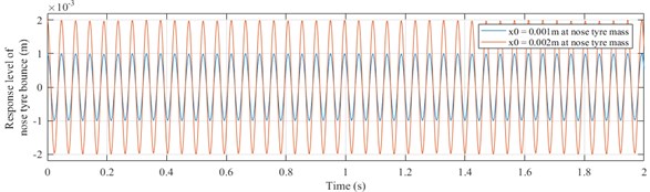
Fig. 6Response of fuselage bouncing (yf vs time graph)
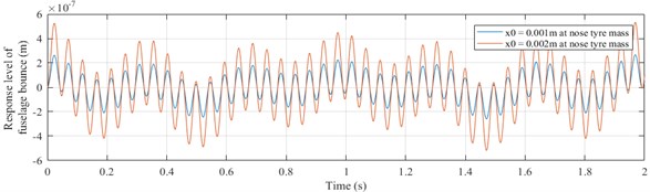
Fig. 7Response of fuselage pitching (θ vs time graph)
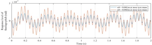
Fig. 8Response of pilot’s head mass (yh vs time graph)
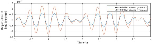
It is observed that the response curves are sinusoidal functions of time. As the initial displacement increases, the amplitude of vibration also increases. The amplitude of vibration of fuselage bouncing is in the order of 10-7 m which is very less compared to the amplitude of bouncing of nose tyre and pilot’s head mass having an order of 10-3 m. It is observed that the natural frequencies obtained doesn’t fall in the sensitive range of 4-10 Hz for a human, according to ISO 2631-1 standard.
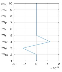
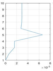
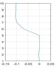
An aircraft system along with pilot is discretized into nine DOF model having vertical displacement motions is considered neglecting the angular pitching and rolling motions. The relative vibrational amplitudes of all masses in the first three predominant modes corresponding to the first three natural frequencies are shown in Fig. 9.
Left and right tail tyre masses move in opposite directions and other masses remain stationary in the first mode. In the second and third modes, all nine masses move relatively in the same direction.
Fig. 9First three mode shapes of nine DOF aircraft system
a)
b)
c)
4. Conclusions
Mathematical model for a discretized eleven DOF aircraft with an integrated biodynamic pilot model is developed. Modal analysis approach is adapted to retrieve dynamic characteristics for a free vibration analysis in MatLab interface. The obtained natural frequencies, mode shapes and undamped response curves are reported. Future studies can be extended to the following fields of study:
1) Study of dynamic characteristics of a combined aircraft and biodynamic pilot system under various operating conditions like landing impact and runway maneuverings.
2) Further discretization of aircraft system and finding its dynamic characteristics.
References
-
Freymann R. An Experimental-Analytical Routine for the Dynamic Qualification of Aircraft Operating on Rough Runway Surfaces. AGARD Report 731, 1987.
-
Sivakumar S., Haran A. P. Mathematical model and vibration analysis of aircraft with active landing gears. Journal of Vibration and Control, Vol. 21, Issue 2, 2015, p. 229-245.
-
Gniady John, Bauman John Active seat isolation for construction and mining vehicles. 42nd Earthmoving Industry Conference Peoria, 1991.
-
Liang Cho Chung, Chiang Chi Feng A study on biodynamic models of seated human subjects exposed to vertical vibration. International Journal of Industrial Ergonomics, Vol. 36, 2006, p. 869-890.
-
Abbas W., Abouelatta O. B., El Azab M., Elsaidy M., Megahed A. A. Optimization of biodynamic seated human models using genetic algorithms. Engineering, Vol. 2, Issue 9, 2010, p. 710-719.
-
Hakan Yazici, Mert Sever Observer based optimal vibration control of a full aircraft system having active landing gears and biodynamic pilot model. Shock and Vibration, Vol. 2016, 2016, p. 2150493.
-
Inman Daniel J. Engineering Vibration. Fourth Edition, Upper Saddle River, 2001.
-
Mechanical Vibration and Shock Evaluation of Human Exposure to Whole Body Vibration. International Standardization Organization, ISO 2631-1:1997(E), 1997.
About this article

