Abstract
Experimental modal analysis, dynamic modeling and parameter identification is employed to investigate the in-plane vibration modal characteristic of a heavy-loaded radial tire with a larger flat ratio. In-plane vibration characteristic of heavy-loaded radial tire is modeled as flexible beam on modified elastic foundation model and flexible tread and distributed sidewall are respectively modeled as the Euler beam and distributed mass element with sectional stiffness. Analytic relationship between the modal resonant frequency and the structural parameters is solved and derived with modal expansion method. The in-plane coupling modal between the flexible tread and sidewall is investigated experimentally. The unknown structural parameters are identified by the genetic algorithm based on the experimental and analytical modal parameter. The higher order modal frequency is predicted with the identified structural parameters and the influence of structural parameters on the modal parameters is compared. Experimental and theoretical result shows that: the experimental modal analysis and theoretical modeling method with the coupling feature of flexible tread, distributed sidewall and rim can accurately characterize the in-plane vibration feature of heavy-loaded radial tire within the frequency band of 300 Hz, compared with the method which only considers the flexible feature of tread and is limited to 180 Hz.
1. Introduction
As the only component interfacing with the road, the heavy-loaded radial tire plays an important role in the heavy-loaded vehicle system [1]. The main performance index of the vehicle, such as smoothness [2], power, economy, maneuverability [3], stability of operation, etc., is closely related to the tire dynamics resulting from the three fundamental functions [4] of heavy-loaded tire, including: (1) generating proper forces during vehicle cornering or traction/braking; (2) absorbing the vibration caused by road irregularity; (3) supporting the vehicle weight on various terrains.
The well-known knowledge of the tire characteristic lays the basic for the development of intelligent vehicle/tire and the design of a pneumatic tire is vital to vehicle dynamics such as handling conditions, different irregular road surface conditions [5] and driving condition. The wide application condition needed to be simulated in more wide frequency range. With respect to noise, the vibration and harshness surface structures of tire patch length and shorter need to be taken into account.
In-plane characteristics of radial tire including the vertical vibration of the tire, enveloping characteristics [6], and rolling resistance [7], etc., directly affect the ride comfort of vehicle, acoustic noise, power performance and fuel economy. Because of the extremely complex structures, material nonlinearity and geometrical nonlinearity of heavy-loaded radial tire, the analytical characteristics of in-plane testing and modeling belongs to one of the difficult points of vehicle dynamics research. Non-linear finite element method [8], ANCF finite element [9], wave finite element [10] and spectral element formulation [11] can describe the structural and material feature in detail and detail tire model is suitable for tire design. Detail tire model, coupling modeling with finite element road model can be used to analyze the coupled vibration, contact stress and wear of tire and road [12]. Due to the comprehensive computation and the difficult obtained material parameters, detail tire model is limited for vehicle simulation appliance. So, the finite element can be applied and optimized in structural design, and even though it is a little bit difficult to satisfy the simulation of durability and ride comfort.
With the feature of high pressure, low damping, bulky decorative pattern and larger flat ratio, the vibration response of rim caused by the irregular road during rolling is owned to the structure vibration, especially for speed exceeding 70 km/h, and the ratio of structural noise and tire noise reached 65 % [13]. Avoiding the high cost and time consuming feature of experimental method, the analytical method based on structural characteristic is becoming more and more significant. As the respective of structural model, flexible tread tire model [14] simplified the tire as the flexible tread on elastic foundation, in which tread referred as flexible continuous tread, sidewall and inflation pressure referred as elastic foundation. Derived by the physical model, flexible tread tire model takes the material nonlinearity and geometrical nonlinearity [15] into consideration, so flexible tread tire model can be used to simulate the in-plane vibration within the wider frequency band and the analytical solution of in-plane vibration characteristics can be gained.
Existing research mostly focused on the dynamic characteristics analysis of cars, passenger cars and trucks. The analytical method with coupling vibration of tread and rim is validated to be sufficient for analyze the in-plane modal feature by experimental modal test [16] and theoretical model [17]. According the different model method of the tread F-tire model can be divided into tensile string model [18], Euler beam model [19], Timoshenko beam model [20], ring model [21] and orthotropic plate [22] or shell model [23]. Tensile string tire model models the inflation pressure as the tensile force, while the bending feature is ignored. Euler beam tire model takes the inflation pressure and bending stiffness of tread into consideration which is validated as the main factor of in-plane vibration within the low or medial frequency band [21]. The shearing action of tread is added which is of vital importance for high frequency vibration above 1 KHz [20]. The Tensile string tire model, Euler beam tire model and Timoshenko tire model belongs to the two-dimension tire model and the bending feature along the tread width direction is considered which forms the three-dimension tire model, including: orthotropic plate [22] or shell model [23]. Existing paper main focused on the flexible deformation of the tread [24] and the stiffness feature of sidewall which is effective to analyze the in-plane vibration of tire for cars, passenger cars and trucks, and the research on the experimental modal analysis of heavy-load radial tire is rarely.
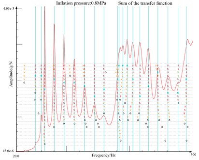
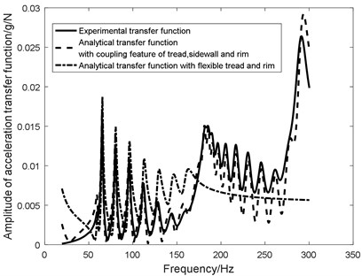
As the structural feature of the larger flat ratio, the in-plane vibration characteristic of heavy-loaded radial tire is different from that of tire of cars, passenger cars and trucks. The in-plane transfer function illustrated in Fig. 1 shows the sectional feature of two different vibration characteristic featured with different stiffness and mass characteristic within 300 Hz, which agrees with the research of Hoever [25].
Fig. 1The transfer functions of tread exciting and tread responding
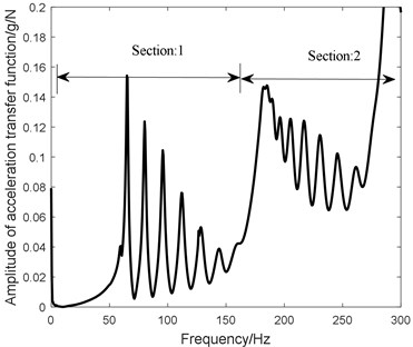
In order to take the different vibration characteristic between the 0-180 Hz and 180-300 Hz into consideration, the traditional elastic foundation is modified to add the sectional radial stiffness and the inertia feature. Base on the proposed flexible beam on modified elastic foundation tire model, the experimental modal analysis, dynamic modeling and parameter identification is utilized to research the in-plane vibration characteristic of heavy-loaded radial tire.
The rest of the paper is organized as follows: The coupling dynamics of flexible beam on modified elastic foundation is derived and simulated in Section 2 “Theoretical modeling”. The in-plane modal feature is researched experimentally in Section 3 “In-plane experimental modal analysis”. The un-known structural parameters are identified utilizing Genetic Algorithm based on the analytical and experiment modal parameters presented in Section 4 “Structural parameters identification”. The influence of different structural parameters on the modal frequency is derived and compared in Section 5 “Parametric analyses”.
2. Theoretical modeling
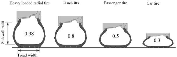
Heavy-loaded radial tire-GL073A ADAVANCE tire has the characteristics of load heavily and to ensure its off-road properties, heavy-loaded radial tire is equipped with larger flat ratio (Fig. 2), compared with passenger car tire and truck tire. The structural parameters are list below:16.00R20 173G, 18 ply rating, maximum speed is (90 km/h), section width is 438 mm, outside diameter is 1320 mm, normal inflation pressure is 800 KPa, maximum load is 6500 kg.
Fig. 2Flat ratio of different kinds of tire
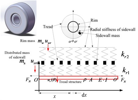
The flexible beam on modified elastic foundation tire model (Fig. 3) consisted with two critical sections:
1) Tread is simulated as Euler beam and the pre-tension force resulting from the inflation pressure is modeled as the axis force of the Euler beam;
2) Sidewall is simulated as the two-sectional radial stiffness and the inertia force.
Fig. 3Flexible beam on modified elastic foundation
2.1. Coupling dynamics of tread and sidewall
Hypothesis:
1) The cross section of inertia axis of tread beam is in the same plane, in the plane ;
2) Transverse vibration of tread belongs to micro-vibration;
3) Beam bending deformation is the main deformation, shear deformation and the influence of moment of inertia of cross section around the neutral axis can be ignored in the low frequency vibration.
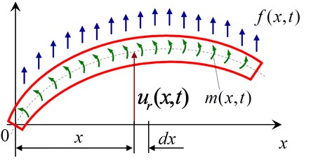
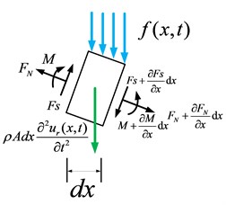
The stress analysis of the micro-segment is shown in Fig. 4. See Fig. 4, , are respectively shear and bending moments of cross section; is the horizontal displacement of the cross section at the time at the point from the original point of the beam and ; is the inertial forces on the micro-segment; is external forces of the micro-section; is external moment of the microsegment; is pre-tension caused by the inflating pressure.
Fig. 4Force analysis of micro-section of flexible tread
a)
b)
Equation of force balance [19]:
Equation of moment balance [19]:
The relationship between bending moment and deflections derived:
where is elasticity modulus; is inertia moment of cross section and .
Substituting Eqs. (2, 3) into Eq. (1) and the dynamics equation of flexible tread is given as:
where 0 and .
Substituting into Eq. (4) and the dynamics equation of flexible tread is obtained as:
The interaction between the flexible tread and distributed sidewall element refers as the spring force and the in-plane vibration equation of heavy-loaded tire with a larger flat ratio adding two-sectional radial stiffness and the inertia force of sidewall:
where Eq. (6a) is the bending vibration equation of flexible tread; Eq. (6b) is the radial vibration equation of distributed sidewall element; Eq. (6c) is the vibration equation of rim.
2.2. Dynamics solving
With the means of modal expansion method, the in-plane coupling equation Eq. (6) of heavy-loaded radial tire is transformed into the time domain and space domain respectively the free vibration mode of space domain is assumed in the sinusoidal series given in Eq. (7):
The vibration equation of rim is obtained as:
Eq. (8) implies:
1) Rim is coupling with sidewall only for the first order;
2) As 1, 0;
3) The high order modal of flexible tread and sidewall element is independent with the vibration of rim.
The simplified equation of rim vibration :
1) 1, the in-plane dynamics of heavy-loaded radial tire are given as:
Namely:
2) 1, the coupling dynamics of heavy-loaded radial tire are referred as:
Namely:
The high order ( 1) vibration characteristic of heavy-loaded radial tire is independent with the freedom of the rim and the dynamic equation Eq. (13) is simplified as:
The analytical modal resonant frequency is obtained as:
where:
3. In-plane experimental modal analysis
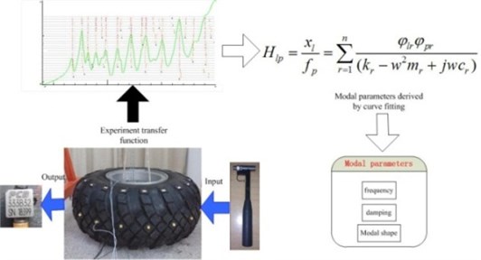
Tire modal performance plays an important role in heavy-loaded vehicles NVH refinement. By means of measuring the acceleration response of the heavy-loaded radial tire, caused by a hammer or shaker, a frequency response function can be obtained. The modal parameters including: modal resonant frequency, modal damping and modal shape can be obtained by curve fitting, which the scheme of modal analysis is shown in Fig. 5.
Fig. 5Scheme of experimental modal analysis
3.1. System description and implement
The modified modal analysis method with the coupling characteristic of tread, sidewall and rim is proposed and implemented, which is shown in Fig. 6(b) and compared with the modal analysis method with flexible tread (Fig. 6(c)) [26]. Fig. 6(a) illustrates the hardware equipment, including: tire support device, force hammer, charge amplifier, data test system and PC computer.
Fig. 6System configuration of experimental modal analysis with the coupling characteristic of tread, sidewall and rim
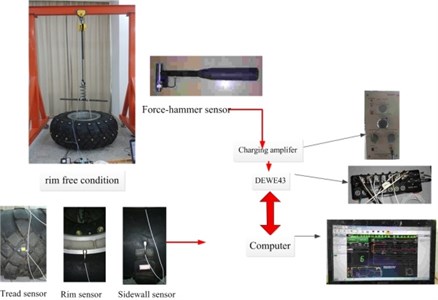
a) Hardware equipment of the modal test
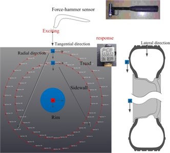
b) Incentive method
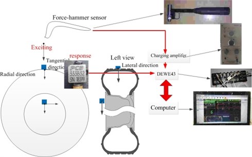
c) Modal analysis with the flexible feature of tread
The flexible tread is divided into 34 sections shown in Fig. 6(b). With the PCB acceleration sensor pasted respectively on the flexible tread, sidewall and rim, the experimental modal test is implemented by moving hammer method along the radial tire tread. The input force is measured by the B&K force hammer transducer and the signal is conditioned by the charging amplifier. The excited force and the responding acceleration are gathered by DE-43 data collector and dynamic signal analyze then computes the desired transfer function.
3.2. Modal analyses with the coupling of tread, sidewall and rim
The transfer function of tread radial response-tread radial excitation, sidewall radial response-tread radial excitation, rim radial response-tread radial excitation is summed up and least squares complex exponential method (LSCE) [27] (Fig. 7) is used to estimate the frequency (in Appendix), damping (in Appendix), participation factor and modal shape (in Appendix).
Fig. 7Scheme of modal analysis
In order to validate the orthogonal modal vectors, MAC matrix (Modal assurance criterion) between each order modal value is computed in Fig. 8(a) compared with that of coupling modal test of flexible tread and rim (Fig. 8(b)). Meanwhile, Fig. 9 shows experimental transfer function, analytical transfer function with coupling feature of tread, sidewall and rim and analytical transfer function with flexible tread and rim.
Fig. 8MAC value
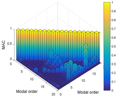
a) MAC of coupling modal for tread, sidewall and rim
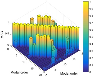
b) MAC of flexible tread and rim
The analysis results of in-plane experimental modal (in Appendix), Figs. 8, 9 imply:
1) Fig. 8 shows that MAC value of coupling modal analysis of tread, sidewall and rim is compared with the MAC value of only coupling modal analysis of tread and rim. MAC value of coupling modal analysis of tread, sidewall and rim is less than 0.2, while eight pairs of MAC value of only coupling modal analysis of tread and rim, such as the first and ninth order, second and the tenth order, third and eleventh order, the forth and twelfth order, the fifth and thirteenth order, the sixth and fourteenth order, the seventh and fifteenth order, the eighth and sixteenth order is 1, illustrating the linear relationship with each other;
2) The experimental transfer function is compared with analytical transfer function with coupling feature of tread, sidewall and rim and analytical transfer function with flexible tread and rim in Fig. 9. The compared result shows that the analytical transfer function with flexible tread and rim is unable to character the vibration feature above 180 Hz, while the analytical transfer function with coupling feature of tread, sidewall and rim agrees with the experimental transfer function well;
3) The in-plane vibration character can be featured as harmonic characteristic seen from the modal shape (in Appendix). The modal shape is referred as the same-directional vibration of tread and sidewall within the frequency band 0-180 Hz, while within the frequency band 180-300 Hz, the modal shape is featured as the opposite-directional vibration of tread and sidewall.
4) The different coupling vibration characteristic of tread and sidewall can be explained as that the structural and operative feature: overloading inflation pressure, heavier load, larger flat ratio and larger mass ratio, makes the resonant wavelength longer and reduces the resonant frequency compared with other kinds of tire, such as passenger car tire and truck tire;
5) The analytical method with the coupling feature of tread, sidewall and rim is effective to character the vibration of frequency band within 300 Hz.
Fig. 9Amplitude of analytical transfer function
4. Structural parameters identification
The unknown structural parameters are identified based on the analytical and experimental modal parameters using Genetic Algorithm (GA) by combining the survival of fittest rules, the random information exchanging mechanism of chromosomes and genetic operation as selection, crossover, and mutation [28].
Table 1 lists the geometrical and structural parameters of heavy-loaded tire illustrated in Eqs. (14, 15).
4.1. Parameters identification
In order to achieve the optimal solution, GA uses the fitness function to evaluate each individual, and gains the better group based on evolutionary rules, the optimization process shown in Fig. 10.
Table 1Geometrical and structural parameters of GL073A tire
Parameters | Symbol | Unit | Value |
Tread width | 0.35 | ||
Inflation pressure | N/m2 | 8×10⁵ | |
Tire radii | 0.65 | ||
Density per rad of sidewall | kg/rad | 10 | |
Density per line of tread | kg/m | 19.64 | |
Radial stiffness connecting the sidewall and tread | N/m | Under-identified | |
Radial stiffness connecting the sidewall and rim | N/m | Under-identified | |
Bending stiffness of tread | N/m | Under-identified |
Fig. 10Scheme of the structural parameters identification
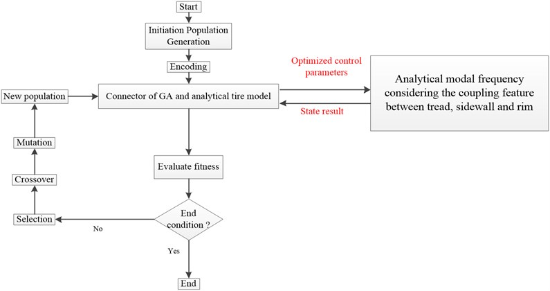
4.1.1. Implement of GA
Step 1: Algorithm initializing; the structural parameters of genetic algorithm is presented as Table 2.
Table 2Initial parameters of GA
Parameters | Valve | Parameters | Parameters |
Population size | 20 | Crossover rate | 0.7 |
Number of generations | 300 | Mutation rate | 0.1 |
Generation gap | 0.9 | ||
Step 1: Encoding scheme.
The real-coded scheme is used to transform the parameter space into bit string representations and individuals are coded as vectors of real numbers corresponding to the design variables.
Step 2: Evaluating fitness.
The fitness is evaluated in every generation depending on the objective function value and the less error is mapping with higher fitness advances to the next generation.
The error between the experimental and analytical modal resonant frequency is chosen as the object value and four modal parameters pairs such as three-sectional modal shape, four-sectional modal shape, five-sectional modal shape and six-sectional modal shape are selected.
In order to simplifying the computation process, the two variable calculated from the analytical and experimental modal resonant frequency is chosen as the standard data given as Eqs. (16, 17):
The error of analytical modal frequency Eq. (18) and the experimental modal frequency (in Appendix) is chosen as the object function, referred as Eq. (21):
Step 3: Crossover.
One-point crossover is proposed and offspring is formed by combining the best individuals with the genetic information.
Step 4: Mutation.
Mutation is utilized to diversify the population as different areas of the parameters space and also prevent the solution from premature convergence.
Step 5: After selection, crossover and mutation are applied to the initial population, a new population will be formed and the generational counter is increased by one.
4.1.2. Analysis of parameters identification
Fig. 11 shows the object value and structural parameters of optimization process and the identified results of structural parameters are shown in Table 3.
Table 3Identified result of GA
Parameters | Symbol | Unit | Identified value |
Radial stiffness connecting the sidewall and tread | N/m | 6.686×10⁶ | |
Radial stiffness connecting the sidewall and rim | N/m | 4.431×10⁶ | |
Bending stiffness of tread | N/m | 25.697 |
The results of optimization procedure (Fig. 11) imply that:
1) The object value is close to the steady point when the optimization procedure proceeds to 100 generations, which is convergent;
2) The under-identified structural parameters, including: bending stiffness , sidewall stiffness , approach the identified result as the optimization procedure proceeding 100 generations and converge to the optimum solution.
4.2. Prediction of analytical modal frequency
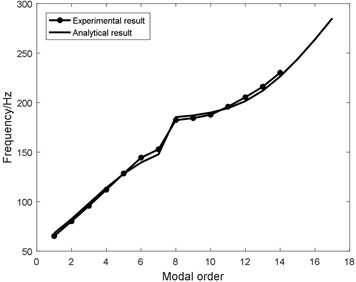
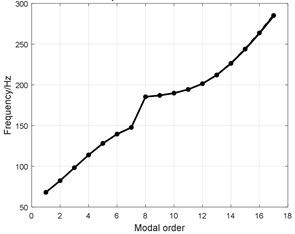
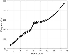
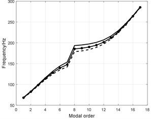
In order to validate the reality of the identified structural parameters, the analytical modal frequency is predicted and compared with the experimental modal frequency in Fig. 12.
The compared results imply that:
1) The prediction result of analytical heavy-loaded radial tire fits the experimental result and the error is limited within 5 % shown in the Fig. 12;
2) The tendency of modal frequency experimentally and analytically within the two frequency band: 0-180 Hz, 180-300 Hz is different resulting from the different vibration direction of tread and sidewall;
Structural features of larger flat ratio and larger mass ratio makes the resonant wavelength of tread and sidewall longer and decreases the resonant frequency to 180 Hz. So, the vibration characteristic within frequency band of 0-180 Hz is the same directional shape, while the vibration characteristic within frequency band of 180-300 Hz is the opposite directional shape.
Fig. 11Variables of optimization procedure
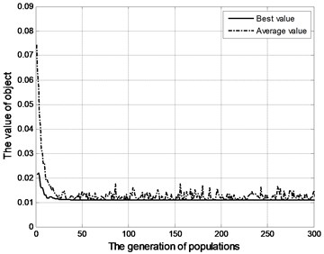
a) Object value
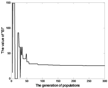
b) Bending stiffness
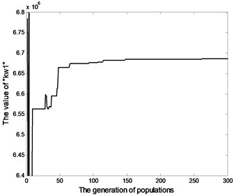
c)Sidewall stiffness
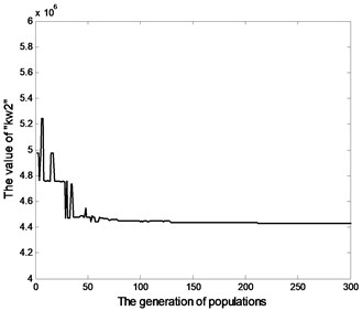
d) Sidewall stiffness
Fig. 12Analytical modal frequency based on the identified structural parameters
5. Parametric analyses
The analytical modal frequency of the shape with the same direction vibration feature of tread and sidewall is referred as Eq. (19):
While the analytical modal frequency of the shape with the opposite direction vibration feature of tread and sidewall is referred as Eq. (20):
The key structural parameters including: , and belonging to the structural parameters of tread and , belonging to the structural parameters of sidewall are analyzed and simulated below.
5.1. Structural parameters of tread
Initial parameters of heavy-loaded radial tire are referred as Table 4 and the single variable method is presented and proposed.
The structural parameters with 80 percent, 100 percent and 120 percent of single parameters of tread structural parameters are compared in Tables 4-6 and the compared modal resonant frequencies are shown in Fig. 13.
Table 4Bending stiffness of tread beam EI
Parameters | Symbol | Unit | Value | Value | Value | |
Structural parameters of tread | Bending stiffness of tread | N/m | 25.697 | 25.697×0.8 | 25.697×1.2 | |
Density per line of tread | kg/m | 19.64 | 19.64 | 19.64 | ||
Tread width | m | 0.35 | 0.35 | 0.35 | ||
Structural parameters of sidewall | Density per rad of sidewall | kg/rad | 10 | 10 | 10 | |
Radial stiffness connecting the sidewall and tread | N/m | 6.686×10⁶ | 6.686×10⁶ | 6.686×10⁶ | ||
Radial stiffness connecting the sidewall and rim | N/m | 4.431×10⁶ | 4.431×10⁶ | 4.431×10⁶ |
Table 5Density per line of tread ρA
Parameters | Symbol | Unit | Value | Value | Value | |
Structural parameters of tread | Bending stiffness of tread | N/m | 25.697 | 25.697 | 25.697 | |
Density per line of tread | kg/m | 19.64 | 19.64×0.8 | 19.64×1.2 | ||
Tread width | m | 0.35 | 0.35 | 0.35 | ||
Structural parameters of sidewall | Density per rad of sidewall | kg/rad | 10 | 10 | 10 | |
Radial stiffness connecting the sidewall and tread | N/m | 6.686×10⁶ | 6.686×10⁶ | 6.686×10⁶ | ||
Radial stiffness connecting the sidewall and rim | N/m | 4.431×10⁶ | 4.431×10⁶ | 4.431×10⁶ |
Table 6Tread width b
Parameters | Symbol | Unit | Value | Value | Value | |
Structural parameters of tread | Bending stiffness of tread | N/m | 25.697 | 25.697 | 25.697 | |
Density per line of tread | kg/m | 19.64 | 19.64 | 19.64 | ||
Tread width | 0.35 | 0.35×0.8 | 0.35×1.2 | |||
Structural parameters of sidewall | Density per rad of sidewall | kg/rad | 10 | 10 | 10 | |
Radial stiffness connecting the sidewall and tread | N/m | 6.686×10⁶ | 6.686×10⁶ | 6.686×10⁶ | ||
Radial stiffness connecting the sidewall and rim | N/m | 4.431×10⁶ | 4.431×10⁶ | 4.431×10⁶ |
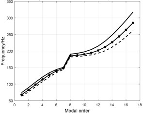
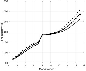
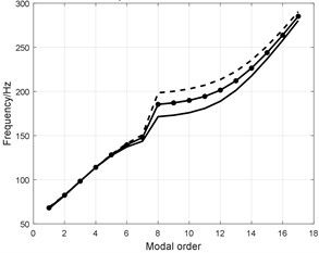
Fig. 13Influence analysis of tread structural parameters
a) Bending stiffness of tread beam
b) Density per line of tread
c) Tread width
5.2. Structural parameters of sidewall
The single variable method is proposed. The structural parameters with 80 percent, 100 percent and 120 percent of single parameters of sidewall structural parameters are compared as Tables 7-9, Fig. 14.
Table 7Density per rad of sidewall ms
Parameters | Symbol | Unit | Value | Value | Value | |
Structural parameters of tread | Bending stiffness of tread | N/m | 25.697 | 25.697 | 25.697 | |
Density per line of tread | kg/m | 19.64 | 19.64 | 19.64 | ||
Tread width | m | 0.35 | 0.35 | 0.35 | ||
Structural parameters of sidewall | Density per rad of sidewall | kg/rad | 10 | 10×0.8 | 10×1.2 | |
Radial stiffness connecting the sidewall and tread | N/m | 6.686×10⁶ | 6.686×10⁶ | 6.686×10⁶ | ||
Radial stiffness connecting the sidewall and rim | N/m | 4.431×10⁶ | 4.431×10⁶ | 4.431×10⁶ |
The result of parametric analysis for heavy-loaded radial tire shown in Figs. 13-14 implies that:
1) The influence of bending stiffness on the analytical modal frequency is not apparent shown in Fig. 13(a) and the effect is apparent in the high order modal. The bending stiffness effect the high order modal frequency;
2) The augmented density per line of tread reduces the modal frequency shown in Fig. 13(b);
3) The augmented tread width increases the modal frequency shown in Fig. 13(c);
4) The augmented radial stiffness increases the modal frequency shown in Fig. 14(a). The effect on the low order shape of opposite direction of tread and sidewall is especially apparent and as the order increasing the effect becomes not apparent;
5) The augmented radial stiffness increases the modal frequency shown in Fig. 14(b). Radial stiffness affects on the low order shape of opposite direction of tread and as the order increasing the effect becomes not apparent;
6) The augmented density per rad of sidewall reduces the modal frequency shown in Fig. 14(c).
Table 8Radial stiffness connecting the sidewall and tread kr1
Parameters | Symbol | Unit | Value | Value | Value | |
Structural parameters of tread | Bending stiffness of tread | N/m | 25.697 | 25.697 | 25.697 | |
Density per line of tread | kg/m | 19.64 | 19.64 | 19.64 | ||
Tread width | m | 0.35 | 0.35 | 0.35 | ||
Structural parameters of sidewall | Density per rad of sidewall | kg/rad | 10 | 10 | 10 | |
Radial stiffness connecting the sidewall and tread | N/m | 6.686×10⁶ | 6.686×0.8×106 | 6.686×1.2×106 | ||
Radial stiffness connecting the sidewall and rim | N/m | 4.431×10⁶ | 4.431×10⁶ | 4.431×10⁶ |
Table 9Radial stiffness connecting the sidewall and rim kr2
Parameters | Symbol | Unit | Value | Value | Value | |
Structural parameters of tread | Bending stiffness of tread | N/m | 25.697 | 25.697 | 25.697 | |
Density per line of tread | kg/m | 19.64 | 19.64 | 19.64 | ||
Tread width | m | 0.35 | 0.35 | 0.35 | ||
Structural parameters of sidewall | Density per rad of sidewall | kg/rad | 10 | 10 | 10 | |
Radial stiffness connecting the sidewall and tread | N/m | 6.686×10⁶ | 6.686×10⁶ | 6.686×10⁶ | ||
Radial stiffness connecting the sidewall and rim | N/m | 4.431×10⁶ | 4.431×0.8×106 | 4.431×1.2×106 |
Fig. 14Influence analysis of sidewall structural parameters
a) Radial stiffness
b) Radial stiffness
c) Density per rad of sidewall
6. Conclusions
The in-plane vibration modal of heavy-loaded radial tire with the coupling feature of flexible tread, distributed sidewall and rim is analyzed theoretically and validated experimentally, including:
1) The in-plane vibration modal test and analysis with the coupling feature of flexible tread, distributed sidewall and rim is proposed and implemented;
2) The flexible beam on modified elastic foundation is presented and researched;
3) The structural parameters are identified, and the identification result is validated with the experiment result;
4) The influence of structural parameters on the in-plane modal frequency is discussed and compared.
The main results are concluded:
1) The in-plane vibration of heavy-loaded radial tire refers as the same-direction modal shape within 0-180 Hz and the opposite-direction modal shape within 180 Hz-300 Hz;
2) The experimental modal test and analysis with the coupling feature of flexible tread, distributed sidewall and rim reveals the in-plane vibration characteristic of heavy-loaded radial tire and lays the foundation of the theoretical analysis;
3) The coupling dynamics of heavy-loaded radial tire with the coupling feature of flexible tread, distributed sidewall and rim is derived and the analytical expression is given based on the geometrical and structural parameters;
4) The flexible beam on modified elastic foundation tire model can achieve to character the in-plane vibration of heavy-loaded radial tire;
5) The backward parameters identification based on the experimental and analytical modal parameters can achieve the prediction of high order modal frequency and the error is limited within 5 %, compared with the experimental result.
6) The influence on the analytical modal frequency of structural parameters is researched that radial stiffness , affecting the low order modal frequency and the bending stiffness affecting the high order modal frequency.
References
-
Li Shaohua, Yang Shaopu, Chen Liqun Investigation on cornering brake stability of a heavy-duty vehicle based on a nonlinear three-directional coupled model. Applied Mathematical Modelling, Vol. 40, 2016, p. 6310-6323.
-
Wang Rongrong, Hu Chuan, Wang Zejiang, Yan Fengjun, Chen Nan Integrated optimal dynamics control of 4WD4WS electric ground vehicle with tire-road frictional coefficient estimation. Mechanical Systems and Signal Processing, Vol. 60, Issue 61, 2015, p. 727-741.
-
Li Bin, Yang X., Yang J. Tire model application and parameter identification-a literature review. SAE International Journal of Passengers Cars-Mechanical System, 2014, p. 0872.
-
Pazooki Alireza, Rakheja Subhash, Cao Dongpu Modeling and validation of off-road vehicle ride dynamics. Mechanical Systems and Signal Processing, Vol. 28, 2012, p. 679-695.
-
Li Bin, Yang X., Zhang Y., Yang J. In-plane flexible ring tire model development for ride comfort & braking/ driving performance analysis under straight-line driving condition. SAE Technical Paper, 2015, p. 0628.
-
Fan Chengjian, Guan Dihua The quantitative analysis and experimental verification of the tire static enveloping model using experimental modal parameters. Vehicle System Dynamics, Vol. 44, Issue 9, 2006, p. 675-688.
-
Ajp Miege, Popov A. A. Truck tyre modelling for rolling resistance calculations under a dynamic vertical load. Proceedings of the Institution of Mechanical Engineers, Part D: Journal of Automobile Engineering, Vol. 219, 2005, p. 441-456.
-
Stallmann Joachim M., Schalk Els P. Parameterization and modelling of large off-road tyres for ride analyses: Part 2-Parameterization and validation of tyre models. Journal of Terramechanics, Vol. 55, 2014, p. 85-94.
-
Patel Mohil, Orzechowski Grzegorz, Tian Qiang, Shabana Ahmed A. A new multibody system approach for tiremodeling using ANCF finite elements. Proceedings of the Institution of Mechanical Engineers, Part K: Journal of Multi-body Dynamics, Vol. 230, Issue 1, 2016, p. 69-84.
-
Dishan Huang, Liang Tang, Rui Cao Free vibration analysis of planar rotating rings by wave propagation. Journal of Sound and Vibration, Vol. 332, 2013, p. 4979-4997.
-
Delamotte J. C., Nascimento R. F., Arruda J. R. F. Simple models for the dynamic modeling ofrotating tires. Shock and Vibration, Vol. 15, 2008, p. 383-393.
-
Wei Chongfeng, Oluremi Ayotunde Olatunbosun The effects of tyre material and structure properties on relaxation length using finite element method. Materials and Design, Vol. 102, 2016, p. 14-20.
-
Wei Yintao, Oertel Christian, Li Xuebing, Yu Liangyao A theoretical model for the tread slip and the effective rolling radius of the tyres in free rollin. Proceedings of the Institution of Mechanical Engineers, Part D: Journal of Automobile Engineering, 2017, p. 1-10.
-
Wei Yin Tao, Nasdala L., Rothert H. Analysis of forced transient response for rotating tires using REF models. Journal of Sound and Vibration, Vol. 320, Issues 1-2, 2009, p. 145-162.
-
Trong Dai Vu, Denis Duhamel, Zouhir Abbadi, Hai Ping Yin, Arnaud Gaudin A nonlinear circular ring model with rotating effects for tire vibrations. Journal of Sound and Vibration, Vol. 388, 2017, p. 245-271.
-
Lopez I., Blom R., Roozen N., Nijmeijer H. Modelling vibrations on deformed rolling tyres-a modal approach. Journal of Sound and Vibration, Vol. 307, Issues 3-5, 2007, p. 481-494.
-
Jongsuh Lee, Semyung Wang, Bert Pluymers, et al. A modified complex modal testing technique for a rotating tire with a flexible ring model. Mechanical Systems and Signal Processing, Vol. 60, Issue 61, 2015, p. 604-618.
-
Zhou Fenghua, Yu T. X., Yang Liming Elastic behavior of ring-on-foundation. International Journal of Mechanical Sciences, Vol. 54, 2012, p. 38-47.
-
Krylov V. V., Gilbert O. On the theory of standing waves in tyres at high vehicle speeds. Journal of Sound and Vibration, Vol. 329, Issue 21, 2010, p. 4398-4408.
-
Pinnington R. J. A wave model of a circular tyre. Part 1: belt modeling. Journal of Sound and Vibration, Vol. 290, 2006, p. 101-132.
-
Danilo Beli, Priscilla Brand, Jos E. R. Vibration analysis of flexible rotating rings using a spectral element formulation. Journal of Vibration and Acoustics, Vol. 137, Issue 41003, 2015, p. 1-11.
-
Lebot Alain, Bazari Zakia, Klein Philippe, Lelong Joël Statistical analysis of vibration in tyres. Journal of Sound and Vibration, Vol. 392, 2017, p. 187-199.
-
Lecomte C. A., Graham W. R., Dale M. A shell model for tyre belt vibrations. Journal of Sound and Vibration, Vol. 329, 2010, p. 1717-1742.
-
Wang Zhen Feng, Dong Ming Ming, Zhao Wei Peng, Gu Liang A novel tread model for tire modelling using experimental modal parameters. Journal of Vibroengineering, Vol. 19, Issue 2, 2017, p. 1225-1240.
-
Hoever C. The Simulation of Car and Truck Tyre Vibrations, Rolling Resistance and Rolling Noise. Ph.D. Thesis, Chalmers University of Technology, Sweden, 2014.
-
Doria A., Taraborrelli L., Urbani M. A modal approach for the study of the transient behavior of motorcycle and scooter tires. Proceedings of the International Design Engineering Technical Conferences and Computers and Information in Engineering Conference, New York, USA, 2014.
-
De Troyer T., et al. Fast calculation of confidence intervals on parameter estimates of least-squares frequency-domain estimators. Mechanical Systems and Signal Processing, Vol. 23, 2009, p. 261-273.
-
Bagheri M., Jafari A. A., Sadeghifar M. Multi-objective optimization of ring stiffened cylindrical shells using a genetic algorithm. Journal of Sound and Vibration, Vol. 330, 2011, p. 374-384.
Cited by
About this article

