Abstract
The purpose of this research is to prove the eventuality of using a novel adaptive surrogate model for optimization problems. The adaptive surrogate model is based on iteration sampling and extended radial basis function (ERBF). This method improves the precision by a means that new sample points is placed in the blank area and all the sample points is uniformly distributed in the design region. The precision of the surrogate model is checked using standard error measure to determine whether updating the surrogate model or not. Since the prediction of modal frequencies require structure modal simulations. In order to decrease the number of computer simulations, a Multi-Island GA approach is combined with the adaptive surrogate model to find the optimum modal frequencies of a strapdown inertial navigation system for electric helicopters. The strapdown inertial navigation system is comprised of damping material, counterweight material and inertial navigation sensor. This is a multi-objective functions optimization problem since the modal frequencies are considered from mode 1 to mode 6 in this paper. Several weights of multi-objective functions are utilized to research the modal frequencies. The whole number of 15 sampling points is picked to build the primary surrogate model using Latin hypercube sampling (LHS). The results of adaptive surrogate model show that two new sampling points are needed to reform the precision of the surrogate model under the condition of 2 % confidence bounds. The structure modal optimization results show that the choice of the weights for the multi-objective functions has a major effect on the final optimum modal frequencies. Time- and frequency-domain analysis indicated that the optimum modal frequencies are far away from the excitation frequencies to avoid strapdown inertial navigation system resonance as far as possible.
1. Introduction
Vibration is an important issue in helicopters. Rotors operate in a highly complex unsteady aerodynamic environment caused by cyclic variation of aerodynamic loads on the blade. Significant structural vibration due to unsteady aerodynamics caused by free stream, returning wake and elastic blades is a notable and undesirable characteristic of helicopter flight [1]. The most important sources that contribute to the vibration in a helicopter airframe are the rotor hub reactions induced by the inertial and aerodynamic loads acting on the blades. Most of the aerodynamic vibratory loads produced by the rotor system are cancelled at the hub, except for their and harmonics, where is the blade speed, is an arbitrary integer and is the number of blades [2]. Due to the inherent coupling between the rotor system and the airframe, vibratory hub loads are transferred throughout the helicopter structure. So, the strapdown inertial navigation system is affected easily. Since strapdown inertial navigation system is directly installed on the helicopter, they are sensitive to vehicle vibration [3]. Special supports [4] or dampers [5] for strapdown inertial navigation system are used to reduce the vibration. However, structure modal optimization of strapdown inertial navigation system has not been proposed and studied for an electric helicopter with a fixed blade speed. Since a structure model of strapdown inertial navigation system is built for the helicopter in this paper. Damping material and counterweight material (copper alloy) as two kinds of material attributes parameters are used to analyze the modal frequencies. The strapdown inertial navigation system is installed in the flight control box. The flight control box is installed on the helicopter. Since and harmonics of the blade are transferred throughout the strapdown inertial navigation system.
In the modal optimization process of the strapdown inertial navigation system, the surrogate model is used to solve the expensive finite element analysis (FEA) computations problem. Among the available surrogate model techniques, the Response Surface Methodology (RSM) approach was introduced by GEP Box and KB Wilson in 1951. This approach was used to optimize fire performance of ultra-low density fiberboards polynomial by Wu [6] in 2017. Kriging approach was named by French mathematician Matheron in 1963, after the South African mining engineer Krige, as it is still known in spatial statistics today. The Kriging approach is used to optimize the structure of water axial piston pump and cavitation of plunger cavity in 2017 [7]. Radial basis function (RBF) methods are effective multidimensional approximation approaches. The performances of RBF methods are independent of the dimensionality to an extent [8]. A novel approach of extended radial basis function (ERBF) is proposed by Mullur and Messac [9] in 2005. The ERBF approaches are more flexible compare with RSM, Kriging and RBF. Since the ERBF approach is used to build the surrogate model in this research. However, these surrogate model approaches are all have no adaptive capability to the sampling points chosen. In the field of adaptive sampling techniques, Chen [10] used a local adaptive sampling to enhance the efficiency of constructing Kriging models for reliability-based design optimization problems in 2014. But this approach is not applicable if sampling points are close to the limit state boundaries. An adaptive importance sampling technique based on stochastic Newton recursions was used to accurately predict the power penalty induced [11]. Li and Chuang [12] apply Stein’s Unbiased Risk Estimator (SURE) to adaptive sampling and reconstruction to reduce noise in Monte Carlo rendering. Aerodynamic shape of high speed train nose is optimized using adaptive surrogate model [13]. A novel approach for constructing adaptive surrogate models with application in production optimization problem is proposed [14]. However, these approaches are not applicable, considering that increases new sampling points in the blank region after initial training points is selected using LHS. In this paper, an adaptive surrogate model that based on iteration sampling and extended radial basis function is proposed to address this adaptive sampling problem. And this approach is used to optimize the modal frequencies of strapdown inertial navigation system of an electric helicopter for demonstration. Time- and frequency-domain analysis of strapdown inertial navigation system structure is used to prove the correctness of the optimization results.
The remainder of the paper is organized as follows. In Section 2, the introduction to methods of the RBF and ERBF techniques is provided, and an adaptive surrogate model is proposed using iteration sampling and ERBF. In Section 3, the adaptive surrogate model is employed in structure modal optimization of strapdown inertial navigation system for electric helicopter, serving as the case study. In Section 4, time- and frequency-domain analysis of strapdown inertial navigation system structure is researched. Finally, in Section 5, our contributions are summarized.
2. Research method
The structure modal optimization process presented in this paper is divided into two steps. The first step is the building of an adaptive surrogate model. The second step is to combine the adaptive surrogate model with selected optimization algorithm to determine the optimum modal frequencies of the strapdown inertial navigation system.
2.1. Optimization methods
There are several meaningful optimization methods in the optimized research field but one of the most used algorithms in engineering is the Genetic Algorithm (GA). Genetic algorithms are classical stochastic optimization algorithms inspired by evolutionary analogy. Because of their robustness and ease of application, genetic algorithms are used for machine learning, automatic control, and so on. Instead of traditional genetic algorithm, Multi-Island GA is employed for the optimization. In Multi-Island GA, the population is divided into several subpopulations staying on isolated “islands”, whereas traditional genetic algorithm operations are performed on each subpopulation separately. A certain number of individuals between the islands migrate after a certain number of generations. Thus, Multi-Island GA can prevent the problem of “premature” by maintaining the diversity of the population [15]. In addition, the calculation speed of Multi-Island GA can be greater than that of traditional genetic algorithms.
2.2. Extended radial basis function models
The computer simulations to study and analyze designs are very expensive sometimes. In order to achieve the result, large computational resources and the time are needed. Since the problem of simulation cost becomes more severe. ERBF surrogate model based design optimization helps in reducing the number of real computer simulations necessary to solve this problem.
ERBF approaches are the extension of RBF. RBF is expressed according to the Euclidean distance of a generic point from a given point data which can be mathematically defined as:
where is a prescribed parameter. The radial basis function is a linear combination equation, as described by:
where are unknown factor to be solved and represents the number of sampling points, the preceding equations is expressed in matrix form as follow:
where , , are written as:
where is calculated by the Euclidean distance of point and point . The vector are defined by solving the Eq. (3). The Euclidean distances that unknown point in the design domain relative to all date points into:
The interpolation result of RBF for the generic point is expressed as:
The typical RBF approaches provide only an interpolative solving method to the surrogate model problem, but they do not provide patterns for the designer to deliver desirable performance for the meta-models. Mullur A. A. proposed a surrogate model of extended radial basis function [9], they define a coordinate vector as , which is the coordinate of any point in the design domain relative to the sampling point along the th dimension, and define non-radial basis function as:
The functions and are described in Table 1.
Table 1The description of non-radial basis functions
0 | |||
0 | |||
0 | |||
0 |
In Table 1, and are prescribed parameters, extended radial basis function method is a surrogate model approach that combine radial with non-radial basis functions. It can be expressed as:
And also:
Define:
So, is expressed as:
where the th row of is expressed as:
where is expressed as:
Define:
So, Eq. (15) is expressed as:
The vector is defined by solving the Eq. (20). The Euclidean distances and non-radial basis values that sampling point relative to all data points into:
The interpolation result of ERBF for the generic point can be expressed as:
The ERBF approaches provide the designer with significant flexibility and freedom compared with conventional RBFs in the surrogate model construction process, and their research results show that the ERBF approaches are more accurate in some research field [9].
To measure the surrogate model accuracy of the results, the standard error measure is used: Normalized root-mean-squared error (NRMSE). The error measure is defined as follows:
The descriptive error measure represents the error level of the adaptive surrogate model. A tiny value of NRMSE indicates a good fit, whereas a high value of NRMSE indicates a poor fit. This standard error measure as convergence criteria to judge whether the iteration is converged or not.
2.3. Structure modal optimization algorithm of an adaptive surrogate model
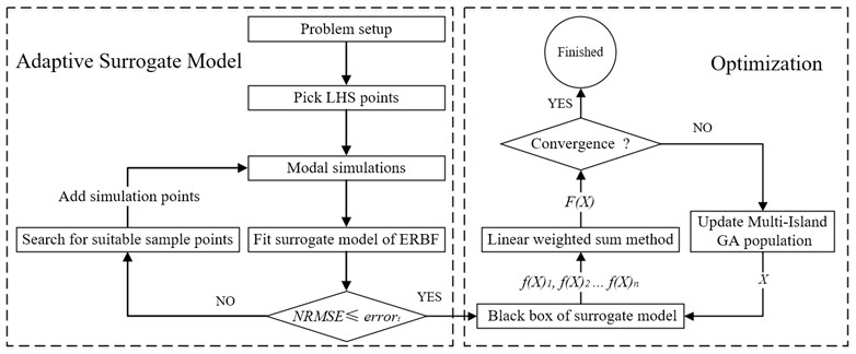
The Multi-Island GA method is combined with an adaptive surrogate modeling approach to achieve an excellent structure modal optimization process. The flow chart of the structure modal optimization approach is shown in Fig. 1. The original sampling points for the ERBF surrogate model building is picked using the LHS technique. The original sampling points is used for modal simulations, and the result of modal simulations is used to fit the surrogate model of ERBF. Standard error measure as convergence criteria to judge whether the iteration is converged or not, fit black box of surrogate model if the convergence condition is satisfied. Otherwise, new points are searched using adaptive sampling technique and added to the modal simulations. The black box of surrogate model is used to find the response in the structure modal optimization. For the multi-objective optimization problem, linear weighted sum method is employed as follows:
Go to finished if the iteration is converged, otherwise, update the Multi-Island GA population.
Fig. 1Flow chart showing the structure modal optimization process
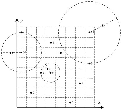
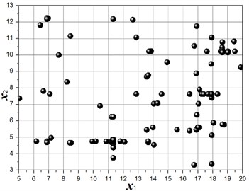
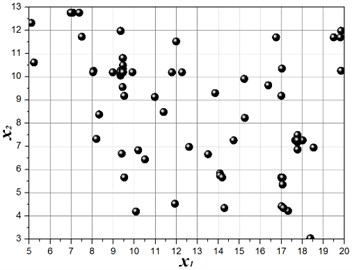
Uniform distribution of sampling points is a requirement in order to increase the precision of surrogate model [16]. The approach of adding new sample suitable points is proposed in this research. This approach is illustrated by a sampling case of two design variables. Points from 1 to 8 are the initial sampling points, and the new points 9, 10 and 11 are ready to add to the modal simulations in Fig. 2. Before adding to the modal simulation, the Euclidean distance is evaluated between new points and selected sampling points. The values of , and are the smallest Euclidean distances between point 9, 10 and 11 to all selected points, respectively. Point 11 is chosen because the value of is maximum compare with and . Graph traversal search algorithm is used in the selection of new sampling points. With this adaptive sampling approach, the most appropriate sample points are chosen to improve the precision of the surrogate model.
Fig. 2Add new sampling points
3. Structure modal optimization of strapdown inertial navigation system
In order to avoid strapdown inertial navigation system resonance, and make the helicopter flies safely. Structure modal optimization of strapdown inertial navigation system is very important. In this section, modal analysis of the strapdown inertial navigation system is performed using FEA, and structure modal optimization of strapdown inertial navigation system for an electric helicopter is studied using the adaptive surrogate model and Multi-Island GA algorithm.
3.1. Structure of strapdown inertial navigation system
The strapdown inertial navigation system is composed of damping material, copper metal and inertial navigation sensor. Impression drawing of the strapdown inertial navigation system is shown in Fig. 3.
Fig. 3Impression drawing of the strapdown inertial navigation system
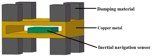
There is a fixed connection between damping material and copper metal as same as the connection between copper metal and inertial navigation sensor. Material properties of the three parts are shown in Table 2. The modal frequencies of the strapdown inertial navigation system are discussed only in this paper, so the damping factor is not listed in Table 2.
Table 2Material properties of strapdown inertial navigation system
Material | Density | Yong’s modulus (Pa) | Poisson’s ratio |
Vibration damping material | 16 kg/m-3 | 9.9E+4 | 0.45 |
Copper metal material | 8300 kg/m-3 | 1.1E+11 | 0.34 |
Inertial navigation sensor | 2770 kg/m-3 | 7.1E+10 | 0.33 |
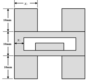
Geometrical parameters of the strapdown inertial navigation system are shown in Fig. 4. The parameters of and are design variables. The shape of damping material and copper metal is both square from top view, and the copper metal is symmetrical about the horizontal center section.
Fig. 4Geometrical parameters of the strapdown inertial navigation system
3.2. Problem setup
The strapdown inertial navigation system is installed in the flight control box. The flight control box is installed on the helicopter. Flexible modes are considered only. The translation and rotation of rigid modes are not considered. In this paper, modal frequencies from mode 1 to mode 6 are considered only. There are six objective functions (, , , , , ) in this structure modal optimization problem. According to the characteristic of the six response values, the structure modal optimization problems in this paper have more than one optimum solution. For this multi-objective structure modal optimization problem, linear weighted sum method is employed as follows:
where the sub-objective function defined as:
The design variable , is the value of mode , is an arbitrary integer. In this study, the helicopter is a coaxial twin rotor helicopter. The rotor is driven directly by the electric motor and not through the gearbox. In order to make the helicopter control decoupling easy, electronic speed regulator is used to control the electric motor at fixed rotation speed. Other researchers in our group find that the efficiency of the rotor is most high at 480 rpm. So, the value of equal to 8 Hz. The multi-objective functions are to maximize the difference between the natural frequencies and the excitation frequency:
Subjected to the geometry constraints:
The measurements of the inertial navigation sensor are 15 mm for length and width, and 3 mm for height. In order to ensure every damping material is separate. The minimum value of is equal to 5. And the length and width of damping material cannot be too small to support the counterweight steady, the maximum value of is equal to 5. The space in the flight control box is limited. In order to maximize the variation range of the counterweight weight. The value of is between 3 and 13.
3.3. Results
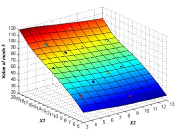
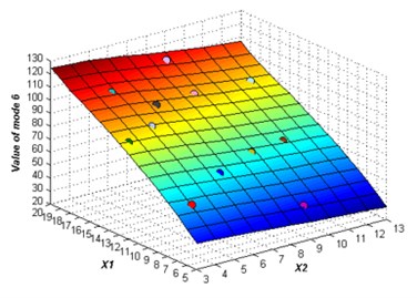
The initial sampling points are required to build the ERBF surrogate model is selected using LHS approach. The whole number of 15 training points are picked to build the original surrogate model. The adaptive algorithm is able to check the accuracy of the surrogate model by comparing the value of NRMSE, and request for additional sampling points whenever necessary. At 2 % confidence bounds the adaptive algorithm requested a supernumerary two sampling points to improve the accuracy of the ERBF surrogate model. The confidence bound of 2 % is satisfied using total sampling points of 17. The responses of the adaptive surrogate model from mode 1 to mode 6 are shown in Fig. 5. The points on the response surfaces are the numerical solution of FEA. The values of numerical solution and the values of response of the adaptive surrogate model are equal basically as showed in Fig. 5.
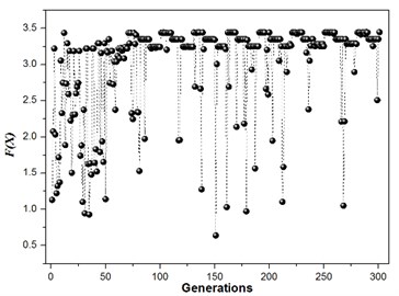
The selection of the weights for the multi-objective functions will have a greater effect on the final optimum modal frequencies since the weights will decide where location the optimum modal frequencies falls on [17]. Structure modal optimization is studied using different weights. Three groups of weights are chosen to optimize the modal of the strapdown inertial navigation system in this paper. The structure modal optimization history for the multi-objective function with a degressive weights ( 6, 5, 4, 3, 2, 1) is illustrated in Fig. 6.
Fig. 5The responses of the adaptive surrogate model
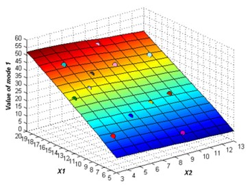
a)
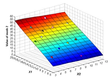
b)
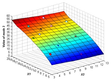
c)
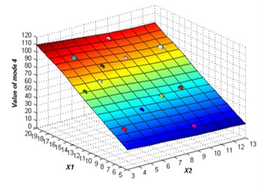
d)
e)
f)
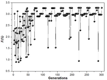
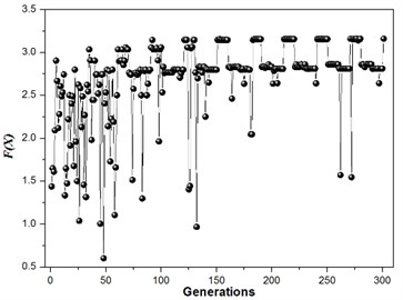
The structure modal optimization history shows the increase of . The number of islands is equal to 3 in Multi-Islands GA algorithm, since there is three locally optimal solution. But the globally optimal solution only has one, the value equal to 3.45, and the structure size parameters and modal values is shown in Table 3. The structure modal optimization history for the multi-objective function with an equal weights ( 1) is shown in Fig. 7. The structure modal optimization history shows the globally optimal solution far away from the other two locally optimal solution compare with multi-objective function with degressive weights. The value of globally optimal solution equal to 3.28, and structure size parameters and modal values are shown in Table 4. The structure modal optimization history with the multi-objective function with an incremental weights ( 1, 2, 3, 4, 5, 6) is shown in Fig. 8. The structure modal optimization history shows the globally optimal solution is more small compare with multi-objective function with degressive weights and equal weights. The value of globally optimal solution equal to 3.16, and structure size parameters and modal values are shown in Table 5.
Fig. 6Structure modal optimization history, w1= 6, w2= 5, w3= 4, w4= 3, w5= 2, w6= 1, 2 % NRMSE
a)
b)
Fig. 7Structure modal optimization history, w1= 1, w2= 1, w3= 1, w4= 1, w5= 1, w6= 1, 2 % NRMSE
a)
b)
Table 3Structure parameter and modal value, w1= 6, w2= 5, w3= 4, w4= 3, w5= 2, w6= 1, 2% NRMSE
(mm) | (mm) | (Hz) | (Hz) | (Hz) | (Hz) | (Hz) | (Hz) | |
17.93 | 7.64 | 44.02 | 44.12 | 44.41 | 91.97 | 95.40 | 105.6 | 3.45 |
Table 4Structure parameter and modal value, w1= 1, w2= 1, w3= 1, w4= 1, w5= 1, w6= 1, 2 % NRMSE
(mm) | (mm) | (Hz) | (Hz) | (Hz) | (Hz) | (Hz) | (Hz) | |
9.46 | 10.19 | 19.99 | 19.99 | 25.68 | 43.75 | 53.27 | 60.46 | 3.28 |
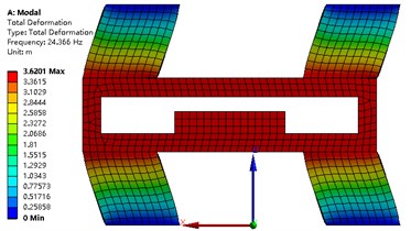
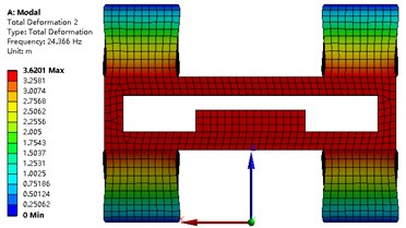
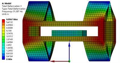
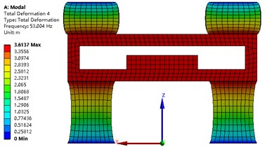
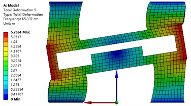
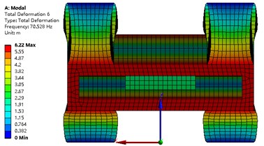
The modal analysis of the strapdown inertial navigation system is studied by FEA method. ANSYS software is used in this research. The finite element mesh is hexahedral. The vibration shape and frequency of the strapdown inertial navigation system are studied only in this research, so the type of modal analysis is simplified as no damping. Non-linear analysis is not to be considered in this paper. The modal analysis type of the strapdown inertial navigation system is linear. The subspace solver allows the user to take advantage of a distributed architecture to perform faster computations. So, the subspace is selected as the analysis type. The tolerance type is slider, and the tolerance value equal to 1.6e-4 meter. The damping material does not contribute to the vibration shape and frequency, but it is an important role that the energy of the vibration is weakened. The upper and under boundary of vibration damping material is fixed in this research. Results of modal with primary structure parameter for the strapdown inertial navigation system is shown in Fig. 9. Inertial navigation sensor is moved back and forth in -axis for mode 1, and -axis for mode 2, and -axis for mode 4. Inertial navigation sensor is rotated around -axis for mode 3, and -axis for mode 5, and -axis for mode 6.
Fig. 8Structure modal optimization history, w1= 1, w2= 2, w3= 3, w4= 4, w5= 5, w6= 6, 2 % NRMSE
a)
b)
The values of natural frequency from mode 1 to mode 6 are 24.37 Hz, 24.37 Hz, 31.31 Hz, 53.00 Hz, 65.34 Hz, 70.53 Hz, respectively. Since the value of is obtained from Eq. (26), and the results are shown in Table 6. The value of object function of structure modal optimization is big than the primary, it means the natural frequency of structure modal optimization is more far away from the excitation frequency compare with the primary.
Table 5Structure parameter and modal value, w1= 1, w2= 2, w3= 3, w4= 4, w5= 5, w6= 6, 2 % NRMSE
(mm) | (mm) | (Hz) | (Hz) | (Hz) | (Hz) | (Hz) | (Hz) | |
18.64 | 12.08 | 42.10 | 42.51 | 42.85 | 90.09 | 92.28 | 100.04 | 3.16 |
Table 6Structure modal optimization results compare with primary results
Primary | Optimization | |
Degressive | 0.95 | 3.45 |
Equal | 1.21 | 3.28 |
Incremental | 1.46 | 3.16 |
4. Time- and frequency-domain analysis of strapdown inertial navigation system structure
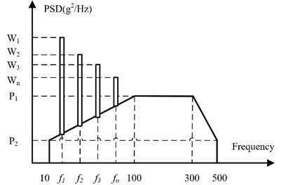
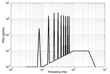
The harmonic vibration of the helicopter can be predicted under the condition of fixed rotor speed compare to the uncertainty of the vibration due to mechanical imbalance. The apparent periodicity is the characteristic of the harmonic vibration of helicopter. The vibration environment of the helicopter includes harmonic vibration and random vibration [18]. The excitation spectrum of helicopter is shown in Fig. 10.
From the Chapter 4 of Helicopter Aerodynamics Manual [18], the and is equal to 0.01 and 0.001, respectively. The peak acceleration of resonant frequency of , , , are shown in Table 7.
In this research, the optimization strapdown inertial navigation system structure of the equal weights and the primary strapdown inertial navigation system structure is used to research the time- and frequency-domain analysis. The 1th to 9th order resonant frequencies are considered because the maximum modal frequency is less than 72 Hz
Fig. 9Modal analysis of strapdown inertial navigation system
a)
b)
c)
d)
e)
f)
Fig. 10Power spectral density of the helicopter
4.1. Time-domain analysis of strapdown inertial navigation system structure
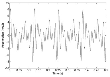
The harmonic vibration as sine waves and random vibration as excitations are used to research the time-domain characteristic. Since the number of helicopter blades is equal to 2, the 2th order harmonic phase is half a cycle longer than the 1th order harmonic [18, 19]. The th order resonant excitation is defined as follows:
The value of are shown in Table 7, the value of is equal to 8 Hz. The helicopter excitation is defined as:
The total excitation is show in Fig. 11. The random excitation is small compare to resonant excitation, so the total excitation is displayed as cyclical.
Table 7The peak acceleration of every resonant frequency
Resonant frequency (Hz) | Peak acceleration (m/s2) |
3-10 | 0.70/(10.70-) |
10-25 | 0.10× |
25-40 | 2.50 |
40-50 | 6.50-0.10× |
50-500 | 1.50 |
Fig. 11The total excitation of the helicopter
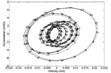
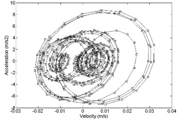
The time-domain analysis of the strapdown inertial navigation system structure is studied by FEA method. ANSYS software is used in this research. The finite element mesh is hexahedral. The damping ratio of the damping material is equal to 0.05. The time step is equal to 0.001 s. The step end time is equal to 0.5 s. In this research, the direction response and direction response is same basically. So, direction response and direction response is considered only. The comparison between primary and optimized structure with acceleration response and velocity response is shown in Fig. 12. It shows that the optimized convergence area of velocity response and the acceleration response is smaller than the primary.
Fig. 12Comparison of acceleration response and velocity response between a) primary and b) optimized structure, z direction
a)
b)
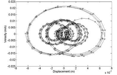
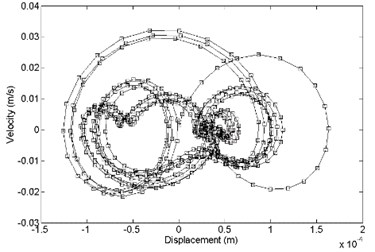
In the direction, the comparison between primary and optimized structure with displacement response and velocity response is shown in Fig. 13. It shows that the optimized convergence area of velocity response and the displacement response is smaller than the primary.
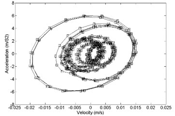
In the direction, the comparison between primary and optimized structure with acceleration response and velocity response is shown in Fig. 14. It shows that the optimized convergence area of velocity response and the acceleration response is smaller than the primary.
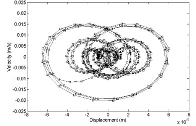
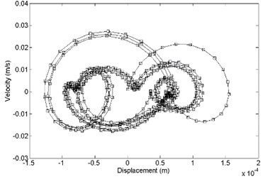
In the direction, the comparison between primary and optimized structure with displacement response and velocity response is shown in Fig. 15. It shows that the optimized convergence area of velocity response and the displacement response is smaller than the primary.
Fig. 13Comparison of displacement response and velocity response between a) primary and b) optimized structure, z direction
a)
b)
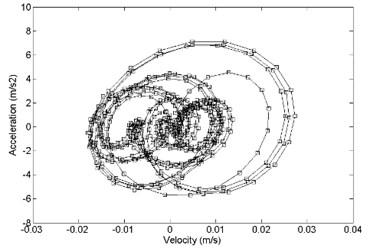
Fig. 14Comparison of acceleration response and velocity response between a) primary and b) optimized structure, x direction
a)
b)
Fig. 15Comparison of displacement response and velocity response between a) primary and b) optimized structure, x direction
a)
b)
4.2. Frequency-domain analysis of strapdown inertial navigation system structure
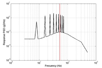
The frequency-domain analysis of the strapdown inertial navigation system structure is studied by FEA method. ANSYS software is used in this research. The finite element mesh is hexahedral. The damping ratio of the damping material is equal to 0.05. In this research, the direction response and direction response is same basically. So, direction response and direction response is considered only. From the power spectral density of the helicopter in Fig. 10, acceleration power spectral density is defined as Fig. 16.
Fig. 16Acceleration power spectral density
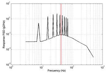
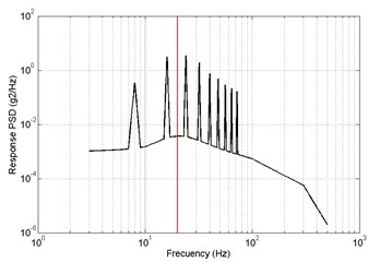
In direction, the response PSD of primary and optimized is shown in Fig. 17. The red lines are the 4th order modal frequency. It shows that the 4th order natural frequency of structure modal optimization is more far away from the excitation frequency compare with the primary. The value of response RMS of primary is big than optimized.
Fig. 17Results of frequency-domain analysis, primary a) RMS = 2.9087 m/s2, optimized b) RMS = 2.7811 m/s2, z direction
a)
b)
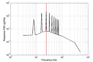
Fig. 18Results of frequency-domain analysis, primary a) RMS = 2.1217 m/s2, optimized b) RMS = 1.8873 m/s2, x direction
a)
b)
In direction, the response PSD of primary and optimized is shown in Fig. 18. The red lines are the 1th order modal frequency. It shows that the 1th order natural frequency of structure modal optimization is more far away from the excitation frequency compare with the primary. The value of response RMS of primary is big than optimized.
Results of time-domain analysis indicated that the optimized convergence area of velocity response and the acceleration response, and velocity response and the displacement response are smaller than the primary. Results of frequency-domain analysis indicated that 1th and 4th order natural frequency of structure modal optimization is more far away from the excitation frequency compare with the primary.
5. Conclusions
An adaptive surrogate model that new sampling points is located in blank area as the purpose is proposed using iteration sampling and ERBF in this paper. Multi objective structure modal optimization of strapdown inertial navigation system by considering six objectives.
Maximizing the difference between the natural frequency and excitation frequency was performed using Multi-Island GA algorithm. The executable of optimizing using the adaptive surrogate model in combination with Multi-Island GA optimization approach is demonstrated successfully.
It was observed that total of 15 LHS sampling points are picked to calculate the original ERBF surrogate model. The structure modal optimization presented in this paper required two sampling points for 2 % confidence bound.
The effect of the selection of different weights on the optimum modal frequencies is researched. For degressive weights, the value of object function is equal to 3.45, and 3.28, 3.16 is for Equal weights and Incremental weights. The structure modal optimization of the strapdown inertial navigation system is a useful method to avoid strapdown inertial navigation system resonance. Meanwhile, the adaptive surrogate model can be used to other engineering optimization problems, such as, aerodynamic optimization, stealth optimization.
Results of time- and frequency-domain analysis indicated that the optimized strapdown inertial navigation system structure has better vibration characteristics to the primary.
In the process of searching suitable sample points, the efficiency of graph traversal search algorithm is undesirable. In future works, some highly efficient algorithm will be used to solve this problem.
References
-
Liiva J. Unsteady aerodynamic and stall effects on helicopter rotor blade airfoil sections. Journal of Aircraft, Vol. 6, Issue 1, 1969, p. 46-51.
-
Zhang A. Zhou, et al. Helicopter Aerodynamics Manual. Chapter 2, China Aeronautical Industry Press, China, 1991.
-
Nemra A., Aouf N. Robust INS/GPS sensor fusion for UAV localization using SDRE nonlinear filtering. IEEE Sensors Journal, Vol. 10, Issue 4, 2010, p. 789-798.
-
Lahham J. I., Wigent D. J., Coleman A. L. Tuned support structure for structure-borne noise reduction of inertial navigator with dithered ring laser gyros (RLG). Position Location and Navigation Symposium, 2000.
-
Zhou Hui T., De Wen Hu, Ru Hua Li, et al. Damping design of strapdown inertial navigation system. Journal of Chinese Inertial Technology, Vol. 17, Issue 6, 2009, p. 648-650.
-
Wu Z., Huang D., Wang W., et al. Optimization for fire performance of ultra-low density fiberboards using response surface Methodology. BioResources, Vol. 12, Issue 2, 2017, p. 3790-3800.
-
Sun Z. G., Xiao S. D., Xu M. H., et al. Optimization of the structure of water axial piston pump and cavitation of plunger cavity based on the Kriging model. Journal of Vibroengineering, Vol. 18, Issue 4, 2016, p. 2460‑2474.
-
Akhtar T., Shoemaker C. A. Multi objective optimization of computationally expensive multi-modal functions with RBF surrogates and multi-rule selection. Journal of Global Optimization, Vol. 64, Issue 1, 2016, p. 17-32.
-
Mullur A. A., Messac A. Extended radial basis functions: more flexible and effective metamodeling. AIAA Journal, Vol. 43, Issue 6, 2005, p. 1306-1315.
-
Chen Z., Qiu H., Gao L., et al. A local adaptive sampling method for reliability-based design optimization using Kriging model. Structural and Multidisciplinary Optimization, Vol. 49, Issue 3, 2014, p. 401-416.
-
Remondo D., Srinivasan R., Nicola V. F., et al. Adaptive importance sampling for performance evaluation and parameter optimization of communication systems. IEEE Transactions on Communications, Vol. 48, Issue 4, 2000, p. 557-565.
-
Li T. M., Wu Y. T., Chuang Y. Y. Sure-based optimization for adaptive sampling and reconstruction. ACM Transactions on Graphics, Vol. 31, Issue 6, 2012, p. 1-9.
-
Vytla V. V. S., Huang P., Penmetsa R. Multi-objective aerodynamic shape optimization of high speed train nose using adaptive surrogate model. AIAA Applied Aerodynamics Conference, 2010.
-
Golzari A., Sefat M. H., Jamshidi S. Development of an adaptive surrogate model for production optimization. Journal of Petroleum Science and Engineering, Vol. 133, Issue 6, 2015, p. 677-688.
-
Zhang J. J., Xu L. W., Gao R. Z. Multi-island genetic algorithm optimization of suspension system. Telkomnika Indonesian Journal of Electrical Engineering, Vol. 10, Issue 7, 2012, p. 1685-1691.
-
Peng Fei Wu, Zan Z., Yi Z., et al. Influence of sampling point distribution in freeform surfaces fitting with radial based function model. Optics and Precision Engineering, Vol. 24, Issue 7, 2016, p. 1564-1572.
-
Alba E. Optimization Techniques for Solving Complex Problems. Parallel and Distributed Computing. Willey, 2008.
-
Jiang X. T., et al. Helicopter Aerodynamics Manual. Chapter 4, China Aeronautical Industry Press, China. 2005.
-
Deng S., Percin M., van Oudheusden B. W., Bijl H., Remes B, Xiao T. Numerical simulation of a flexible X-wing flapping-wing micro air vehicle. AIAA Journal, Vol. 55, Issue 7, 2017, p. 2295-2306.
About this article

