Abstract
In order to improve the strength and stability of the rotating support platform, modal and stress characteristics were simulated and calculated based on finite element analysis method. In Hypemesh, the model of the rotating support platform was established. In Abaqus, boundary conditions and loads were defined, and the natural frequencies and vibration modes of the first four orders were obtained. Based on the structure and stress characteristics of the crossbeam, different damping technologies were compared and analyzed, and rubber damping scheme was selected and designed. Through time mileage analysis, the load response and damping effect of damping scheme were verified. The results show that the rubber damping scheme can reduce the maximum stress by more than 15 % without changing the natural frequency substantially.
Highlights
- In order to improve the strength and stability of the rotating support platform, modal and stress characteristics were simulated and calculated based on finite element analysis method.
- In Abaqus, boundary conditions and loads were defined, and the natural frequencies and vibration modes of the first four orders were obtained.
- Based on the structure and stress characteristics of the crossbeam, different damping technologies were compared and analyzed, and rubber damping scheme was selected and designed.
1. Introduction
As an important equipment in the production and transportation of different industries, the rotating support platform can smoothly transmit the speed and torque output by the motor to the supported equipment, completing oscillation, mixing and other tasks. During the process, it is subjected to significant dynamic loads, which have a huge impact on its working stability [1]. Taking the rotating support platform of a concrete mixer truck as an example, during transportation, the planetary gear reducer needs to adjust the concrete mixing drum to maintain continuous rotation and mixing, to avoid concrete compaction or segregation due to insufficient mixing during transportation, which may affect the use of the construction site [2]. When the mixing system starts and stops without load or when concrete is loaded into the mixing drum, the reducer will generate a significant impact load due to the weight of the mixing drum or the weight of the concrete. During the transportation of concrete, braking and downhill operations can also generate significant inertial forces, causing significant axial and radial impacts on the support platform, resulting in noise and vibration during operation, affecting the accuracy of related transmission and reducing service life [3, 4]. Therefore, it is necessary to conduct modal analysis and vibration response calculation on the designed rotating support platform to ensure its reliability and stability in operation. With the development and popularization of computer technology, finite element method has rapidly become a widely used numerical analysis method [5]. Computer aided engineering has emerged as an indispensable part of the product design process [6]. After years of engineering application, CAE software has been widely used in industries such as electronics, shipbuilding, aviation, aerospace, machinery, construction, and automotive, with broad development prospects. ABAQUS is a finite element software that excels in solving complex nonlinear problems and is considered the most powerful finite element software. It can solve complex dynamic problems and simulate various complex materials such as composite materials and reinforced concrete in terms of large and complex problems and high nonlinearity. ABAQUS/CAE is a human-computer interaction interface that uses ABAQUS software for analysis and solving. The integrated environment includes capabilities such as model building, task submission, and result evaluation. Therefore, it is applied to simulate and analyze the modal characteristics of the rotating support platform.
2. Finite element simulation and analysis of modal characteristics
2.1. Establishment of the model
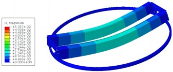
In HyperMesh, finite element models are established, mainly including creating material properties, element types, cross-sections, geometric models, and meshing. Due to the complexity of the actual structure of the model, simplification and equivalent processing are carried out in the finite element model. The main principle of simplification is to only retain its overall load-bearing structure. The main component material of the model is Q345, and its elastic modulus is set to 2.06e5 MPa, Poisson's ratio is set to 0.3. To ensure that the quality of the model in the finite element method is equal to the actual quality, increase the density of the tracks on the main beam. The finite element model mainly uses beam elements, mass point elements, and TRUSS elements, while the suspension structure is simulated using mass point elements. The steel wire rope is simulated using the specialized rope element TURSS in ABAQUS, but it is equivalent to a rod element in spectral analysis. In HyperMesh, points and lines are established based on actual structural dimensions and positions. Place different components in different components to easily modify certain components and section properties in the later stage. When dividing the grid, the grid and geometric dimensions will be placed in the same component, and the appropriate grid size will be entered. Through finite element mesh partitioning, it was found that the model has a total of 6016 nodes and 3396 elements, as shown in Fig. 1. Set the load to the maximum working load and couple stress with modal analysis.
Fig. 1Preprocessing of the model
a) Node model
b) Mesh model
HyperMesh provides rigid commands for nodes that experience coupling constraints, enabling “one-to-one” or “one to many” node coupling constraints. Rigid connections or hinges can be achieved by modifying the degrees of freedom of coupling constraints, such as the connection between the main beam and the track, the connection between the lifting block and the steel wire rope, the connection between the main beam and the end beam, and the connection between the ring beam and the ring rail. In other words, all degrees of freedom are constrained.
2.2. Result analysis
Preprocess the finite element model of the nuclear ring suspension in HyperMesh and export the inp file to ABAQUS for modal and spectral analysis. The solvers used for modal analysis in ABAQUS are divided into Lanczos, Subspace, and AMS. The commonly used solvers are Lanczos and subspaces, which use the generalized Jacobi iterative algorithm. This algorithm requires the use of a complete stiffness and mass matrix, resulting in high accuracy but slow calculation speed. Lanczos uses a set of vectors to achieve recursive computation, which, like subspace solvers, has high accuracy but faster speed. Therefore, modal analysis uses the Lanczos solver.
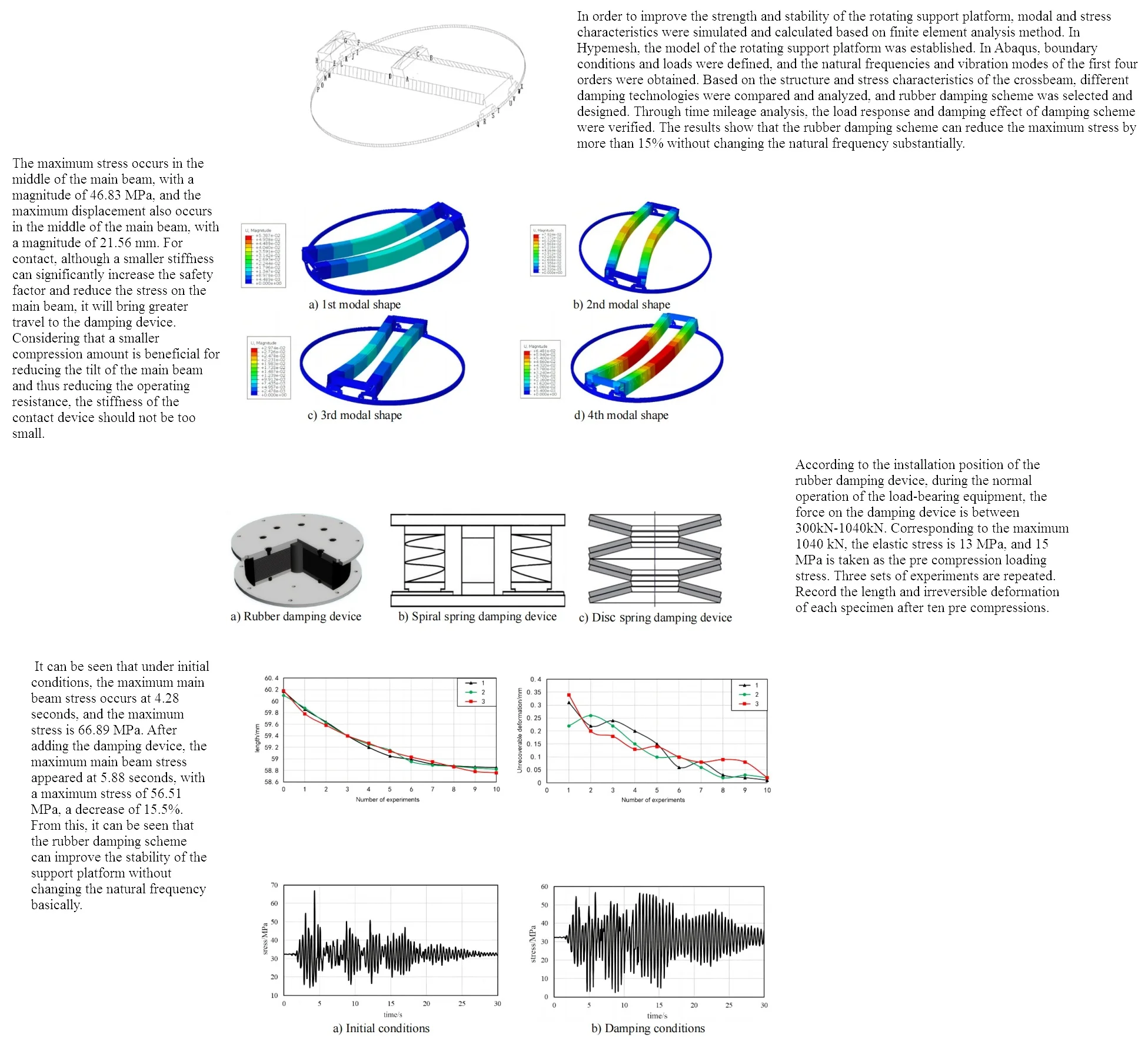
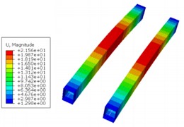
Through continuous iterative operations, the first four vibration forms of the rotating bracket can be obtained as shown in Fig. 2, with corresponding natural frequencies of 2.52 Hz, 3.67 Hz, 3.96 Hz, and 12.25 Hz, respectively. According to the above modal analysis results, it can be seen that the rotating bracket will generate periodic vibration during use. When the natural frequency is consistent with the excitation frequency of the external transmission system, it will cause resonance in the main beam structure, reduce the smoothness of the transmission, and even shorten the service life. The vibration response at the center of the supporting beam is the strongest, so the center can be reinforced, and the edge can be reduced in structural optimization.
Fig. 2The first four modal shapes
a) 1st modal shape
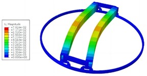
b) 2nd modal shape
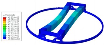
c) 3rd modal shape
d) 4th modal shape
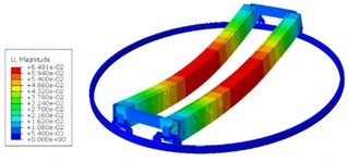
The main beam is the main load-bearing component of the nuclear ring crane structure, and its stress is an important factor affecting the seismic performance of the nuclear ring crane. The stress and displacement cloud map obtained through simulation is shown in Fig. 3. The maximum stress occurs in the middle of the main beam, with a magnitude of 46.83 MPa, and the maximum displacement also occurs in the middle of the main beam, with a magnitude of 21.56 mm. For contact, although a smaller stiffness can significantly increase the safety factor and reduce the stress on the main beam, it will bring greater travel to the damping device. Considering that a smaller compression amount is beneficial for reducing the tilt of the main beam and thus reducing the operating resistance, the stiffness of the contact device should not be too small.
Fig. 3Load response results
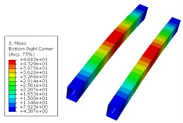
a) Stress simulation
b) Displacement simulation
3. Design and analysis of vibration reduction
3.1. Comparison of contact vibration reduction schemes
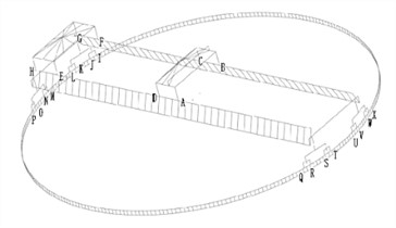
According to the structural characteristics of the rotating platform, three vibration reduction schemes have been proposed, including rubber damping devices, sliding damping devices, and spring damping devices. The rubber damping device is formed by alternating layers of steel plate and rubber, as shown in Fig. 4(a). It would be added between the structure and the ground, which is a soft connection that can filter most of the energy. Rubber itself has high elasticity, and the vertical stiffness of designed shock absorber is too small. In large-scale engineering structures, the bearing capacity is also insufficient. However, in general, soft steel plates are added inside rubber shock absorber to increase vertical stiffness and bearing capacity. The friction sliding damping device is a sliding surface set up in the upper and lower parts of the structure, and the upper part of the structure will slide horizontally relative to the lower part, reducing the effect of vibration on the upper structure. Friction can consume seismic energy and achieve cushioning effects. The friction sliding damping device has a simple, stable and reliable structure, and does not need to consider the issue of excessive intensity in actual vibration. That is, after adopting this structure, the impact of excessive intensity changes on the structure is relatively small. In addition, due to the presence of slip surfaces, this structure can also avoid resonance caused by the similarity between the natural frequency and seismic frequency of the structure. Spring damping devices are the most common damping devices, which are divided into spiral and disc types, as shown in Fig. 4(b) and Fig. 4(c). During vibration, they can use elastic deformation to convert vibration energy into elastic potential energy, thereby reducing the seismic force on the upper structure. Spiral springs have smaller bearing capacity and stiffness, and are not suitable for large engineering structures such as nuclear ring cranes. Disc springs have the characteristics of generating large loads with small deformations, and are not prone to aging or creep, making them suitable for large engineering structures. According to the analysis, the sliding damping device cannot achieve horizontal vibration reduction, and the size deviation of the spring damping device is large, which is not conducive to stability. Therefore, rubber damping devices were adopted to verify the damping effect through testing.
Fig. 4Different damping devices
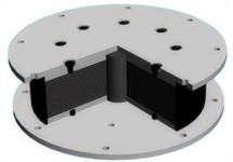
a) Rubber damping device
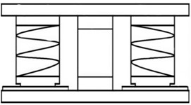
b) Spiral spring damping device
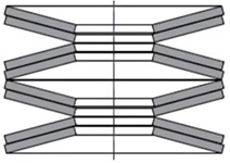
c) Disc spring damping device
3.2. Performance testing
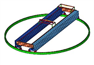
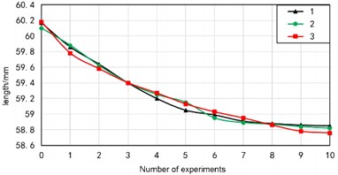
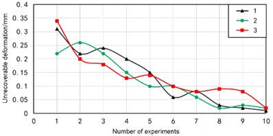
Based on a universal testing machine, the performance of rubber shock absorbers can be effectively tested. The applied pressure and displacement of the upper clamp can be recorded in real-time by a computer. By inputting the diameter and shape of the experimental material into the microcomputer of the universal testing machine, the area can be calculated. So real-time stress can be output, and strain can be output from the displacement of the clamp. The universal testing machine can output force displacement curves and stress-strain curves to calculate the compressive modulus of elasticity and compressive strength. Due to the inability to directly measure lateral strain, height and diameter size changes are measured to calculate Poisson’s ratio. According to the installation position of the rubber damping device, during the normal operation of the load-bearing equipment, the force on the damping device is between 300 kN-1040 kN. Corresponding to the maximum 1040 kN, the elastic stress is 13 MPa, and 15 MPa is taken as the pre compression loading stress. Three sets of experiments are repeated. Record the length and irreversible deformation of each specimen after ten pre compressions. The length change value is shown in Fig. 6, and the irreversible deformation curve is shown in Fig. 5.
During the eighth experiment, the length of the specimen remained largely unchanged before and after the experiment, and the irreversible deformation remained stable within 0.1 mm. The irreversible deformation in the tenth experiment is within 0.01 mm-0.02 mm, accounting for 0.02 % of the total length and can be ignored. After the pre compression experiment, the length of the specimen changed to 98 % of the original length, so the original length needs to be increased by about 2 % compared to the used length. After ten pre compressions, the irreversible deformation can be basically ignored, and the performance is relatively stable, but the length of the elastic block becomes 98 % of the original. So when designing calculations, the original length needs to be increased by about 2 % compared to the used length. After pre compression experiments, it was found that the compressive strength of the material was greater than 34 MPa, the elastic modulus was about 250 MPa, and the Poisson's ratio was 0.46.
Fig. 5The curve of pressure over time
3.3. Vibration comparison
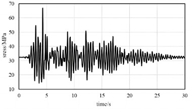
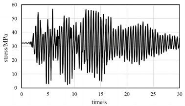
The variation of stress can effectively reflect the vibration response. When using the time history analysis method to analyze the vibration reduction response, damping needs to be defined. In ABAQUS, Rayleigh damping, structural damping, and direct modal damping can be defined. Among them, Rayleigh damping is the most widely used in engineering applications and the calculation is simple, so Rayleigh damping is used. Time history analysis methods can be divided into explicit algorithms and implicit algorithms. Display algorithms are used to analyze highly linear problems, while implicit algorithms are designed for general nonlinear problems. The time history analysis method uses implicit algorithms and is divided into two analysis steps, including static analysis and time history analysis. Compare the load response results before and after vibration reduction, as shown in Fig. 6. It can be seen that under initial conditions, the maximum main beam stress occurs at 4.28 seconds, and the maximum stress is 66.89 MPa. After adding the damping device, the maximum main beam stress appeared at 5.88 seconds, with a maximum stress of 56.51 MPa, a decrease of 15.5 %. From this, it can be seen that the rubber damping scheme can improve the stability of the support platform without changing the natural frequency basically.
Fig. 6Stress response comparison
a) Initial conditions
b) Damping conditions
4. Conclusions
There is a significant inertial force during the operation of the rotating support platform. If the vibration reduction performance is insufficient, it will have a significant axial and radial impact on the support platform, reducing work stability. The rigid-flexible coupling of the rotating support platform model was established based on HyperMesh. By utilizing the one-to-many nodes coupling constraint, the support beam model can exhibit flexibility, enabling synchronous calculation of modal response and stress response. In addition, this can also avoid problems such as non-convergence or too long calculation time during the simulation calculation. A rubber shock absorber was added for comparative analysis of load response results, and the following conclusions can be drawn.
1) The vibration reduction scheme based on rubber damping can effectively reduce the measured maximum stress by more than 15 %. This approach can achieve optimization of load response at lower cost conditions.
2) The finite element method is very effective for modal and dynamic response analysis of various complex support equipment, and can significantly improve product performance under low-cost conditions.
References
-
A. Daşdemir, “A modal analysis of forced vibration of a piezoelectric plate with initial stress by the finite-element simulation,” Mechanics of Composite Materials, Vol. 58, No. 1, pp. 69–80, Mar. 2022, https://doi.org/10.1007/s11029-022-10012-7
-
Z. Zhang, P. Liu, and C. Li, “A shallow cable with a tuned mass-high damping rubber damper,” Journal of Low Frequency Noise, Vibration and Active Control, Vol. 42, No. 1, pp. 392–402, Sep. 2022, https://doi.org/10.1177/14613484221130330
-
V. Nicoletti, R. Martini, L. Amico, S. Carbonari, and F. Gara, “Operational modal analysis for supporting the retrofit design of bridges,” Ce/papers, Vol. 6, No. 5, pp. 1182–1188, Sep. 2023, https://doi.org/10.1002/cepa.2125
-
M. Sohrabifard, M. Nategh, and M. Ghazavi, “Evaluation, calibration, and modal analysis for determination of contact stiffness between workpiece and components of milling fixture,” Proceedings of the Institution of Mechanical Engineers, Part B: Journal of Engineering Manufacture, Vol. 237, No. 12, pp. 1819–1835, Nov. 2022, https://doi.org/10.1177/09544054221138165
-
T. You, J. Zhou, D. J. Thompson, D. Gong, J. Chen, and Y. Sun, “Vibration reduction of a high-speed train floor using multiple dynamic vibration absorbers,” Vehicle System Dynamics, Vol. 60, No. 9, pp. 2919–2940, Sep. 2022, https://doi.org/10.1080/00423114.2021.1928248
-
R. Darleux, B. Lossouarn, I. Giorgio, F. Dell’Isola, and J.-F. Deü, “Electrical analogs of curved beams and application to piezoelectric network damping,” Mathematics and Mechanics of Solids, Vol. 27, No. 4, pp. 578–601, Jul. 2021, https://doi.org/10.1177/10812865211027622
About this article

The paper is supported by funding project with the number of 2021XJ24.
The datasets generated during and/or analyzed during the current study are available from the corresponding author on reasonable request.
The authors declare that they have no conflict of interest.
