Abstract
In order to ensure the safety and stability of the oil tank in the transportation process, the dynamic response of the tank body was simulated, tested and optimized based on the finite element method and vibration testing technology. The modal vibration modes were calculated respectively under the conditions of 50 %, 75 % and 100 % liquid filling of the oil tank, and the influence of the oil content on the overall structure mode was obtained. Under the full load condition, the stress response under continuous and non-continuous impact loads was calculated. Based on the analysis results, the vibration damping elements were arranged, and the optimization effect of vibration reduction was verified and analyzed by vibration testing. The results show that full load is more conducive to the stability of the oil tank, and the vibration damping element can reduce the maximum amplitude by more than 80 %, which has good economic and social benefits.
Highlights
- In order to ensure the safety and stability of the oil tank in the transportation process, the dynamic response of the tank body was simulated, tested and optimized based on the finite element method and vibration testing technology.
- The modal vibration modes were calculated respectively under the conditions of 50%, 75% and 100% liquid filling of the oil tank, and the influence of the oil content on the overall structure mode was obtained.
- Based on the analysis results, the vibration damping elements were arranged, and the optimization effect of vibration reduction was verified and analyzed by vibration testing.
1. Introduction
Tank truck is a common transportation vehicle. When driving on the road, the tank will vibrate due to the uneven road or emergency braking [1]. When the vibration frequency caused by external conditions is close to the natural frequency of the tank itself, there will be resonance phenomenon, resulting in the structural damage of the tank, and even cause the rollover of the tank, causing irreparable casualties and huge property losses [2]. Therefore, it is very necessary to study the mode and vibration response of the tank. Modal analysis can obtain the inherent vibration characteristics of mechanical structures, each mode has a specific natural frequency and the corresponding mode shape [3,4]. Therefore, in industrial design, modal analysis is usually used to study the dynamic performance of object structures. The significance of modal analysis lies in its ability to calculate the resonance region of object structures, thus providing guidance for the design of structures. In addition, it can also serve as the basis for other dynamic characteristics analysis, providing a basis for the structural dynamic characteristics, vibration characteristics and vibration fault diagnosis of structural systems, so as to optimize the design. In addition to considering the strength, vibration failure is usually also used as the main failure mode of the tank body of the semi-trailer for cryogenic liquid transportation in actual operation [5, 6]. In the process of product inspection, vibration tests are carried out to simulate the vibration response of the tank body of the semi-trailer for cryogenic liquid transportation under the driving conditions. In addition to verifying the durability of the piping system and support structure, it is also necessary to verify whether the tank structure resonates within the range of road excitation frequency. Therefore, the study of the dynamic response, resonance frequency and mode characteristics of the tank body is of great significance for further lightweight design of the tank structure and avoiding the damage caused by resonance.
2. Simulation and analysis of modal characteristics
2.1. Model establishment and analysis
The tank model of the tanker is established by Workbench. The upper part of the model is divided into the tank body, and the lower part is divided into the bracket. The tank material is set as Q235 steel in the database, with a density of 7850 kg/m3, an elastic modulus of 206 GPa, and a Poisson's ratio of 0.3. Modal analysis is carried out on the no-load tank body. The no-load tank body is not affected by the oil body, so only the Modal module is needed. In the Modal module, a fixed constraint is set for the bracket of the tank body, and the gravity acceleration is set for the system. When analyzing the liquid-filled tank, the oil body is regarded as a medium and the influence of its damping on the system is ignored. The Modal Acoustics module in the Workbench is called to conduct modal analysis on the liquid-filled tank. Different from the empty tank, the internal of the liquid-filled tank is also affected by the oil. In addition to setting the tank parameters as the empty tank in the database, the parameters of the oil liquid need to be set. The density of the oil liquid is set to 760 kg/m3 and the sound velocity is set to 1430 m/s. First, the internal of the tank is filled in Design Modeler and the filled body is set as a fluid domain. In Modal Acoustics, the fluid region is set as Acoustics Region and the surface of the fluid domain in the tank is set as a free liquid surface. The tank structure is set as Physics Region in order to automatically generate the fluid-solid coupling surface. Because the tank is fixed on the vehicle body, a fixed constraint needs to be added to the tank base. Considering the influence of gravity on the tank, the gravity acceleration is set to 9.81 m/s2.
2.2. Modal analysis under different working conditions
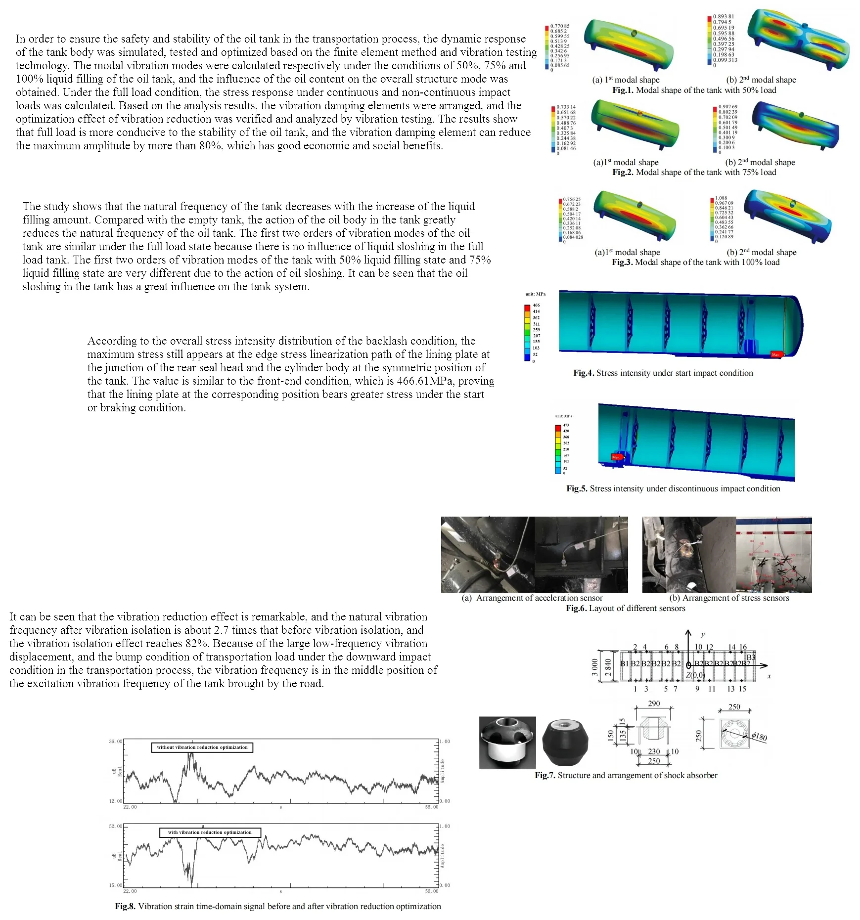
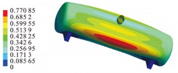
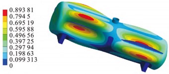
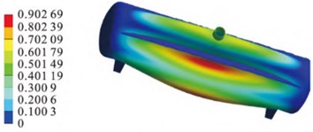
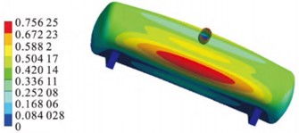
Since the whole system is considered to be undamped, the solution type needs to be set as unsymmetric before solving. The first six orders of natural frequencies of the fuel tank in the 50 %, 75 % and full load states are shown in Table 1. The first two orders of vibration modes under different working conditions are shown in Fig. 2, Fig. 3 and Fig. 4. The study shows that the natural frequency of the tank decreases with the increase of the liquid filling amount. Compared with the empty tank, the action of the oil body in the tank greatly reduces the natural frequency of the oil tank. The first two orders of vibration modes of the oil tank are similar under the full load state because there is no influence of liquid sloshing in the full load tank. The first two orders of vibration modes of the tank with 50 % liquid filling state and 75 % liquid filling state are very different due to the action of oil sloshing. It can be seen that the oil sloshing in the tank has a great influence on the tank system.
Table 1Comparison of optimization results
Load states | 1st order | 2nd order | 3rd order | 4th order | 5th order | 6th order |
Natural frequency / Hz | ||||||
50 % | 17.3 | 21.3 | 28.9 | 35.9 | 46.6 | 52.2 |
75 % | 14.3 | 19.5 | 24.4 | 37.7 | 42.3 | 47.8 |
100 % | 11.5 | 17.6 | 21.7 | 34.7 | 39.4 | 42.4 |
Fig. 1Modal shape of the tank with 50 % load
a) 1st modal shape
b) 2nd modal shape
Fig. 2Modal shape of the tank with 75 % load
a) 1st modal shape
b) 2nd modal shape
Fig. 3Modal shape of the tank with 100 % load
a) 1st modal shape
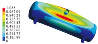
b) 2nd modal shape
2.3. Impact response under different working conditions
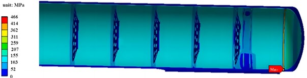
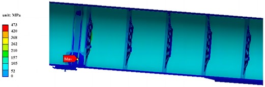
The stress intensity of the whole tank under emergency start condition is shown in Fig. 4. Set the path to evaluate the strength at the position of the whole high stress area. It can be seen that the maximum stress is still the connection position of the inner support ring plate. This is a discontinuity area of the structure, which runs through the thickness of the lining plate, and the strength is checked according to the stress threshold of the inner lining plate material. According to the overall stress intensity distribution of the backlash condition, the maximum stress still appears at the edge stress linearization path of the lining plate at the junction of the rear seal head and the cylinder body at the symmetric position of the tank. The value is similar to the front-end condition, which is 466.61 MPa, proving that the lining plate at the corresponding position bears greater stress under the start or braking condition.
Fig. 4Stress intensity under start impact condition
The overall stress strength of the mobile storage tank under the conditions of pits or protrusions and other bumps is shown in Fig. 5. It can be seen that the overall stress level is relatively high. The path evaluation strength is set at the location of the overall high stress area. Two stress linearization paths are selected for the downward impact condition, and they are checked according to the allowable stress strength of 1.5 times the primary local film stress strength limit of the structure. Because the overall maximum stress occurs at the bending of the content support reinforcing ring structure at the traction seat connected to the front part of the tank and the liquid transportation semi-trailer, the stress is relatively large. This shows that the vertical bumps of the downward impact condition have a greater impact on the stress of the content support reinforcing ring, and it can be seen that the strengthening ring and the lower support part are subjected to a relatively harsh stress environment. According to the combination of stress components and the allowable limit of stress strength, the downward impact condition is assessed as qualified. It can be seen that the conditions of pits or protrusions and other bumps have a greater impact on the stress of the support part, and the local stress level of the tank is relatively high.
Fig. 5Stress intensity under discontinuous impact condition
3. Parameter testing of road dynamic characteristics
3.1. Preparation for test analysis
In order to obtain the dynamic vibration and strain signals of the vibration and strain measuring points of the liquid transport semi-trailer when driving on a specific road surface and analyze the amplitude and frequency characteristics of the vibration and strain signals. According to the dynamic analysis results of the vibration and strain signals, combined with the test modal analysis and static strain size of the liquid transport semi-trailer structure, the influence of the low temperature liquid transport semi-trailer on the vibration-strain when driving on a specific road surface is comprehensively analyzed. The test object is the liquid transport semi-trailer product studied, and the tank is filled with nitrogen. The directions of vibration detection points are horizontal, vertical, and vertical directions of the semi-trailer for liquid transportation, as shown in Fig. 6(a). Static strain gauges were used as a road test tool for semitrailers for liquid transportation. The schematic diagram of the strain gauge assembly is shown in Fig. 6(b). The liquid transport semi-trailer completed the connection, debugging and setting of all sensors, strain gauges and testing instruments in a static state. According to the data acquisition channel and the actual test situation, the strain detection points were divided into four groups, vibration detection points were added to each group, and four road tests were repeated. The main road surfaces were divided into cement road, stone road and washboard road, which were used to simulate the failure of the transport tank car when it undergoes several unstable transport loads in the actual transport process.
Fig. 6Layout of different sensors
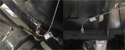
a) Arrangement of acceleration sensor
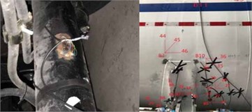
b) Arrangement of stress sensors
3.2. Vibration reduction design and result analysis
In order to further ensure the stability of the oil tank, a rubber damper is added as a vibration reduction unit. According to the simulation results of stress, its structure and arrangement are shown in Fig. 7. The vertical bearing capacity is 26 kN, and the vertical compression stiffness is 52 kN/cm.
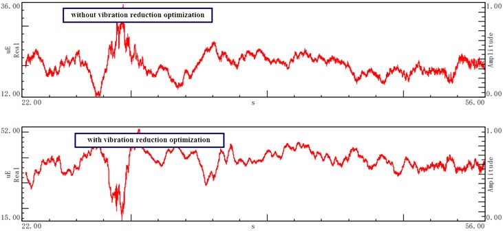
According to the force characteristics, 16 vertical rubber damper are arranged between the shelf. The vertical damper is welded and fixed to the transport vehicle plate through the steel box with openings. In order to avoid the collision of the tank body caused by the brake in the process of transportation, several horizontal shock absorbers are set between the vertical limit frame and the prefabricated components. According to the frequency spectrum analysis of vibration response of block and rock road, the vibration strain results before and after vibration reduction optimization are shown in Fig. 8. It can be seen that the vibration reduction effect is remarkable, and the natural vibration frequency after vibration isolation is about 2.7 times that before vibration isolation, and the vibration isolation effect reaches 82 %. Because of the large low-frequency vibration displacement, and the bump condition of transportation load under the downward impact condition in the transportation process, the vibration frequency is in the middle position of the excitation vibration frequency of the tank brought by the road.
Fig. 7Structure and arrangement of shock absorber
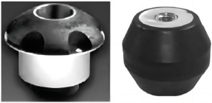
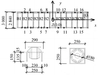
Fig. 8Vibration strain time-domain signal before and after vibration reduction optimization
4. Conclusions
1) The vibration mode of the tank body under different liquid filling conditions is different, which is caused by the liquid surface shaking of the tank body under the condition of not being filled with liquid. The oil body has a great influence on the inherent characteristics of the tank body of the oil tank car. With the increase of the liquid filling amount in the tank, the inherent frequency of the tank body of the oil tank car will decrease.
2) The vibration damping element applied works well. According to the random vibration analysis, the vibration isolation design can optimize the amplitude of about 80 %, and the vibration and loss reduction are obvious, which saves the cost and improves the economic benefits, and has a good application prospect.
References
-
S. de Carolis, A. Messina, and L. Soria, “Modal analysis through response-based FRFs: additional modes for local diagnoses,” Journal of Sound and Vibration, Vol. 549, No. 1, p. 117574, Apr. 2023, https://doi.org/10.1016/j.jsv.2023.117574
-
M. R. Zarastvand, M. H. Asadijafari, and R. Talebitooti, “Acoustic wave transmission characteristics of stiffened composite shell systems with double curvature,” Composite Structures, Vol. 292, No. 1, p. 115688, Jul. 2022, https://doi.org/10.1016/j.compstruct.2022.115688
-
R. Talebitooti, M. Zarastvand, and H. Darvishgohari, “Multi-objective optimization approach on diffuse sound transmission through poroelastic composite sandwich structure,” Journal of Sandwich Structures and Materials, Vol. 23, No. 4, pp. 1221–1252, Jun. 2019, https://doi.org/10.1177/1099636219854748
-
R. Talebitooti, H. D. Gohari, and M. R. Zarastvand, “Multi objective optimization of sound transmission across laminated composite cylindrical shell lined with porous core investigating non-dominated sorting genetic algorithm,” Aerospace Science and Technology, Vol. 69, No. 1, pp. 269–280, Oct. 2017, https://doi.org/10.1016/j.ast.2017.06.008
-
R. K. Bhamu, A. Shukla, S. C. Sharma, and S. P. Harsha, “Vibration response of steam turbine healthy and cracked blade under the stress stiffening and spin softening effects,” Proceedings of the Institution of Mechanical Engineers, Part K: Journal of Multi-body Dynamics, Vol. 236, No. 2, pp. 224–243, Feb. 2022, https://doi.org/10.1177/14644193221078656
-
A. Daşdemir, “A modal analysis of forced vibration of a piezoelectric plate with initial stress by the finite-element simulation,” Mechanics of Composite Materials, Vol. 58, No. 1, pp. 69–80, Mar. 2022, https://doi.org/10.1007/s11029-022-10012-7
About this article

The authors have not disclosed any funding.
The datasets generated during and/or analyzed during the current study are available from the corresponding author on reasonable request.
The authors declare that they have no conflict of interest.
