Abstract
The purpose of this paper is to solve problems about cab’s low-frequency shaking in the direction of forward motion when vibratory roller operates. To solve this problem, a modal test for a single-drum vibratory roller is carried out by the Belgium LMS dynamic testing which is used to identify the model parameters and find out the natural frequency of the vehicle. A Finite Element Analysis (FEA) simulation is carried out to find out the reasons causing the cab’s low-frequency shaking. The model simulation results are found to be in good agreement with the experimental results. Finally, the design parameters of cab’s isolation system are optimized to reach the maximum value of the first-order natural frequency in order to avoid resonance vibration for cab at low frequency and reduce cab’s low-frequency shaking.
Highlights
- The cab’s low-frequency shaking for a single drum vibratory roller is solved when vibratory roller operates.
- A single-drum vibratory roller modal test is carried out to find out the natural frequency of the vehicle using single point excitation and multi-point measurement method.
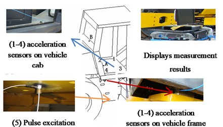
- FE model of a single drum vibratory roller is established based on the modal analysis theory to analyze the natural frequencies of vehicle.
- The design parameters of cab’s isolation system are optimized to reach the maximum value of the first-order natural frequency in order to avoid resonance vibration for cab at low frequency.
1. Introduction
Vibratory roller plays an important role in the field of the construction project on roads, railways, airports, etc. There is a combination of the static force of the vehicle self and the dynamic force of the vibratory drum yielded by an eccentric mass rotating around the drum axis to compact soil, asphalt and other materials in its work process [1-3]. As we know, vibrations in the frequency range of 0.5-10 Hz are considered as the main risk factors to operator’s back problems [1] which seriously affect their mental and physical health. Cab’s isolation system of vibratory roller has an important role to improve vehicle ride comfort. The stiffness and damping coefficients of the cab’s isolation system are analyzed respectively based on a 3D nonlinear dynamic model of a single drum vibratory roller [4]. An experiment was set up to measure ride comfort for vibratory roller when vehicle compacts and moves under four different operating conditions and the numerical simulation results for ride comfort analysis were compared with the experimental results which have verified the validity of models [5]. A nonlinear dynamics model of a single drum vibratory roller was established based on the analysis of the contact physics of the wheel with different soil grounds to evaluate the riding comfort of a vibratory roller [6]. To improve the vehicle riding comfort, the characteristics of the hydraulic mounts are used for vibration isolation of an earth-moving machinery cab [7], the dynamic test and simulations analysis are carried out to find out the main reasons causing cab’s low-frequency sloshing and after an assistant isolator at the back of cab is designed and optimize to alleviate the shaking to acquire the better results [8]. The optimal design parameters of cab’s isolation system are identified based on a combination of the vehicle nonlinear dynamic model of Matlab/Simulink and the NSGA-II genetic algorithm method [9]. A three-dimensional nonlinear dynamic model is established to evaluate the ride comfort of the vibratory roller with the different cab’s isolation mounts [10]. A combined control method of Fuzzy and PID control is proposed to control the cab isolation system of soil compactor based on the non-linear vehicle dynamic model [11].
In this study, a vehicle modal test of a single drum vibratory roller is carried out to find out the natural frequencies of vehicle based on the Belgium LMS dynamic testing and analysis system under single point excitation and multi-point measurement method. A FEM model of a single drum vibratory roller is carried out to find out the natural frequencies of vehicle cab as well as the reasons causing the cab’s low-frequency shaking. The simulation results are compared to the experimental results. Finally, the design parameters of cab’s isolation system are optimized so as to reach the maximum value of the objective function.
2. Vehicle modal test
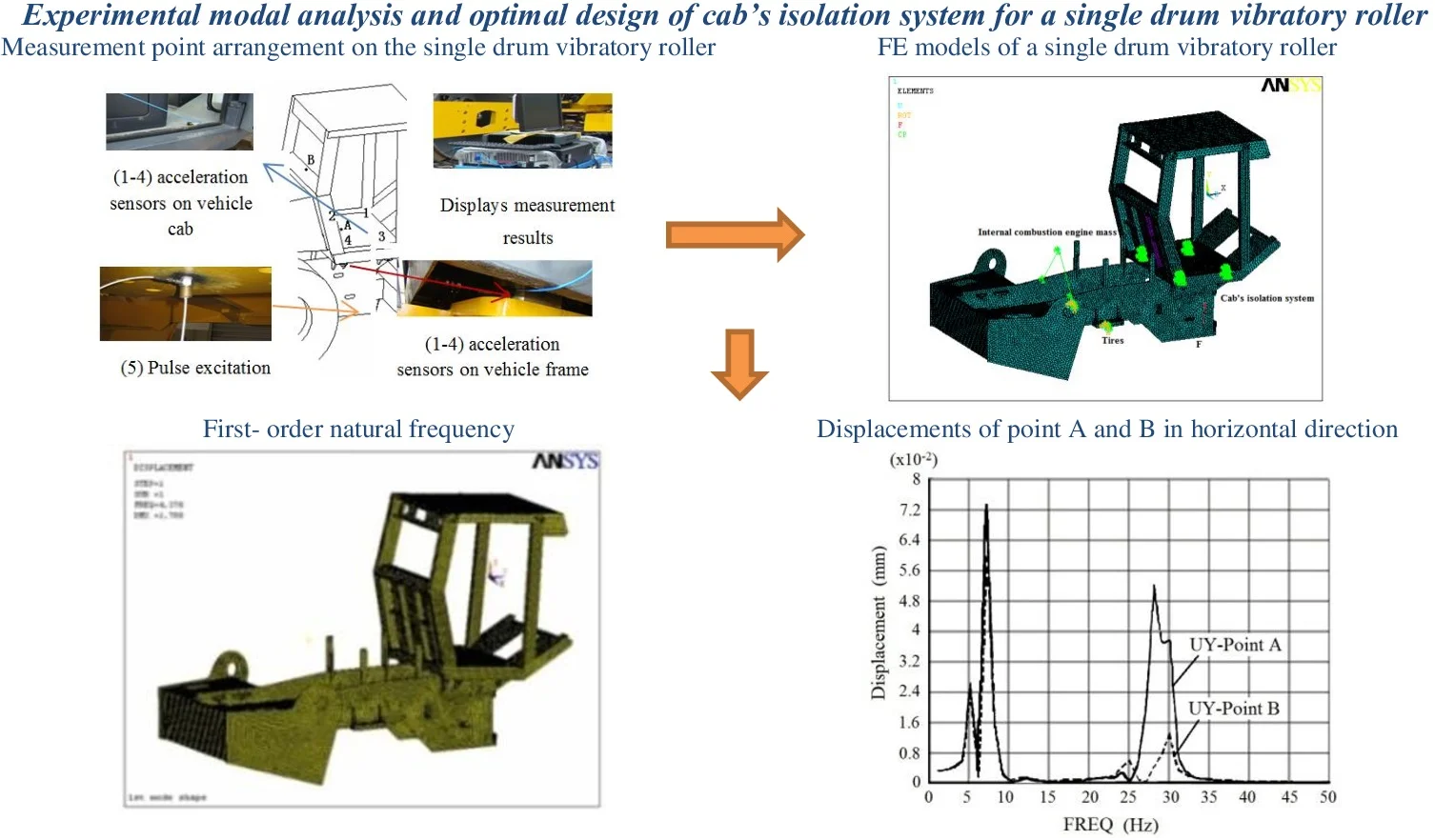
In order to obtain the natural frequency and modal parameters of a single drum vibratory roller, a vehicle model test is carried out to identify the model parameters of vibration roller and find out the natural frequency of the vehicle using the Belgian LMS dynamic test and analysis system. Measure point arrangement on the single drum vibratory roller is shown in Fig. 1.
Fig. 1Measurement point arrangement on the single drum vibratory roller
a) Acceleration sensors
b) Measurement point arrangement
The appearing natural frequencies at measurement points are 0.5 Hz, 4.2 Hz, 14 Hz, 28 Hz, 50 Hz, 272 Hz. The high frequency range affects only a little the cab’s shaking problem, but also the low frequency range such as 0.5 Hz and 4.2 Hz affects greatly on the cab’s shaking problem. Test results obtained through the experimental modal analysis are compared with the simulation results. FEM model and dynamic simulation of vibratory roller will continue to be analyzed below.
3. FEM model and dynamic simulation of vibratory roller
3.1. FEM model of vibratory roller
CAD and FE models of a single drum vibratory roller are built for modal analysis, as shown in Fig. 2. In the FEM model there are 116109 elements including 28941 shell63, 87149 SOLID45, 18 COMBIN14 of spring-damp and one MASS21. Some technical processes are made in the FEM building of vibratory roller: (1) The weight and the center of mass are kept unchanged; (2) Element nodes are connected to equalize weld spots and (3) Isolators are simulated with elements of COMBIN14. The axial stiffness and radial stiffness are 1220 N/mm and 3503 N/mm [1]. The contact stiffness between tire and ground is set as 3480 N/mm [3]; and (4) To obtain the regular elements in size and shape, the small features of model are omitted.
3.2. Modal analysis of vibratory roller
The modal analysis results of the nature frequencies are compared with the obtained experimental results, as shown in Table 1.
Fig. 2CAD and FE models of a single drum vibratory roller
a) CAD Model
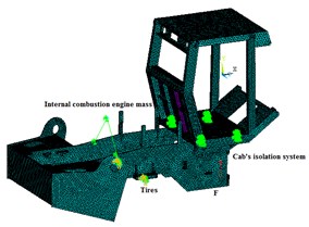
b) FE Model
Table 1Comparison of numerical and experimental results (Unit: Hz)
Model order | Calculation | Test | Error (%) |
1 | 4.38 | 4.2 | 4.3 |
2 | 5.57 | 5.6 | 5.4 |
3 | 6.77 | 6.5 | 4.2 |
5 | 8.11 | 9.5 | 14.6 |
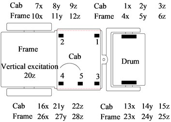
It is indicated from Tab.1 that the modal analysis results of the nature frequencies are in good agreement with the experimental results. The first four modal shapes are shown in Fig. 3. In the first four modes, there isn’t elastic deformation in the cab and frame. It shows the property of rigid movement due to the elastic supporters between cab and frame. The first-order natural frequency 4.38 Hz has much influence on the cab’s shaking in forward direction of vibratory roller. Because the road space frequency 0.013-3.33 m-1 [11], vibratory roller speed 2-5 km/h, the exciting frequency will be 0.07-4.625 Hz. When the modal analysis results are considered again, it is concluded that the reason causing the shock of vibratory roller in forward direction is the first nature frequency of vibratory roller (4.38 Hz) which is just in the frequency range of road excitation. Therefore, in the isolator design, it is necessary to improve the vibratory roller’s first nature frequency higher than road exciting frequency to avoid the resonance in forward direction.
Fig. 3First 4 modes of vibratory roller
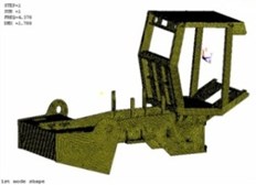
a) First- order natural frequency
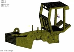
b) Second-order natural frequency
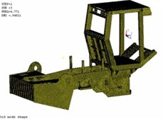
c) Third-order natural frequency
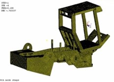
d) Fourth-order natural frequency
4. Optimization design parameters of cab’s isolation system of vibratory roller
According to the modal analysis and the obtained testing results in Section 2 and Section 3, it appears that cab’s rubber isolation system of vibratory roller does not play role an effective in reducing transmission to cab at low frequencies, which will cause resonance vibration as well as reduction in vehicle ride comfort. The first-order natural frequency of the vibratory roller is 4.38 Hz and the road frequency excitation is very close to this frequency. To avoid resonance vibration at this frequency, the design parameters of cab’s isolation system are optimized to the maximum value of the first-order natural frequency by FEA method. The A and B points on Fig. 1(a) are the two points selected to evaluate the cab’s low-frequency shaking in the direction of forward motion.
The objective function with the first-order natural frequency:
where, is cab mass, and are the axial and radial stiffness of a rubber isolator of cab.
Design variable:
State variable:
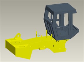
The constraint optimization method is applied to reach the optimal design parameters. The optimal results are 2400 N/mm and 2407 N and the first-order nature frequency is improved from 4.38 Hz to 5.25 Hz. From those optimization results, the optimal parameters of cab’s isolation system are selected for harmonic response analysis under a vertical harmonic excitation with amplify 100 N and frequency range 1 Hz-50 Hz. The frequency response curves at point A and B in horizontal and vertical directions are shown in Fig. 4.
Fig. 4Displacements of point A and B in horizontal and vertical directions
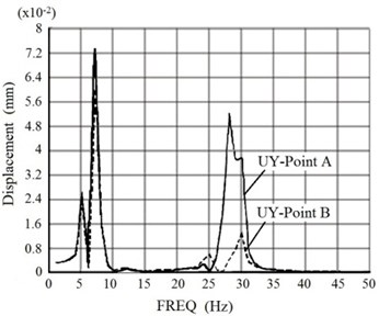
a) Horizontal direction
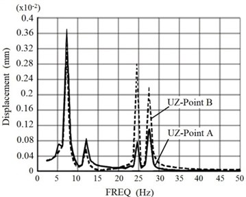
b) Vertical direction
From the results of Fig. 4, it can be seen that the maximum response amplitudes in the forward direction at the A and B points are very close at the first-order nature frequency, thus, cab’s vibrations are effectively controlled at the low frequency and the optimal design parameters of cab’s isolation system can cut off the external excitation frequency above 20 Hz. However, the maximum response amplitudes of the A and B points increase. The optimizing and controlling damper for cab’s isolation system of construction machines have been improved and developed by our research team so as to enhance vehicle ride comfort at low-frequency excitations.
5. Conclusions
This paper focuses on finding solutions to reduce the cab’s low-frequency shaking for a single drum vibratory roller. Firstly, a single-drum vibratory roller modal test is carried out to find out the natural frequency of the vehicle using single point excitation and multi-point measurement method. Secondly, FE models of a single drum vibratory roller is established based on the modal analysis theory to analyze the natural frequencies of vehicle. The modal analysis results of the nature frequencies are in good agreement with the experimental results. Finally, the optimal design parameters of cab’s isolation system of vibratory roller is found out so that resonance vibration for cab is avoided and the cab’s low-frequency shaking in the direction of forward motion is reduced.
References
-
Quynh Le Van Vibration Study and Control Cab of Vibratory Roller. Southeast University, Nanjing, China, 2013.
-
Pietzsch D., Poppy W. Simulation of soil compaction with vibratory rollers. Journal of Terramechanics, Vol. 29, Issue 6, 1992, p. 585-597.
-
Adam D., Kopf F. Theoretical analysis of dynamically loaded soils. European Workshop Compaction of Soils and Granular Materials, 2000, p. 207-220.
-
Le Van Quynh, Vi Thi Phuong Thao, Nguyen Thanh Cong Influence of design parameters of cab’s isolation system on vibratory roller ride comfort under the deformed ground surfaces. International Research Journal of Engineering and Technology (IRJET), Vol. 6, Issue 6, 2019, p. 1974-1978.
-
Le V. Ride Comfort Analysis of Vibratory Roller via Numerical Simulation and Experiment. DEStech Transactions on Engineering and Technology Research, 2017.
-
Le V. Q., Zhang J. R., Liu X. B., et al. Ride comfort evaluation of vibratory roller under different soil ground. Transactions of the Chinese Society of Agricultural Engineering, Vol. 29, 2013, p. 39-47.
-
Sun Xiaojuan, Zhang Jianrun Performance of earth-moving machinery cab with hydraulic mounts in low frequency. Journal of Vibration and Control, Vol. 20, Issue 5, 2014, p. 724-735.
-
Quynh L. V., Zhang J. R., Jiao G. W., Liu X. B., Wang Y. Vibration analysis and optimal design for cab’s isolation system of vibratory roller. Advanced Materials Research, Vol. 199, 200, p. 936-940.
-
Le V. Q., Nguyen K. T. Optimal design parameters of cab’s isolation system for vibratory roller using a multi-objective genetic algorithm. Applied Mechanics and Materials, Vol. 875, 2018, p. 105-112.
-
Liem N. V., Run Z. J., et al. Vibration analysis and modeling of an off-road vibratory roller equipped with three different cab’s isolation mounts. Shock and Vibration, Vol. 2018, 2018, p. 8527574.
-
Vanliem Nguyen, Renqiang Jiao, Vanquynh Le, Anhtan Hoang Performance of PID-Fuzzy control for cab isolation mounts of soil compactors. Mathematical Models in Engineering, Vol. 5, Issue 4, 2019, p. 137-145.
-
Anderegg R., Kaufmann K. Intelligent compaction with vibratory rollers: Feedback control systems in automatic compaction and compaction control. Journal of the Transportation Research Board, Vol. 1868, Issue 1, 2004, p. 124-134.
-
GB/T7301-1986. The Standard of the Vibration Input of Vehicle and the Road Spectrum, 1986.
Cited by
About this article

The work described in this paper was supported by Thai Nguyen University of Technology for a scientific project (Code: T2018-B25).
