Abstract
The passengers of electric vehicles are exposed to strong magnetic fields associating to the vehicle equipment, devices and electric motors. The aim of study is to demonstrate the necessity of an implementation of the authors US Patent which has 4 combined functions in electric vehicle application: mitigate the torsional vibrations of rotating part, serve as a flywheel improving the quality of rotation, generate additional electricity and shielding the magnetic fields. The mathematical modeling, simulation analysis and experimental study were done for electric vehicle. It is shown that the usage of proposed energy harvesting damper could generate up to 11 kW of additional electricity, while reducing the levels of torsional vibrations in driveline, improving the quality of rotation and eliminate the impact of magnetic fields.
1. Introduction
The seats of electric vehicles (like in all types of automotives) are very close to an electric system of significant power, for instance, electric motors and batteries. The short distance between the power units and the seats means that the passengers could be exposed to high level magnetic fields in electric vehicles for a considerable amount of time. The scientific evidences of negative health effects are widely described in literature (see for example [1]). The scientists and engineers are trying to make electric vehicles safe and protected from the magnetic radiation (see for instance [2, 3]) and to meet health regulations like [4, 5] and others related documents. It is demonstrated such attempt in current study using patented solution. The invented [6] vibration energy harvesting damper (VEHD) is designed to fulfill 4 combined functions in electric vehicles: mitigate the torsional vibrations of rotating part, serve as a flywheel improving the quality of rotation, generate additional electricity and shielding the magnetic fields.
The presented study is conducted to demonstrate the extraordinary advantages of installation of that VEHD consisting of two main components: tuned mass damper (TMD) and electricity generator. TMD is represented by torsional vibration damper (TVD) in current research [7]. The feature of proposed VEHD is in self-tuning to dampen harmonics over a wide frequency range. The application of developed VEHD in electric vehicles (EV) system “electric motor-transmission-wheels” is demonstrated in the present study using the Tesla 3 parameters numerical modeling and experimental tests. The results were compared to models “original EV – no VEHD installed” and “EV with VEHD installed”.
2. Metered parameters in original EV
The electric motor used in EV has tremendous advantages; one of these advantages is that it creates high torque at low speeds, leading to a high rate of acceleration. The paper study is based on a certain EV. EV equipped electric motor by 202 kW with transmission. First of all, this car was tested during city traffic mode drive; there were no alterations and changes of car scheme.
The electric car driving propulsion subsystem consisting of electric motor, transmission and wheels was the object of study. That subsystem contains the chain of coupled shafts. Each shaft is rotating with a certain angular speed .
The electric motor used in EV has tremendous advantages; one of these advantages is that it creates high torque at low speeds, leading to a high rate of acceleration.
However, the rapid rise in torque of an electric motor develops intensive shaft vibrations accompanying by a jerk [8].
There are several negative outcomes of the jerk existence, and the initial outcomes are the irregularity of rotational speed and torsional vibrations.
The rotational speed of motor shaft is not constant during one revolution even for stationary regime of operation, and varies from its minimal value to its maximal value . Let denote a mean value of the shaft rotational speed , determined as . Then the quality of a flywheel can be characterized by coefficient of rotation speed fluctuation . That parameter reflects the quality of a rotation: the more the the greater rotational speed changes during a revolution, 0 means uniform rotation which in a real practice cannot be achieved. From Industry Requirements the guiding values for for DC electric motors are in range of 0.005-0.01, and for AC motors – 0.003-0.005. The different types of flywheels are used for keeping within these values. The recorded number was 0.015 during current preliminary tests, and it means that special flywheel needed for solving that problem.
Torsional vibrations of motor shaft are characterized by vibrations frequency and amplitude of twist angle 2. It is desired to minimize the twist angle amplitude, ideally to reduce it down to zero, in steady-speed motors operation. The measured values of a peak-to-peak twist angle are in range 0.36-2.30 degrees for different regimes of electric motor’s operation while it must be less than 0.4 degrees according to accepted industry regulation [7]. The torsional vibration damper is servicing for minimization of an intensity of the torsional vibrations. The twist angle of 0.52 degrees was registered during discussed preliminary tests, and that is why that special TVD needed to fix this problem.
Specific scrutiny was paid to the measurements of electric field radiation and magnetic field emission at front right passenger seat. The measurements were done using BENETECH Electromagnetic Radiation Tester GM3120.
The typical peak readings registered for front right passenger seat during city regular driving mode are: 23 V/m for electric field and the tester indicates it as SAFE; and 5.34 T for magnetic field, and the tester indicates it as HARMFUL. This fact pinpoints that something must be done for avoiding such situation. The authors proposed to check the availability of VEHD usage for fixing the examined negative situation [6, 7].
3. The specificity of VEHD usage for EV
The proposed device based on US Patents [6] combines several properties: the torsional vibration damper; a flywheel; electricity generator; magnetic field shield. The core simplified model of proposed device is shown in Fig. 1. It was designed and fabricated VEHD based, and installed in a system “electric motor-transmission-wheels” of the tested car (Fig. 1).
The shaft 1 is rotating with angular speed around center point O (see Fig. 1). The solid base body of device is composed by hub 2, which is strictly connected to circled plate 3 carring the outer rim 4. Hub 2 is firmly mounted on the shaft. A cantilever spring (beam) 7 is connected to rim 4 and installed with the gab relative to hub 2. Masses or selectors 6A are mounted on springs 7, so that they can slide along them. The selectors 6A are also connected to the hub 2 by springs 5. Hence, selector 6A could oscillate in radial direction. The radial movements of selectors 6A is also constrained by the counter-forces due to the compression or extension of helical springs 5. Further, the selectors’ 6A movements perpendicular to the radius are limited by the counter-forces due to deflections of springs 7. The design of the device is symmetrical in order to ensure the inertia moment is centered about point O, so it could include 2, 3, 4 and so on selectors 6A (example of a device with 2 selectors is in Fig. 2). An increase in angular velocity leads to an increase in the outward radial displacement of the selector 6A, which, in turn, leads to a change in the point of application of the bending force acting on cantilever spring 7. This also leads to a decrease in the length of the spring 7 and, accordingly, an increase in its stiffness. These effects combined with the appropriate choice of the cantilever spring dimensions lead to a decrease in oscillations in the range of operating frequencies . Hence it is a possibility to be tuned on current speed of rotation, and automatically to be re-adjust to changing . Furthermore, it is shown that selectors are rigidly connected to permanent magnets 6B. It could be one structure (permanent magnet) in some applications instead of couple 6A-6B. The magnets 6B are surrounded by sheaths structures 9 with pick-up coils 8 mounted in it. Displacements of magnet 6B inside of coil 8 initiate a current, and an electromagnetic bond between them occur. This result to elimination of torsional vibrations and irregularity in the shaft’s rotational speed, as well as to power generation by the subsystem “coil 8 – magnet 6B”.
Fig. 1A schematic view of VEHD
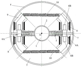
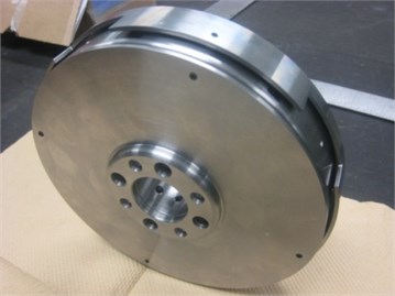
Fig. 2A fabricated VEHD
Let’s build the differential equations for EV study like presented in [7]. The total examined system is rotating with angular speed . The angle is the angle of a deflection (angular movement) of the shafting system. Further, is inertia moment of the shafting system including the motor shaft, transmission, and wheel. The shafting system is connected to VEHD solid part by flexible element imitating stiffness properties of the shafting system, and numerically modeled by coefficient and viscous friction coefficient of loss . VEHD solid part has a moment of inertia . Tuned mass damper is represented in considered case by torsional vibration damper with magnets having a inertia moment of all movable parts (see Fig. 1) of VEHD, or ( is the sum of selectors 6A and magnets 6B masses, is a displacement of masses 6A-6B in radial direction using beam 7). The VEHD’s movable parts are connected to its solid parts by means of springs with stiffness and viscosity . The solid part of VEHD is vibrating in the same direction as the shafting system, so its displacement is described by coordinate like for the shafting system. The angular vibrations of movable torsional vibration damper with magnets relative to the solid parts of VEHD are described by the angle . The torque would be presented by . Electromagnetic subsystem of VEHD is inducing current , and have inductance and electrical resistance , where is coil resistance and is load resistance. The VEHD dynamics is described by the following system of differential equations:
where “·”, is the linkage factor, which in most of cases could be determined as , where is field flux and is characteristic size. It was mentioned during discussion of the properties of a device shown in Fig. 1, that mechanically it is possible to keep natural frequency equals to , where is the current stiffness value of cantilever spring 7 (see Fig. 1).
It is well known that the rapid rise in torque of an electric motor develops intensive shaft vibrations accompanying by a jerk [8]. There are several negative outcomes of the jerk existence, and the initial outcomes are torsional vibrations and the irregularity of rotational speed.
For further research of jerk’s problem it was recorded the applied torque during start driving process (see brown curve in Fig. 3). The brown curve is plotted in a following coordinates in Fig. 3: abscissa is a time (in seconds) and ordinate is a torque (in Nm). The blue curve represents its theoretical approximation.
Fig. 3The torque behavior in first five seconds
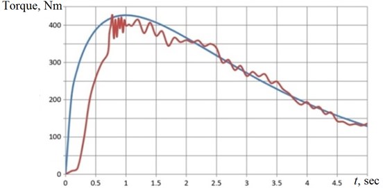
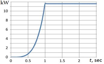
The torque rises to maximum less than in one second and after that declines with some ripples. It is very difficult to use such curve for numerical analysis of dynamics in a system of Eq. (1). Hence, it was found the approximation formula for torque: . Solving the Eq. (1), it is possible to build the theoretical torque curve like shown in Fig. 3 by blue line. One can see that suggested approximation is sufficient enough. Also, it is possible now to plot the relationship like presented in Fig. 4(a). Naturally that the variations of impacted the Generator portion of VEHD and the electrical power generated as a result (see Fig. 4(b)). The observer can see that the generated power is growing up exponentially in one second and is keeping (by restrictors [6]) at the constant level of 11.55 kW.
Fig. 4A conversion in VEHD in first five seconds: a) φt; b) produced power
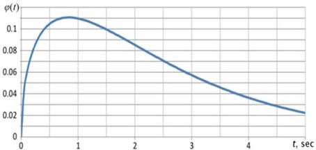
a)
b)
4. The final experimental results
The real drive (specifically in city driving) makes the configuration of a picture in Fig. 4(b) quite different, the sequence of zeros and extremes are random (depending on driving circumstances) and values of flat top parts are random and different. The observing result of a discussed VEHD implementation tells that one can state that the average produced VEHD power is about 8 kW, while mitigating the system’s torsional vibrations (recorded twist angle is 0.27 degrees after VEHD installation) and servicing as a flywheel (now recorded irregularity of rotational speed is 0.004).
The VEHD (using the properties of synchronized close loop control subsystem [6], and being implemented into car drive system) annihilates the electric field and reduces the registered peak value of magnetic field to SAFE region with numbers of 0.17 T. The authors understand that these experiments are first stage of the long distance which must be covered for an implementation in the real industrial practice of presented studies. Moreover, it is necessary to appeal to public, science and engineering societies, governments and international bodies for developing and introducing the regulatory standards (for example like SAE International and others) for establishing the safe parameters of electromagnetic fields inside of electric vehicles.
5. Conclusions
The various dynamical problems of EV operation (such as raised magnetic fields, rotational speed irregularities and torsional vibrations in drive system) can be successfully solved using invented schemes of energy harvesting emissions free devices – Vibration Energy Harvesting Dampers. That device combines four functions: shielding the magnetic fields while mitigating the torsional vibrations of rotating parts, improving the quality of rotation, and generating additional electricity.
The conducted study demonstrates that proposed VEHD reduces the magnetic field inside electric vehicle, mitigates the torsional vibrations of rotating parts, serves as a flywheel improving the quality of rotation (while protecting the electric motor) and generates the additional electricity; that electricity is feeding batteries, wireless autonomous electronic units and so on.
Also, it is important to underline that electric vehicles need the regulatory standards to pronounce the safe parameters of electromagnetic fields inside of electric vehicles.
References
-
Tiikkaja M.,et al. Electromagnetic interference with cardiac pacemakers and implantable cardioverter - defibrillators from low-frequency electromagnetic fields in vivo. Europace, Vol. 15, 2013, p. 388-394.
-
Kurt E., Uzun Y. Nonlinear Problems in Piezoelectric Harvesters under Magnetic Field. Energy Harvesting and Energy Efficiency Technology, Methods, and Applications, Cham, Springer International Publishing, Switzerland, 2017, p. 107-142.
-
Hamza D.,et al. Implementation of a novel digital active EMI technique in a DSP‐based DC/DC digital controller used in electric vehicle (EV). IEEE Transactions on Power Electronics, Vol. 28, Issue 7, 2013, p. 3126-3137.
-
Vecchia P., et al. Guidelines on limits of exposure to static magnetic fields. Health Physics, Vol. 96, Issue 4, 2009, p. 504-514.
-
Vecchia P., et al. Guidelines for limiting exposure to time varying electric and magnetic fields (1 Hz-100 kHz). Health Physics, Vol. 96, Issue 6, 2010, p. 818-836.
-
Nerubenko G., et al. Vibration Energy Harvesting Damper. U.S. Patent Application No. 16/119,346, 2018.
-
Nerubenko G., et al. Vibration energy harvesting dampers in all terrain amphibian vehicle. Proceedings of ICSV26, Montreal, 2019.
-
Mohit Batra Dynamics and Model-Predictive Anti-Jerk Control of Connected Electric Vehicles. Ph.D. Thesis, University of Waterloo. Waterloo, Ontario, Canada, 2018.
About this article

Special thanks to Jerzy Abramovski for tremendous help, especially during experimental session.
