Abstract
The aim of this paper is to design a combination of a magnetoelectric-electromagnetic (ME-EM) vibration converter in order to reach an improved energy outcome. In this paper, the influence of magnets polarization and magnetoelectric transducer and coil direction are investigated. For this purpose, a finite element model is developed using one coil, one ME transducer in a magnetic circuit. Simulation results show that a better magnetic field distribution and variation is reached, if the magnetic circuit magnets are placed in attraction. Radial polarization shows decisive advantages in comparison with axial polarization. The placement of coil parallel to the magnetic circuit direction and the magnetization of the ME transducer along its width is the optimal direction relative to the magnetic circuit.
1. Introduction
Different techniques are used to harvest energy from vibration sources, such as electrostatic, electromagnetic [1-3], piezoelectric [4-6], and magnetoelectric [7-10]. Improving the power density of such device is one of the biggest challenges for research in this field. A high energy output can be only reached by an optimized harvester design taking the parameters of the available vibration into account. Such devices require high reliability for long life time to be implemented in real applications. The main methods to improve the outcome of vibration converters are the use of combined converters based on the same principle [11], or different principles [12] and also by the improvement of energy management design [13].
In 2006, Shahruz developed multi piezoelectric converter using cantilevers with different size to reach bandwidth converters with high energy outcome [14]. The realization of this system is complex and is not enough reliable to ensure long life time for the converter.
In 2009, Tadesse et al. developed combined converter solution based on EM and piezoelectric principles. It can deliver 0.25 W for 20 Hz frequency excitation and 35 g of acceleration [12]. In this case, the life time of such solution. Recently, Qiu et al. developed a combined converter using EM and ME principle [15]. The developed system is just a laboratory concept using a cantilever beam in which one transducer is attached surrounded with coil and magnetic circuit.
In this context, the aim of this research is to realize a new concept of vibration energy converter ensuring high reliability and high energy outcome within a challenging size. The converter consists on the combination of two principles which are the EM principle and ME principle. The novelty within this work is to include within the EM converter, the ME converter through the magnets air gap. This enables to improve the reliability of the converter and increase its energy outcome compared to a single electromagnetic converter within the same volume. The challenge is to define the suitable design to get as much energy within a limited size.
This paper is consists of three sections. In Section 1, description of the used energy principles for the combined converter is presented. Section 2 is devoted to investigate the finite element analysis model for the converter to study the magnetic circuit and the magnetoelectric transducer.
2. Combined vibration converter principle
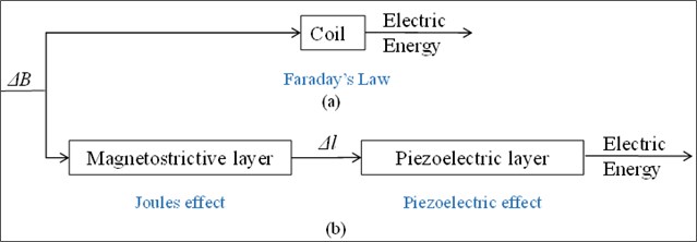
The proposed converter is based on EM and ME principle. For the EM, it consists principally on the use of moving magnets surrounded with a fixed coil. The vibration is transmitted to the converter using magnetic spring by placing two magnets in repulsive direction.
In this case, electrical energy is generated through the coil due to the presence of variation of the magnetic field (Fig. 1(a)). For the ME, it is based on the placement of magnetostrictive-piezoelectric transducer between the magnets. As first, a deformation will occur on the magnetostrictive layers due to the magnetic field change. This will be transmitted and applied to the piezoelectric layer placed between two MS layers as a stress, which will lead to generate an induced voltage through it (Fig. 1(b)).
Fig. 1a) Electromagnetic principle, b) magnetoelectric principle
3. Magnetoelectric transducer optimization
This section is devoted to model the combined electromagnetic magnetoelectric converter based on finite element model. Mainly, the magnetic field level and its variation are evaluated since they present the main parameter affecting the converter performance.
3.1. Finite element model
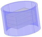
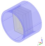
3D finite element model is developed to evaluate the converter (Fig. 2). NdFeB material is used for the magnets due to its strong energy density. For the coil, copper material, due to its higher conductivity, is selected. Terfenol-D and PZT-5H are chosen for the magnetostrictive and piezoelectric layers due to the high reached magnetoelectric coupling coefficient in this case [16].
Fig. 2Developed model for the combined electromagnetic magnetoelectric converter
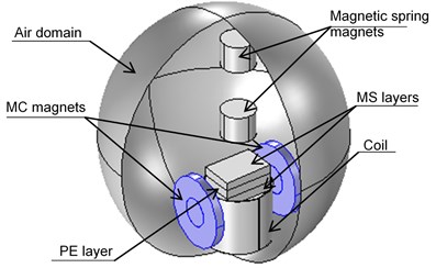
The magnetoelectric principle is defined for the converter with the magnetic circuit, where the magnetization is studied in the following. Through the air gap, we define the magnetoelectric transducer by one piezoelectric layer (PZT-5H) bonded between two MS layers (Terfenol-D). The used mechanical properties for the Terfenol-D are defined in Table 1.
To study this model, AC/DC module including two physics is used. The first one is the magnetic field physic in which boundary conditions, loads and properties of coil and magnets are defined. Then, the solid mechanics physics is used to define the boundary conditions for the MS layers.
Table 1Properties of Terfonol-D material
Material properties | Value |
Young’s modulus | 25-35 GPa |
Poisson’s ratio | 0.45 |
Density | 7870 kg/m3 |
Electric conductivity | 0 |
Relative permittivity | 1 |
Saturation magnetostriction | 2000 ppm |
Saturation magnetization | 15×105 A/m |
3.2. Magnetic circuit magnets effect
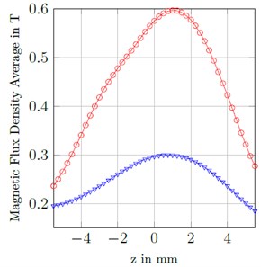
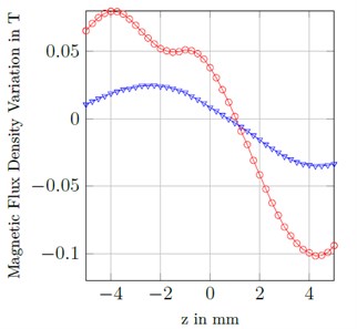
This section is dedicated to investigate the effect of the magnetic circuit magnets magnetization. For this purpose, finite element model is developed, where the magnetic field level and its variation are evaluated relative to the magnets magnetization; repulsion or attraction. Fig. 3(a) presents the magnetic field evaluation for both cases. A maximum average of magnetic field level passing along both magnetostrictive layers of 0.3 T and 0.6 T is achieved for repulsive and attractive magnets respectively. More interesting is the study of the variation of the magnetic field, due to its effect on the output performance of the converter. For a 1mm of displacement, results have proven that it is ∼30 % higher in the case of attractive magnets as shown in Fig. 3(b).
Fig. 3a) Average, b) variation of magnetic flux density through the MS layers for attractive and repulsive magnetization for the MC magnets

a)
b)
Fig. 4Magnetic flux density lines in the case of magnets placed in a) repulsion, b) attraction
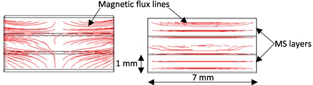
This is due to the fact that in the case of the repulsive magnets, the distribution of magnetic flux lines is not homogenous through the MS layers as shown in Fig. 4(a). In case of attraction, an homogenous distribution and a continuous magnetic flux lines passing through the MS layers is ensured, which leads to a better magnetoelectric transducer performance (Fig. 4(b)).
3.3. Study of the combination effect on the converter performance
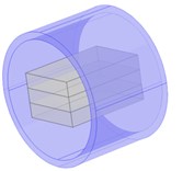
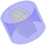
In this section, the effect on the combination of both magnetoelectric and electromagnetic principles is investigated. For this purpose, a finite element model is defined, where the coil position and direction relative to the magnetoelectric transducer is studied. Fig. 5 presents the four studied cases for the two principles combination.
Fig. 5Different evaluated directions for the coil and the ME transducer: a) D1D1, b) D1D2, c) D2D1, d) D2D2
a)
b)
c)
d)
Results show that a difference of magnetic field level is reached through the coil for the different directions. Better compromise of higher magnetic field level is reached in the case of D1D1 directions for the coil and ME transducer which is presented by Fig. 5(a). This presents the case, where the magnetic circuit is placed in a way that the magnetoelectric transducer
In this case the coil is placed perpendicular to the magnetic circuit and in a way that the ME transducer is magnetized along its width.
Table 2Magnetic field variation relative the coil and ME transducer directions
Coil direction | ME transducer direction | |||
D1 | D2 | |||
MF through the coil (Oe) | MF through the MS layer (A/m) | MF through the coil (Oe) | MF through the MS layer (A/m) | |
D1 | 531 | 263.70 | 444 | 66.30 |
D2 | 505 | 263.30 | 564 | 66.97 |
4. Conclusions
In this paper, a finite element analysis for an electromagnetic-magnetoelectric vibration converter is studied. Results illustrate that the use of magnetic circuit magnets placed in attraction enables to ensure a higher distribution of the magnetic field lines through the magnetostrictive layers which leads to a higher stress affecting the piezoelectric layer. The placement of the coil and the ME transducer in the direction D1D1 presents the optimal direction for a higher and homogenous magnetic field distribution. The main advantage of the proposed solution that it allows a better reliability and life time for the converter to be implemented in real applications due to the ability to generate energy through two principles that can work independently. The converter has the advantage to be designed to work under real vibration profiles, where an amplitude of displacement limited to 1 mm is applied and a low frequency in the range of 20 Hz to 30 Hz.
References
-
Bradai S., Naifar S., Viehweger C., Kanoun O., Litak G. Nonlinear analysis of an electrodynamic broadband energy harvester. European Physical Journal: Special Topics, Vol. 224, Issue 14, 2015, p. 2919-2927.
-
Cepnik C., Lausecker R., Wallrabe U. Review on electrodynamic energy harvesters; A classification approach laboratory of micro actuators. Micromachines, Vol. 4, 2013, p. 168-196.
-
Bradai S., Naifar S., Keutel T., Kanoun O. Electrodynamic resonant energy harvester for low frequencies and amplitudes. IEEE International Instrumentation and Measurement Technology Conference, 2014.
-
Steven R., Henry A. A review of power harvesting using piezoelectric materials (2003-2006). Smart Materials and Structures, Vol. 16, Issue 3, 2007, https://doi.org/10.1088/0964-1726/16/3/R01.
-
Zhua D., Beeby S., Tudor J., White N., Harri N. Improving output power of piezoelectric energy harvesters using multilayer structures. Procedia Engineering, Vol. 25, 2011, p. 199-202.
-
Roundy S., Wright P. K. A piezoelectric vibration based generator for wireless electronics. Smart Materials and Structures, Vol. 13, Issue 5, 2004, p. 1131-1142.
-
Naifar S., Bradai S., Viehweger C., Kanoun O. Response analysis of a nonlinear magnetoelectric energy harvester under harmonic excitation. European Physical Journal: Special Topics, Vol. 224, Issue 14, 2015, p. 2897-2907.
-
Suna J., Song C., Yunhee C., Seungjun L., Hyang L., Chang Hyeon J. A low frequency vibration energy harvester using magnetoelectric laminate composite. Journal Smart Materials and Structures, Vol. 22, Issue 11, 2013, p. 115037.
-
Hakeim T., Zhuoxiang R. Finite element modeling of magnetoelectric laminate composites in considering nonlinear and load effects for energy harvesting. Journal of Alloys and Compounds, Vol. 615, 2014, p. 65-74.
-
Bradai S., Naifar S., Kanoun O. Finite element analysis of combined magnetoelectric-electrodynamic vibration energy converter. Journal of Physics Conference Series, Vol. 660, Issue 1, 2015, p. 12111-12115.
-
Dibin Z., Michael J., Stephen P. Strategies for increasing the operating frequency range of vibration energy harvesters: a review. Measurement Science and Technology, Vol. 21, Issue 2, 2010, p. 022001.
-
Tadesse Y., Zhang S., Priya S. Multimodal energy harvesting system: piezoelectric and electromagnetic. Journal of Intelligent Material Systems and Structures, Vol. 20, Issue 5, 2009, p. 625-632.
-
Zhu D., Roberts S., Mouille T., Tudor M. J., Beeby S. P. General model with experimental validation of electrical resonant frequency tuning of electromagnetic vibration energy harvesters. Journal Smart Materials and Structures, Vol. 21, Issue 10, 2012, p. 105039.
-
Shahruz S. M. Design of mechanical band-pass filters for energy scavenging. Journal of Sounds and Vibration, Vol. 292, Issues 3-5, 2006, p. 987-998.
-
Qiu J., Chen H., Wen Y., Li P. Magnetoelectric and electromagnetic composite vibration energy harvester for wireless sensor networks. Journal of Applied Physics, Vol. 117, Issue 17, 2015, p. A331.
About this article

