Abstract
In order to increase the stability and movement safety of electric vehicles (EV) under various operation conditions, the battery mass distribution on the EV floor and its load dynamics are concerned in this study. An EV dynamic model with the different battery mass distributions on the EV floor is established and investigated. The EV dynamic equations are then solved via the Simulink model built on Matlab software. The acceleration responses at centre of gravity of the EV and wheel dynamics are two objective functions for evaluating the EV movement safety. The research results show that the optimal position of the battery mass distribution on the EV floor and the ratio between the battery mass and the EV body mass should be reached with from 1.2 to 1.4 m and 0.6, and the EV’s velocity should be from 20 to 35 m/s, therefore, the EV movement safety is remarkably improved.
Highlights
- The battery mass distribution not affects on the vertical acceleration of the EV floor, but it strongly influences the pitch acceleration of the EV floor.
- The optimal position of the battery mass distribution is reached with x from 1.2 to 1.4 m on the EV floor and lambda ≤ 0.6. It means that the EV movement safety is obviously improved at a range of x.
- The research results can be applied to optimize the battery mass and its mass distribution on the EV floor to enhance the vehicle ride comfort apart from improving the EV movement safety.
- the optimal position of the batty mass set-up with its minimum vibration can reduce the vibration and impact between the batteries, therefore, the batteries' durability can be significantly improved.
1. Introduction
In order to save energy and reduce environmental pollution, clean energies such as bio-fuels, electric batteries, etc. were researched and applied on the engine of vehicles to replace the increasingly exhausting fossil energy sources and environmental pollution [1, 2]. Particularly, the fuel cells or electric batteries were gradually studied and used on electric vehicles (EV) [3, 4]. The design and optimization of the power battery and torque converter of electric motors to increase the dynamic stability of the EV were also considered [5, 6]. The influence of the vibration of in-wheel motors on the wheel dynamic forces had been analyzed [4]. The results showed that the impact of the vertical force of in-wheel motors greatly affected the vibration stability of the EV. Therefore, the isolation between the axle of the wheel and the bearing of the rotor had been added to reduce the EV’s vibration and increase the EV’s stability [3, 7, 8]. To further improve the ride comfort and stability of the EV, the vibration isolation of the in-wheel motor and EV’s suspension system were then controlled [7, 9]. The results indicated that the ride comfort and movement safety of the EV were significantly improved. However, the EV mass with the battery mass distribution on the EV floor could also affect the EV vibration and movement safety when the EV travels with its high velocity. This issue has not yet been concerned in the existing studies.
With traditional vehicles, especially cars, the internal combustion engines (ICE) were mostly located in the front of vehicles, thus, the center of gravity of vehicles was also biased forward, so it affected significantly stability of vehicles when moving at high speed and the operation of the brake system [10-12]. The ICE is difficult to place in the middle or in the back of cars, due to the specific structure of cars. Therefore, the anti-lock brake system (ABS) had been used to increase the stability and movement safety of vehicles when traveling with the high velocity [13]. With the EV using electric batteries, the advantage of electric batteries compared to the ICE is the small weight and size, thus, the electric battery can be installed in the front, middle, or rear locations of the EV to improve the car’s space. However, the installation location of the electric battery can affect the dynamic load distribution of the wheels and vibration of the EV body which directly affects the EV’s stability and movement safety. Therefore, it should be studied.
This paper, the effect of the mass distribution of electric battery on the EV movement safety is researched. A dynamic model of the EV with the various battery mass distributions on the EV floor is established to simulate the results. The root-mean-square (RMS) of the acceleration responses in the vertical and pitching motions of the EV and of the wheel dynamics are chosen as the objective functions. The excitations of the in-wheel motors and road surface roughness are used to simulate the results based on the numerical method and Matlab/ Simulink software.
2. Materials and methods
2.1. Models of battery mass distribution and EV dynamics
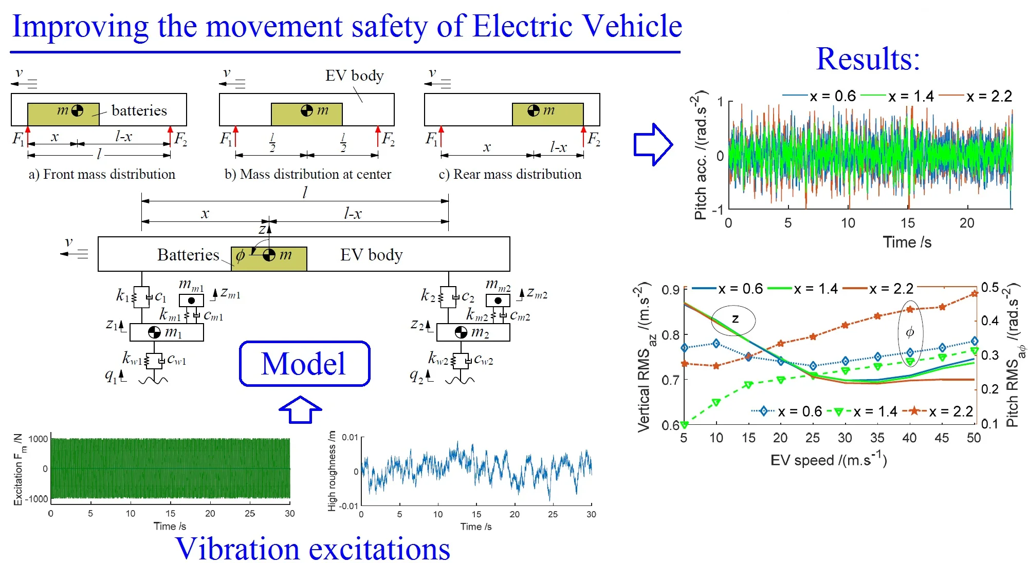
Three types of battery mass distributions on the EV floor including the front mass distribution, mass distribution at the center, and rear mass distribution are modeled in Figs. 1(a-c), respectively. A nonlinear dynamic model of the EV with the in-wheel motors and random distribution of the battery mass is also assumed and established in Fig. 1(d) to analyze the effect of electric battery mass distribution on EV's movement safety.
Fig. 1Three cases of the battery mass distributions on the EV floor and its dynamic model
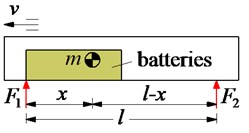
a) Front mass distribution

b) Mass distribution at center
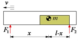
c) Rear mass distribution
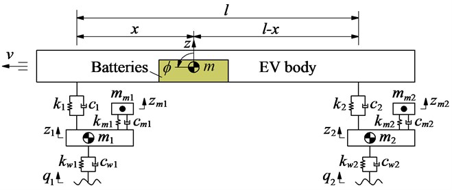
d) EV dynamic model with random battery mass distribution on the EV floor
In Fig. 1 , , and are the vertical displacements of the EV body, front axle, and rear axle, respectively; is the angular displacement of the EV body; , , and are the masses of the batteries and EV body, front and rear axles; and the in-wheel motors, respectively; {, , and } and {, , and } are stiffness and damping coefficients of the EV suspension systems; isolation of in-wheel motors, and wheels, respectively; is excitations of the road surface; is the VE length, is the distance from the centre of gravity of the battery mass distribution and the EV body to the front axle which should be explored in this study.
Based on the EV dynamic model in Fig. 1, and by applying Newton’s second law of motion, the motion equations of the EV can be represented in the matrix form as follows:
where , , and are respectively the mass, damping, and stiffness matrices of the EV; , and are the vectors of the acceleration, velocity, and displacement; and and are the force vectors of the vibration excitations of the in-wheel motors and road surfaces.
Both the excitation forces of and of the in-wheel motor and road surface roughness are in calculated in Section 2.2.
2.2. Excitation vibrations
In the traveling condition of the EV, there are two main vibration excitations including the in-wheel motors and road surface roughness at the wheel contacts. To analyze the influence of the battery mass distributions on the EV movement safety, two types of excitation road are applied and described as follows:
The excitation of the in-wheel motor: The nonlinear dynamic model of the in-wheel motor driving of the EV was researched and applied [3, 4]. Based on the model, the excitation forces of bearing moved in the journal of the in-wheel motor were determined by two main excitations in the - and -directions and defined as follows:
However, this research mainly analyzes the vertical vibration of the EV model, therefore, the excitation forces in the in-wheel motors are only considered by the vertical excitation forces of in-wheel motors, and they are rewritten by:
where is the total mass of the motor rotor, rim, and wheel (kg); is the eccentricity of the wheel or rotor (m); 𝜔 is the angular velocity of the wheel or rotor (rad/s); is the wheel radius (m); and is the EV moving velocity (m/s). The excitation force of the in-wheel motor at the EV speed at 20 m/s is then simulated and plotted in Fig. 2(a).
The excitation of the road surface roughness: To establish the random road surface, the white noise speed spectrum represented with a realization of a random process via its frequency spectrum density (FSD) is applied to describe the random road in the time domain. Its equation can be expressed as follows [14]:
where is the spatial frequency of the road surface; is the random signal of the white noise; is the road roughness power spectrum density (PSD) chosen in Ref. [14].
Based on Ref. [14], the PSD of road surface roughness of levels B at 20 m/s of the EV is also chosen to simulate the excitation of the road surface roughness. The high roughness of the road with the simulation time of 30 s is shown in Fig. 2(b).
Fig. 2Two types of EV vibration excitations
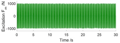
a) Excitation force of in-wheel motor
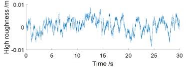
b) Excitation of road surface roughness
3. Simulations and discussions
When the EV traveling with the high velocities, both the body vibrations and wheel’s impact forces on the road surface can be increased following the EV velocity. Thus, to improve the EV movement safety, the influence of electric battery mass distribution on EV’s movement safety is researched. To simulate and evaluate the results, the RMS acceleration responses of the EV floor and wheels are chosen as objective functions [14, 15]. Their equation is described by:
where is defined as the motion of the vertical EV, pitch EV, vertical front axle, and vertical rear axle, respectively; is defined as the acceleration and force responses in the with the simulation time of .
Based on Matlab/Simulink software and the vehicle parameters in Ref. [16], the EV dynamic model with random battery mass distribution on the EV floor in Fig. 1(d) and its vibration excitations in Figs. 2(a-b) are applied to simulate under a EV’s speed 20 m.s-1.
With three cases of the front mass distribution ( 0.6 m), mass distribution at center ( 1.4 m), and rear mass distribution ( 2.2 m) of the battery mass on the EV floor, the acceleration results are shown in Fig. 3. Observing Fig. 3(a-b), it can see that the vertical acceleration on the EV floor is insignificantly affected while the pitching acceleration angle of the EV floor is strongly affected by the battery mass distribution. The pitch acceleration is the minimum with 1.4 m and maximum with 2.2 m.
Fig. 3Acceleration responses of the EV with different battery mass distributions
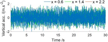
a) In the vertical motion
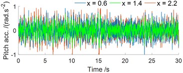
b) In the pitching angle motion
Fig. 4Effect of the battery mass distribution under various velocities of the EV traveling
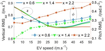
a) RMS acceleration responses of the EV floor
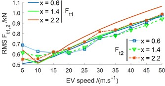
b) RMS force responses at the wheels
A range of the EV’s velocity from 5 to 50 m/s is also simulated to evaluate three cases of the battery mass distribution. The RMS results of the acceleration and force responses of the EV floor and wheels are plotted in Fig. 4(a-b). Observing Fig. 4(a), the battery mass distribution insignificantly affects the vertical EV floor acceleration under three cases of . However, its vertical RMS values are the minimum under the EV's velocity from 20 to 35 m/s. With the pitch RMS results in the same Fig. 4(a), its RMS value is affected not only by the EV’s velocity but also by the battery mass distribution. The pith RMS value is increased following the increase of the EV’s velocity, and pitch RMS value is the minimum in the case of 1.4 m (the battery mass distribution at center of the EV floor). Thus, it can be included that the EV vibration stability is good with the case of 1.4 m and EV’s velocity of 20 to 35 m/s.
Observing Fig. 4(b), the EV’s velocity greatly affects the RMS force responses at the front and rear wheels in all three cases of 0.6, 1.4, and 2.2 m. The RMS value of dynamic force at wheels is small at 5 to 25 m/s and it is quickly increased with increasing the EV’s velocity from 30 to 50 m/s. Therefore, the EV movement safety is reduced when the EV traveling with its high speed from 30 to 50 m/s.
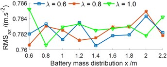
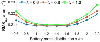
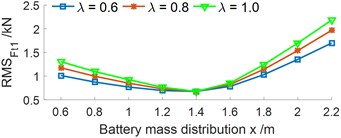
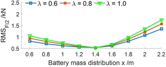
The different distribution of the battery mass {0.6, 0.8, ..., 2.2 m} on the EV floor is also simulated to reach the optimal position of . The simulation results are shown in Figs. 5(a-b). Fig. 5(a) shows that the vertical RMS value is not affected by the battery mass distribution on the EV floor, but the pitch RMS value is strongly affected. The pitch RMS value is the minimum in a range of from 1.2 to 1.4 m. Besides, the vertical RMS value of the wheel dynamic responses with from 0.6 to 1.4 m is significantly small, and it is quickly increased with from 1.5 m to the end, as shown in Fig. 5(b). Therefore, with from 1.2 to 1.4 m, it can remarkably improve the VE movement safety.
A ratio between the battery mass () and the EV body mass {0.6, 0.8, 1.0, 1.2} under {0.6, 0.8, ..., 2.2 m} are also surveyed. The results in Figs. 6(a-b) are shown that the vertical RMS value is not affected by the ratio of while the pitch RMS value is significantly by , the pitch RMS value is increased with increasing the ratio of and vice versa. The results are similar for the vertical RMS force responses at the wheels, as shown in Figs. 6(c-d). The RMS value of the acceleration and force responses are also the minimum at from 1.2 to 1.4 m. Consequently, the ratio of should be bellow 0.6 to improver the EV movement safety.
Fig. 5Effect of the battery mass distribution with the various x values on the EV floor
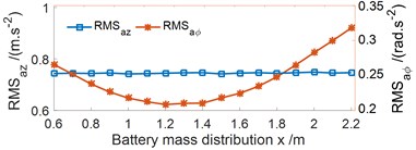
a) RMS acceleration responses of the EV floor
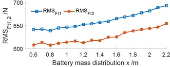
b) RMS force responses at the wheels
Fig. 6Effect of the ratio between the battery mass and EV body mass under the various x values
a) Vertical RMS acceleration of the EV floor
b) Pitch RMS acceleration of the EV floor
c) RMS force responses at the front wheel
d) RMS force responses at the rear wheel
4. Conclusions
Based on the research results of the effect of the battery mass distributions on the EV floor via the numerical simulation under various operation conditions, it can be concluded as follows:
1) The battery mass distribution not affects on the vertical acceleration of the EV floor, but it strongly influences the pitch acceleration of the EV floor.
2) The optimal position of the battery mass distribution is reached with x from 1.2 to 1.4 m on the EV floor and 0.6. It means that the EV movement safety is obviously improved at a range of , especially when the EV travels at the velocity from 20 to 35 m/s (72 to 126 km/h).
3) The research results can be applied to optimize the battery mass and its mass distribution on the EV floor to enhance the vehicle ride comfort apart from improving the EV movement safety. Additionally, the optimal position of the batty mass set-up with its minimum vibration can reduce the vibration and impact between the batteries, therefore, the batteries’ durability can be significantly improved.
References
-
Xiong R., Cao J., Yu Q. Reinforcement learning-based real-time power management for hybrid energy storage system in the plug-in hybrid electric vehicle. Applied Energy, Vol. 211, 2018, p. 538-548.
-
Hung Y., Wu C. A combined optimal sizing and energy management approach for hybrid in-wheel motors of EVs. Applied Energy, Vol. 139, 2015, p. 260-271.
-
Le V., Bui V., et al. Effect of in-wheel motor suspension system on electric vehicle ride comfort. Vibroengineering Procedia, Vol. 29, 2019, p. 148-152.
-
Yu Y., Zhao L., Zhou C. Influence of rotor-bearing coupling vibration on dynamic behavior of electric vehicle driven by in-wheel motor. IEEE Access, Vol. 7, 2019, p. 63540-63549.
-
Ma F., Wang J., Wang Y., Yang L. Optimization design of semi-active controller for in-wheel motors suspension. Journal of Vibroengineering, Vol. 20, Issue 8, 2018, p. 2908-2924.
-
Liu M., Gu F., Zhang Y. Ride comfort optimization of in-wheel-motor electric vehicles with in-wheel vibration absorbers. Energies, Vol. 10, 2017, p. 1647.
-
Liu M., Gu F., Huang J., Wang C., Cao M. Integration design and optimization control of a dynamic vibration absorber for electric wheels with in-wheel motor. Energies, Vol. 10, 2017, p. 2069.
-
Luo Y., Tan D. Study on the dynamics of the in-wheel motor system. IEEE Transactions on Vehicular Technology, Vol. 61, 2012, p. 3510-3518.
-
Tan D., Lu C., Zhang X. Dual-loop PID control with PSO algorithm for the active suspension of the electric vehicle driven by in-wheel motor. Journal of Vibroengineering, Vol. 18, Issue 6, 2016, p. 3915-3929.
-
Arya K., Soheil R., et al. An intelligent cooling system and control model for improved engine thermal management. Applied Thermal Engineering, Vol. 128, 2018, p. 253-263.
-
Choi Y., Lee J., Jang J., Park S. Effects of fuel-injection systems on particle emission characteristics of gasoline vehicles. Atmospheric Environment, Vol. 217, 2019, p. 1-7.
-
Chiong M., Rajoo S., et al. Engine turbocharger performance prediction: One-dimensional modeling of a twin entry turbine. Energy Conversion and Management, Vol. 57, 2012, p. 68-78.
-
Mohamed H., Musa M., Pakharuddin M., et al. Performance comparison between sliding mode control and active force control for a nonlinear anti-lock brake system (ABS). WSEAS Transactions on Systems and Control, Vol. 9, 2014, p. 101-107.
-
Nguyen V., Jiao R., Zhang J. Control performance of damping and air spring of heavy truck air suspension system with optimal fuzzy control. SAE International Journal of Vehicle Dynamics, Stability, and NVH, Vol. 4, Issue 2, 2020, p. 1-16.
-
Van L., Zhang J., Hua W., Wang P. Ride quality evaluation of the soil compactor cab supplemented the auxiliary hydraulic mounts via simulation and experiment, Journal of Southeast University, Vol. 35, Issues 3-2019, 2019, p. 273-280.
-
Mei T., Nguyen V. Control performance of suspension system of cars with PID control based on 3D dynamic model. Journal of Mechanical Engineering, Automation and Control Systems, Vol. 1, Issue 1, 2020, p. 1-10.
Cited by
About this article

This work has been supported by the Scientific and Technology Research Project of Education Department of Hubei Province, China (No. B2019228), and Teaching and Research Project of Hubei Polytechnic University, China (No. 2018C45).
