Abstract
In order to reduce the problem of unsprung mass increased caused by using of in-wheel motor, resulting in poor ride comfort of in-wheel motor drive (IWMD) electric vehicle. A new type in-wheel motor drive electric vehicle vibration reduction system is designed based on the special structure of axial flux motor, and the stator of axial flux motor is suspended by rubber bushing and stator suspension. Then the effectiveness of the designed IWMD electric vehicle vibration reduction system is verified by simulation analysis. The parameters of the designed IWMD electric vehicle vibration reduction system is optimized by orthogonal experiment to further improve which vibration reduction performance, and the optimal parameters scheme of the designed IWMD electric vehicle vibration reduction system is determined by comparative simulation analysis.
1. Introduction
The in-wheel motor drive system simplified transmission system structure, reduce the loss of power in the transmission process, improve the efficiency of the vehicle, and achieve the driving force optimal distribution. However, due to the special driving mode of in-wheel motor, the unsprung mass of the vehicle increases and the ride comfort of the vehicle is reduced [1]. Moreover, unbalanced electromagnetic force is generated due to the change of air gap between the stator and the rotor of the in-wheel motor when vehicle driving on the uneven road, which further deteriorates the ride comfort of the vehicle [2]. Therefore, how to reduce the impact of the increase of unsprung mass and the unbalanced electromagnetic force caused by the change of air gap on vehicle ride comfort is an urgent problem should be solved.
Scholars have extensively researched the design of electric wheel and vibration damping system to reduce the negative influence of the increase of unsprung mass of in-wheel motor. G. Nagaya [3] proposed an Advanced-Dynamic-Damper-Motor (ADM) system, the motor is attached to unsprung mass through a spring and damper of exclusive use, which can make the motor work as a dynamic damper. The ADM system can improve vehicle ride comfort and reduced the vibratory input to the motor. K. M. Rahman [4] made an innovative design for the motor, and the motor stator is connected with the frame to transform the stator mass into sprung mass, which effectively improved the smooth performance of the vehicle. However, the working environment of the motor became more worse, which may reduce the service life of the driving motor. Y. L. Han [5] designed a new type of in-wheel motor electric vehicle wheel. The rubber bushing is added between the stator and the wheel support shaft, to suspend the stator so that it has vibration absorption function. J. H. Huang [6] proposed a vibration-damping system based on the electric wheel, which can realize the transfer of motor mass from unsprung mass to sprung mass, and play the role of dynamic vibration absorber. Y. M. Hu [7] proposed a novel suspension configuration to solve the problem of vibration negative effects caused by in-wheel motor, which combining dynamic damping and active suspension. And a multi-objective particle swarm optimization linear quadratic regulator is designed to optimize the parameters of the new suspension. H. Z. Ren [8] designed an in-wheel motor suspension system, which can be installed in the electric wheel to reduce the negative effect of vertical vibration caused by the increase of sprung mass of electric vehicle driven by in-wheel motor. The design concept is to arrange a set of rubber bushing in the electric wheel, realize the elastic isolation of motor mass and other unsprung masses, associate part of unsprung mass with vehicle body, and absorb part of the vibration transmitted to the electric wheel caused by road excitation. P. P. Zhao [9] put forward a new in-wheel motor drive model (NIWMD), the in-wheel motor and the electromagnetic damper constitute a dynamic vibration absorber, and studied the influence of NIWMD system parameters on vertical performance evaluation indexes of IWMD vehicle. X. B. Chen [10] apply the principle of adaptive transmission to enable propulsion motor to work as the dynamic vibration absorber to suppress the unsprung mass vibration. The research direction of vibration reduction system of electric vehicle driven by in-wheel motors is mainly based on traditional radial motors, and the change of motor air gap caused by vibration can be reduced by optimizing motor structure or control strategy [11, 13], so as to achieve the corresponding vibration reduction effect.
However, there are few researches on using the special structure of axial flux motor to design the vibration reduction system of IWMD electric vehicle, so as to reduce the problem of deterioration of vehicle ride comfort due to the increase of unsprung mass caused by using of in-wheel motor. Therefore, new vibration reduction system is designed based on axial flux motor, the parameters of new vibration reduction system is optimized by orthogonal experiment. Finally, the optimal parameters scheme of new vibration reduction system is obtained to make the IWMD electric vehicle have good ride comfort.
2. Design and analysis of IWMD electric vehicle vibration reduction system
In order to reduce the influence of the increase of unsprung mass caused by using of in-wheel motor and the unbalanced electromagnetic force caused by the change of air gap of drive motor on vehicle ride comfort, it is necessary to redesign the configuration of IWMD electric vehicle vibration reduction system.
2.1. Design of new vibration reduction system
When using in-wheel radial motor as the power plant of IWMD electric wheel, the unsprung mass will increase, and unbalanced electromagnetic force will be generated by the change of the air gap between the stator and rotor of radial motor during the driving process. The increase unsprung mass and the normal component of the unbalanced electromagnetic force will deteriorate the vehicle ride comfort [14]. In order to solve above problems, axial flux motor is used to reduce the generation of normal unbalanced electromagnetic force, and the motor vibration reduction system is designed. The designed structure of new vibration reduction system is shown in Fig. 1.
As shown in Fig. 1, rotor 2 is connected to hub 1 through flange construction, stator 3 is suspended by rubber bushing 4 and stator suspension 7, rotor 2 is connected to motor shaft 5 and stator 3 respectively through bearings 8 and 9, and vehicle suspension 6 is connected to motor shaft 5.
2.2. Dynamics modeling of 1/4 vehicle
In order to simplify the vehicle vibration model into 1/4 vehicle vibration model to analyze the vertical vibration performance of the IWMD electric vehicle, sprung mass, suspension equivalent stiffness and damping, road unevenness are assumption symmetric distribution with the longitudinal axial symmetrical of vehicle. The 1/4 vehicle vibration models are shown in Fig. 2.
Fig. 1Structure of new vibration reduction system: 1 – hub; 2 – rotor; 3 – stator; 4 – rubber bushing; 5 – motor shaft; 6 – vehicle suspension; 7 – stator suspension; 8 – bearing; 9 – bearing
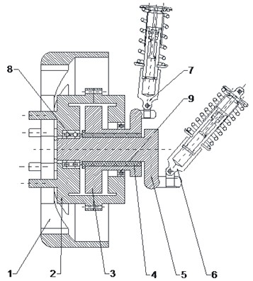
Fig. 21/4 vehicle vibration models
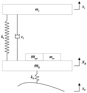
a) With traditional vibration reduction system
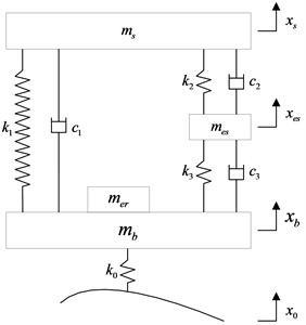
b) With new vibration reduction system
Based on the Newton laws, the 1/4 vehicle vibration model of IWMD electric vehicle with traditional vibration reduction system can be formulated as:
The 1/4 vehicle vibration model of IWMD electric vehicle with new vibration reduction system can be formulated as:
where, is 1/4 sprung mass; is wheel assembly mass(include wheel mass and motor shaft mass ); is stator mass; is rotor mass; is tire stiffness; is vehicle suspension stiffness; is vehicle suspension damping; is stator suspension stiffness; is stator suspension damping; is rubber bushing stiffness; is rubber bushing damping; is the road input to the tire; is the vertical displacement of tire; is the vertical displacement of stator; is the vertical displacement of sprung mass.
Eq. (2) can be written into matrix form as:
where, is the mass matrix, is the damping matrix, is the stiffness matrix:
The Laplace transform of Eq. (2) can be formulated as:
In order to simplify Eq. (7), set , , , , , .
The amplitude-frequency response function of the vertical displacement of sprung mass to the vertical displacement of tire is obtained by solving Eq. (7):
The amplitude-frequency response function of the vertical displacement of sprung mass to the vertical displacement of road is:
The amplitude-frequency response function of the vertical displacement of wheel to the vertical displacement of road is:
The amplitude-frequency response function of the vertical displacement of stator to the vertical displacement of road is:
As for the IWMD electric vehicle with new vibration reduction system, the amplitude-frequency characteristics of sprung mass vertical acceleration (SVA), vehicle suspension dynamic deflection (VSDD), tire dynamic load (TDL) and stator mass vertical acceleration (SMVA) are as follows:
2.3. Dynamic analysis
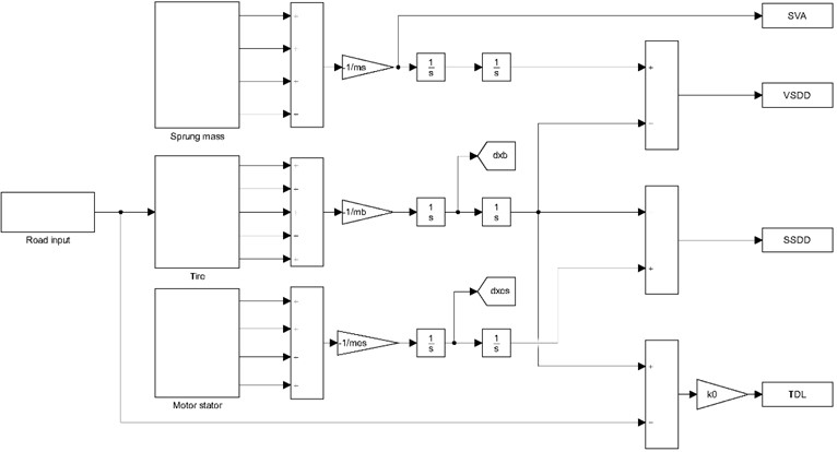
In order to analyze the effectiveness of the designed new vibration reduction system, Simulink models of the 1/4 vehicle vibration model of IWMD electric vehicle with traditional vibration reduction system and with new vibration reduction system are established respectively. The established Simulink model of the 1/4 vehicle vibration model of IWMD electric vehicle with new vibration reduction system is shown in Fig. 3.
Fig. 3Simulink model of the 1/4 vehicle vibration model of IWMD electric vehicle with new vibration reduction system
The simulation road is set as B-level, vehicle speed is set as 10 m/s, and simulation time is set as 10 s. The key parameters of simulation are shown in Table 1.
The dynamic time domain responses of the IWMD electric vehicle with traditional vibration reduction system and with new vibration reduction system are shown in Fig. 4.
As can be seen from Fig. 4, when the IWMD electric vehicle driving on B-level road with speed of 10 m/s, the SVA and TDL of the vehicle with new vibration reduction system decrease significantly compared with the vehicle with traditional vibration reduction system, and the VSDD of the vehicle with new vehicle vibration reduction system is optimized to a certain extent although the amplitude changes little.
Table 1Key parameters of simulation
Symbol | Unit | Value |
kg | 260 | |
kg | 15 | |
kg | 25 | |
kg | 15 | |
N/m | 23094 | |
N/m | 15000 | |
N/m | 10000 | |
N⋅s/m | 1761 | |
N⋅s/m | 1650 | |
N⋅s/m | 1000 |
Fig. 4Comparison of time-domain response between different vibration reduction systems
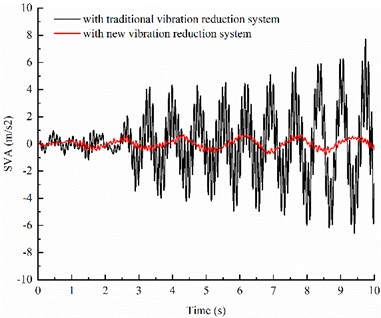
a) SVA
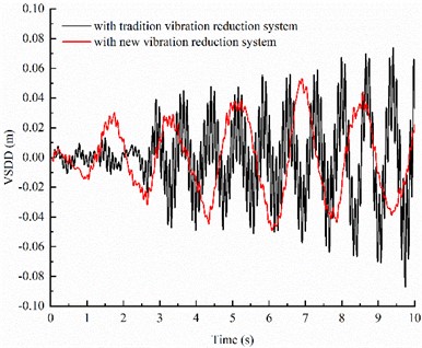
b) VSDD
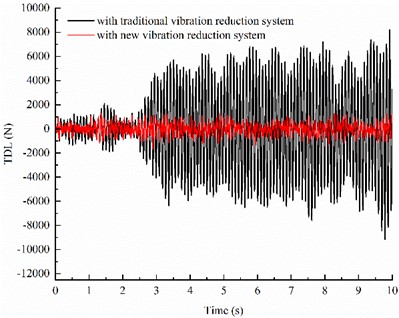
c) TDL
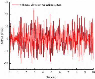
d) SMVA
The RMS values of four evaluation indexes of time-domain response under B-level road are shown in Table 2.
As can be seen from Table 2, when the IWMD electric vehicle is driving on B-level road with speed of 10 m/s, the RMS values of four evaluation indexes of time-domain response under B-level road of the vehicle with new vibration reduction system is smaller than that of the IWMD electric vehicle with new vibration reduction system, which means that the designed new vibration reduction system can significantly improving vehicle ride comfort.
The dynamic frequency domain responses of the IWMD electric vehicle with traditional vibration reduction system and with new vibration reduction system are shown in Fig. 5.
Table 2RMS values of four evaluation indexes
Evaluation indexes | With tradition vibration reduction system | With new vibration reduction system |
SVA | 2.3324 | 0.2374 |
VSDD | 0.0263 | 0.0185 |
TDL | 3424 | 464 |
SMVA | – | 7.7277 |
Fig. 5Comparison of frequency domain responses between different vibration reduction systems
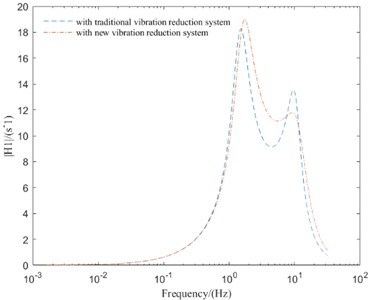
a) SVA
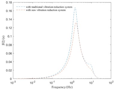
b) VSDD
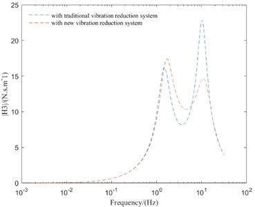
c) TDL
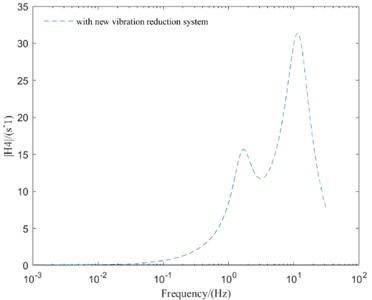
d) SMVA
As can be seen from Fig. 5, compared with the IMWD electric vehicle with tradition vibration reduction system, the IMWD electric vehicle with new vibration reduction system can well suppress the peak values of vibration response and improve the vehicle vertical performance in the high-frequency resonance region. But in the low-frequency resonance region and mid-frequency resonance region, the peak values of vibration response of IMWD electric vehicle with new vibration reduction system are lager then that with tradition vibration reduction system. So, it is necessary to optimize the parameters of the designed new vibration reduction system to make the designed new vibration reduction system has better vibration reduction effect in all frequency region.
3. Parameter optimization of new in-wheel motor drive electric vehicle vibration reduction system
The vehicle ride comfort evaluation indexes with the preliminarily selected parameters of new vibration reduction system have been greatly improved, but has not been achieved ideal effect. So, it is necessary to optimize the parameters of new vibration reduction system. However, there are so many parameters of the designed new vibration reduction system, it’s difficult to optimized theses parameters simultaneously by traditional methods.
The multi-factor experiment of orthogonal experimental design can experiment multiple factors at the same time, and obtain more comprehensive and accurate experimental results [15-17]. Therefore, based on the conclusion of single factor analysis, the parameters of the new vibration reduction system are optimized by orthogonal experimental method.
3.1. Determine factor level and optimize objective
In order to improve the performance of the designed new vibration reduction system, vehicle suspension stiffness , vehicle suspension damping , stator suspension stiffness , stator suspension damping , rubber bushing stiffness , rubber bushing damping and vehicle speed are selected as factors. The orthogonal experimental method is used to optimize four evaluation indexes of SVA, VSDD, TDL and SMVA. The designed factors and levels are shown in Table 3.
Table 3Designed factors and horizontal levels
Factor | Level 1 | Level 2 | Level 3 | Level 4 | Level 5 | Level 6 | Level 7 |
15000 | 19000 | 23000 | 27500 | 29500 | 31500 | 33500 | |
4500 | 8000 | 11500 | 15000 | 18500 | 22000 | 25500 | |
4500 | 8000 | 11500 | 15000 | 18500 | 22000 | 22500 | |
1100 | 1300 | 1500 | 1700 | 1900 | 2100 | 2300 | |
400 | 600 | 800 | 1000 | 1200 | 1400 | 1600 | |
250 | 300 | 350 | 400 | 450 | 500 | 550 | |
10 | 15 | 20 | 25 | 30 | 35 | 40 |
Orthogonal optimization experiment is used to optimize the parameters of new vibration reduction system, in order to obtain the optimization parameters more accurately, multi-objective optimization method is adopted.
In the orthogonal optimization experiment, besides taking the RMS values of SVA, VSDD TDL and SMVA as evaluation index, the comprehensive evaluation index is designed and used. The comprehensive optimization objective is the synthesis of the evaluation indexes of vehicle ride comfort [18], and which expression is as follows:
where, , , and are respectively the RMS values of the four evaluation indexes, SVA, VSDD, TDL and SMVA, which are obtained by orthogonal experimental of the new vibration reduction system. , , , are RMS values of the four evaluation indexes before orthogonal experiment. , , , are the weighting coefficient of each factor, and . Since the main goal of the new vibration reduction system is to reduce SVA, therefore the weighting coefficients of each factor are set as , , , respectively.
3.2. Selection and experiment of orthogonal table
As can be seen from Table 3, orthogonal experiment with seven factors and seven levels is adopt in this paper but the orthogonal table with seven factors and seven levels is not commonly used. Therefore, orthogonal table with eight factors and seven levels is used as the orthogonal test table, and all factors and levels are reorganized. The schemes of each orthogonal experiment are determined as shown in Fig. 6.
Fig. 6Determined schemes of each orthogonal experiment
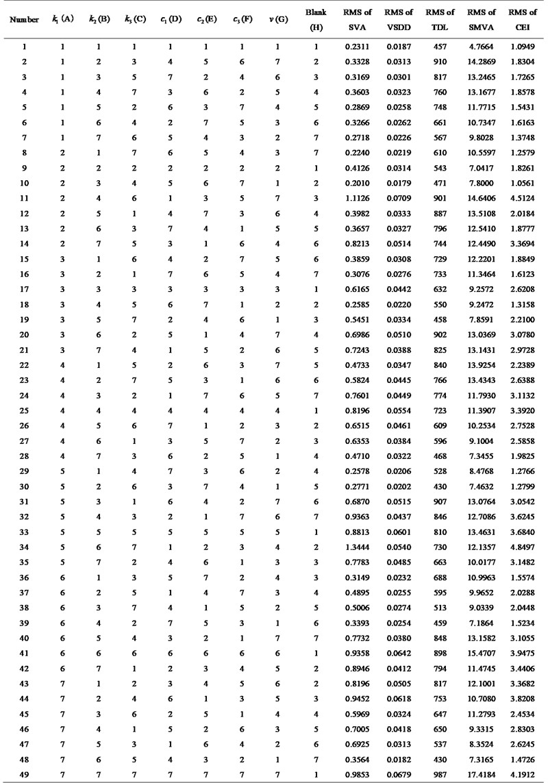
In Fig. 6, numbers 1, 2, 3, 4, 5, 6 and 7 respectively represent different levels set by each factor in Table 3. Simulation tests are carried out one by one according to all the data in Fig. 6 and the simulation results and calculation results of each orthogonal experiment are obtained.
3.3. Range analysis of orthogonal test
In order to obtain the influence of different factors on vehicle ride comfort, range analysis of the results obtained by orthogonal experiment is carried out.
The mutual influence of different parameters of new vibration reduction system on vehicle ride comfort is ignored, then six groups of parameters combination scheme are obtained through the results of Fig. 6. Simulations of 1/4 vehicle vibration model of IWMD electric vehicle with new vibration reduction system with six groups of parameters combination scheme are carried out respectively, and RMS values of four evaluation indexes are obtained. Finally, compared the RMS values of four evaluation indexes under six groups of parameters combination scheme with the RMS values of four evaluation indexes before orthogonal experiment to determine whether the vehicle ride comfort is improved. The RMS values of four evaluation indexes of different parameters combination scheme is shown in Table 4.
Table 4RMS values of four evaluation indexes of different parameters combination scheme
Parameters combination scheme | RMS of SVA | RMS of VSDD | RMS of TDL | RMS of SMVA |
Before optimization | 0.2374 | 0.0185 | 464 | 7.7277 |
Scheme 1 (A1B1C5D7E7F2G1) | 0.1825 | 0.0276 | 447 | 7.3245 |
Scheme 2 (A1B1C3D2E7F1G1) | 0.1521 | 0.0152 | 442 | 6.5165 |
Scheme 3 (A4B1C6D2E2F1G1) | 0.5075 | 0.0323 | 408 | 6.4314 |
Scheme 4 (A3B1C1D1E1F1G1) | 0.5033 | 0.0301 | 464 | 4.78 |
Scheme 5 (A1B4C7D4E5F1G1) | 0.2047 | 0.0189 | 437 | 7.3786 |
Scheme 6 (A1B1C5D7E7F2G1) | 0.1825 | 0.0276 | 447 | 7.3245 |
As can be seen from Table 4, since the main objective of the designed new vibration reduction system is to reduce SVA to improve vehicle ride comfort, therefore parameters combination scheme 1 (same as parameters combination scheme 6), parameters combination scheme 2 and parameters combination scheme 5 are better.
4. Analysis the vibration reduction performance of different parameters combination schemes
Combined with Eq. (12-15), the amplitude-frequency characteristic curves of each evaluation index of vehicle ride comfort under different parameters combination schemes can be obtained by MATLAB.
4.1. Comparative analysis of parameters combination schemes
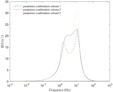
In order to finally determine the optimal parameters combination scheme of new vibration reduction system, the vehicle driving simulation on B-class road with the vehicle speed of 10 m/s is carried out, and the simulation results are shown in Fig. 7.
As can be seen from Fig. 7, the parameters combination scheme 1 greatly improves the amplitude-frequency response of the new vibration reduction system, and the amplitudes of each evaluation index decrease correspondingly. The parameters combination scheme 2 reduce the amplitude of SVA and SMVA, but the amplitude of suspension dynamic deflection and TDL are worsened. The parameters combination scheme 5 reduce the amplitude of SVA and TDL, but the amplitude of suspension dynamic deflection and SMVA are worsened.
According to the above analysis, both parameters combination scheme 2 and parameters combination scheme 5 can reduce the amplitude of SVA, but the amplitude other three evaluation indexes are not optimal. However, parameters combination scheme 1 can make the amplitude of four evaluation indexes in a better range. Therefore, parameters combination scheme 1 can improve the comprehensive performance of the vehicle with new in-wheel motor drive electric vehicle vibration reduction system.
Fig. 7Frequency domain responses of different parameters combination schemes
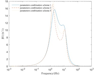
a) SVA
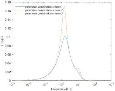
b) VSDD
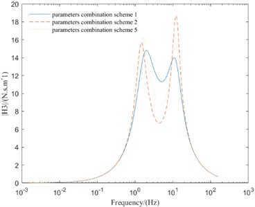
c) TDL
d) SMVA
4.2. Determine optimal parameters of new in-wheel motor drive electric vehicle vibration reduction system
After simulation comparative analysis of vehicle ride comfort of six parameters combination schemes, it can be concluded that parameters combination scheme 1 is the optimal parameters combination scheme. Then, the parameters of new vibration reduction system are shown in Table 5.
Table 5The optimal parameters of new vibration reduction system
Parameter | Parameter symbol | Unit | Value |
Vehicle suspension stiffness | N/m | 15000 | |
Stator suspension stiffness | N/m | 4500 | |
Rubber bushing stiffness | N/m | 18500 | |
Vehicle suspension damping | N⋅s/m | 2300 | |
Stator suspension damping | N⋅s/m | 1600 | |
Rubber bushing damping | N⋅s/m | 300 |
5. Conclusions
Based on the structure of axial flux motor, a new type of IWMD electric vehicle vibration reduction system with stator suspended is designed. The different parameters combination schemes of the new vibration reduction system are obtained based on orthogonal experiment. Finally, the optimal parameters combination scheme is obtained by simulation comparative analysis.
References
-
F. Lei, Y. Bai, W. Zhu, and J. Liu, “A novel approach for electric powertrain optimization considering vehicle power performance, energy consumption and ride comfort,” Energy, Vol. 167, pp. 1040–1050, Jan. 2019, https://doi.org/10.1016/j.energy.2018.11.052
-
Z. Deng, X. Li, T. Liu, and S. Zhao, “Modeling and suppression of unbalanced radial force for in-wheel motor driving system,” Journal of Vibration and Control, Vol. 28, No. 21-22, pp. 3108–3119, Nov. 2022, https://doi.org/10.1177/10775463211026041
-
G. Nagaya, “Development of an in-wheel drive with advanced dynamic-damper mechanism,” JSAE Review, Vol. 24, No. 4, pp. 477–481, Oct. 2003, https://doi.org/10.1016/s0389-4304(03)00077-8
-
K. M. Rahman, N. R. Patel, T. G. Ward, J. M. Nagashima, F. Caricchi, and F. Crescimbini, “Application of direct-drive wheel motor for fuel cell electric and hybrid electric vehicle propulsion system,” IEEE Transactions on Industry Applications, Vol. 42, No. 5, pp. 1185–1192, Sep. 2006, https://doi.org/10.1109/tia.2006.880886
-
Y. L. Han, G. S. Li, Q. Wang, and K. D. He, “Ride comfort of a new in-wheel motor driving electric vehicle based on the negative effect of vertical vibration,” (in Chinese), Science Technology and Engineering, Vol. 19, No. 16, pp. 363–369, 2019.
-
J. H. Huang, J. Yang, M. C. Liu, and M. Cao, “Integrated design, parameter matching and optimal control of the vibration-damping system based on the electric wheel,” (in Chinese), Journal of Machine Design, Vol. 36, No. 9, pp. 14–20, 2019.
-
Y. M. Hu, Y. N. Li, Z. Li, and C. Yang, “Multi-objective particle swarm optimal control based on integrated active and passive suspension architecture,” (in Chinese), Control Theory and Applications, Vol. 37, No. 3, pp. 574–583, 2020.
-
H. Z. Ren, S. Chen, and Y. H. Zhang, “Design and optimization of wheel inner mount system for electric vehicle with hub motor,” (in Chinese), Science Technology and Engineering, Vol. 22, No. 10, pp. 4170–4179, 2022.
-
P. Zhao and Z. Fan, “Design, modeling, and research on vertical performance of a drive system with in-wheel motor as dynamic vibration absorber,” Proceedings of the Institution of Mechanical Engineers, Part D: Journal of Automobile Engineering, Vol. 237, No. 4, pp. 862–877, Mar. 2023, https://doi.org/10.1177/09544070221078360
-
X. Chen, A. Kong, and W. Wang, “In-wheel drive system design with dynamic vibration absorption based on the adaptive transmission mechanism,” Proceedings of the Institution of Mechanical Engineers, Part D: Journal of Automobile Engineering, p. 095440702311722, May 2023, https://doi.org/10.1177/09544070231172237
-
J. Huang, Y. Liu, M. Liu, M. Cao, and Q. Yan, “Multi-objective optimization control of distributed electric drive vehicles based on optimal torque distribution,” IEEE Access, Vol. 7, pp. 16377–16394, 2019, https://doi.org/10.1109/access.2019.2894259
-
Z. Li and L. Zheng, “Integrated design of active suspension parameters for solving negative vibration effects of switched reluctance-in-wheel motor electrical vehicles based on multi-objective particle swarm optimization,” Journal of Vibration and Control, Vol. 25, No. 3, pp. 639–654, Feb. 2019, https://doi.org/10.1177/1077546318791023
-
Y. Zhu, C. Zhao, J. Zhang, and Z. Gong, “Vibration control for electric vehicles with in-wheel switched reluctance motor drive system,” IEEE Access, Vol. 8, pp. 7205–7216, 2020, https://doi.org/10.1109/access.2020.2964582
-
Y. Hu, Y. Li, Z. Li, and L. Zheng, “Analysis and suppression of in-wheel motor electromagnetic excitation of IWM-EV,” Proceedings of the Institution of Mechanical Engineers, Part D: Journal of Automobile Engineering, Vol. 235, No. 6, pp. 1552–1572, May 2021, https://doi.org/10.1177/0954407020979096
-
J. H. Dong and A. G. Cheng, “Optimization and matching of mini passenger car suspension parameters based on design of experiment,” (in Chinese), Science and Technology Review, Vol. 28, No. 14, pp. 75–79, 2010.
-
T. Feng and L. Shu, “Game-based multiobjective optimization of suspension system for in-wheel motor drive electric vehicle,” Mathematical Problems in Engineering, Vol. 2021, pp. 1–13, Apr. 2021, https://doi.org/10.1155/2021/5589199
-
R. M. Desai, M. E. H. Jamadar, H. Kumar, S. Joladarashi, and S. C. Raja Sekaran, “Design and experimental characterization of a twin-tube MR damper for a passenger van,” Journal of the Brazilian Society of Mechanical Sciences and Engineering, Vol. 41, No. 8, pp. 1–21, Aug. 2019, https://doi.org/10.1007/s40430-019-1833-5
-
G. Hu, L. Wu, Y. Deng, L. Yu, and G. Li, “Optimal design and performance analysis of magnetorheological damper based on multiphysics coupling model,” Journal of Magnetism and Magnetic Materials, Vol. 558, p. 169527, Sep. 2022, https://doi.org/10.1016/j.jmmm.2022.169527
Cited by
About this article

We would like to acknowledge financial support from the Jiangxi Province College Students Innovation and Entrepreneurship Training Program (Grant Numbers: 202110407016).
The datasets generated during and/or analyzed during the current study are available from the corresponding author on reasonable request.
Lunzuo Li: formal analysis; Sheng Kang: methodology; JiangJun Deng: writing-original draft.
The authors declare that they have no conflict of interest.
