Abstract
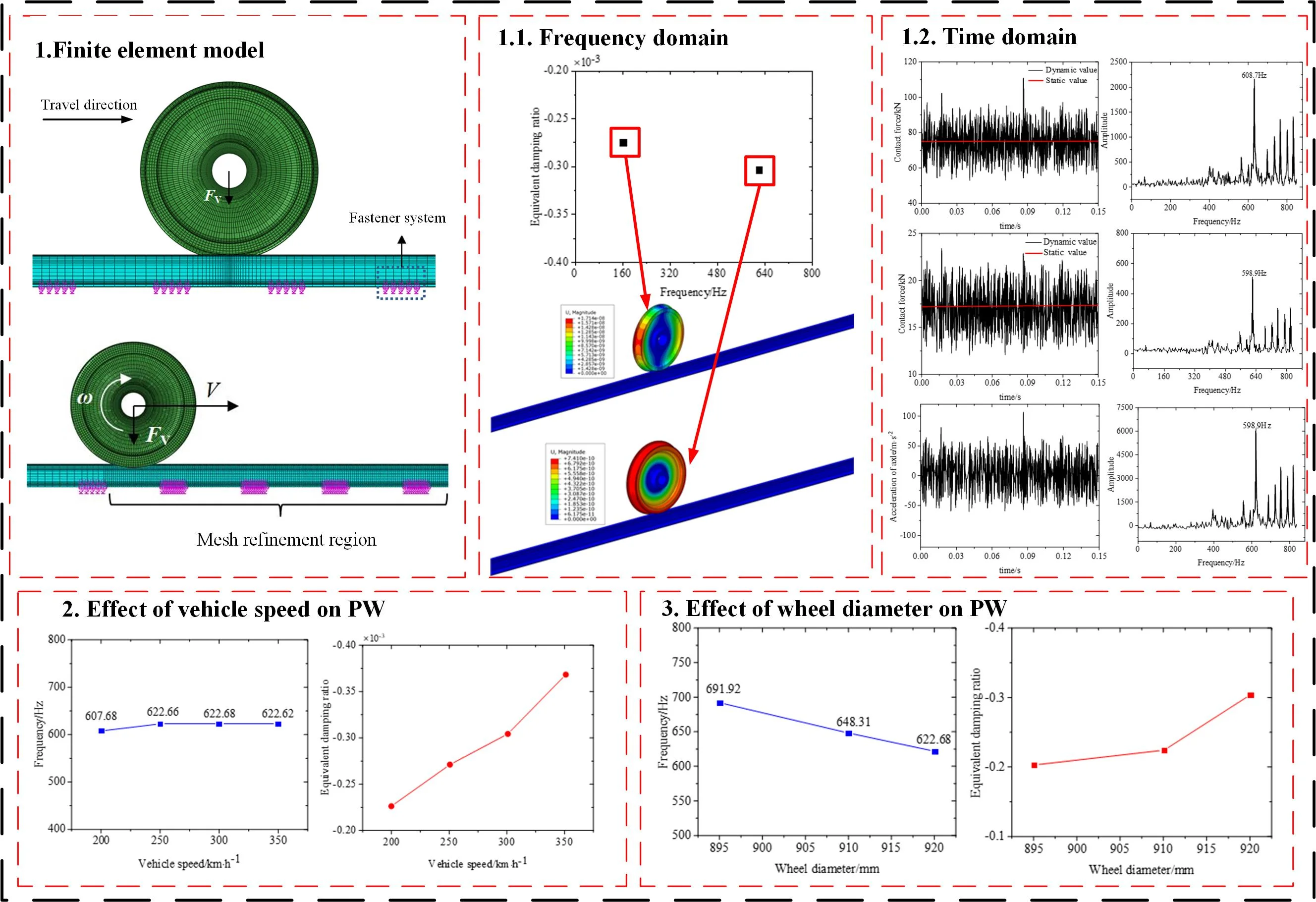
High-order polygonal wear of wheels is one of the most severe technical challenges for China's high-speed trains at present, and its formation mechanism has not been thoroughly understood. The effect of train traction on the wheel polygonal wear of high-speed trains was studied based on a wheel/rail rolling contact finite element model. The frequency domain characteristics of unstable vibration of the wheel/rail system under rolling/sliding contact were studied by using the finite element complex modal analysis method. We also examined wheel/rail contact forces and friction in the time domain. The cause of the high-order polygonal wear of Chinese high-speed train wheels was revealed. The effect of the vehicle speed and the wheel diameter on wheel polygonal wear were investigated. The results show: the friction-induced vibration of the wheel/rail system will be excited when the rolling/sliding contact between the wheel and rail. The radial zoom modal of the wheel is an unstable mode, which is the main cause of the 21-22 order polygonal wear of the high-speed train wheels in China. Additionally, vehicle speed has a linear relationship with the order of polygonal wear. Reducing the vehicle speed helps to control the polygonal wear of the wheels. Wheels of different diameters exhibit varying degrees of polygonal wear, with smaller wheels being more resistant to friction-induced vibrations.
Highlights
- The friction-induced vibrations are the primary driver of high-order polygonal wear.
- Vehicle speed has a linear relationship with polygonal wear order, and higher speeds lead to more severe polygonal wear.
- Larger wheel diameters are associated with a higher likelihood of friction-induced vibration occurrence and more pronounced polygonal wear.
1. Introduction
Polygonal wear (hereinafter referred to as PW) of wheels, is one of the most severe technical challenges for the high-speed railway in China at present. PW of wheels will lead to severe vibration and noise radiation of the wheel-rail system (hereinafter referred to as WRS). According to investigations, the vibration acceleration on the axle box can reach 40 g [1] for wheels with PW. Under such intense vibration, the axle box cover is prone to become loose and fall off, which generates safety hazards. The forced vibration induced by PW of wheels can also lead to fatigue failure between components of the WRS, such as breaking of axle box cover bolts, breaking of clips on rail fasteners, breaking of gearboxes, and breaking of wheelset suspensions [2]. In addition, PW of wheels increases the interior and exterior noise levels by 8-11 dBA [3, 4], which affects passengers’ riding experience and normal life of residents along the railway line.
When PW develops to a certain degree, reprofiling becomes necessary to eliminate the PW layer. However, reprofiling substantially escalates the operating costs of high-speed trains. Moreover, due to the shaping impact of reprofiling equipment, certain orders of PW cannot be completely removed [5]. Meywerk [6] studied the formation mechanism of PW of wheels based on wear theory. The study revealed that external irregularities trigger the first-order and secondary bending patterns of the wheelset, which are crucial in the formation of PW of wheels. Morys et al. [7] studied the evolution process of initial PW of different orders on German ICE-1 trains in accordance with the dynamic response model of WRS and the cyclic theory of material wear. Theoretical calculations demonstrated that the vertical bending vibration of wheelset, induced by initial wheel irregularity, represents a significant cause underlying PW of wheels. Rode et al. [8] studied the generation of third-order PW of wheels is related to the third-order initial non-circularity resulting from the three-jaw clamping method during wheel manufacturing. Nielson et al. [9] considered the thermomechanical coupling effect of train brake shoe braking as an important inducement for PW of wheels. Fröhling et al. [10, 11] found that under saturated adhesion, the self-induced stick-slip vibrations of the WRS and the torsional vibration of wheelset are important causes for the PW of locomotive wheels the development of PW on locomotive wheels within the context of South Africa. Peng et al. [12] also considered that under small radius curves or substantial traction torque, the occurrence of stick-slip vibrations at the wheel-rail interface is a significant factor contributing to PW of wheels. Jin et al. [13, 14] found that the 9th order PW observed on metro wheels originated from the 1st order bending vibration of wheelsets. They suggested enhancing the bending stiffness of wheelsets by implementing measures such as increasing the diameter of wheel axles, so as to suppress such PW. The field tests and modal analysis by Tao et al. [15, 16] revealed that the primary cause of the 5th to 8th order PW on metro wheels was the P2 resonance. Chen et al. [17, 18] and Zhao et al. [19, 20] found that sliding contact between wheel and rail tends to initiate friction-induced vibration (hereinafter referred to as FIV) in the WRS, leading to the occurrence of PW of high-speed train wheels. Wu et al. [21, 22] pointed out that the coupled effect of FIV of disc brakes and WRS can lead to high-order PW of high-speed train wheels. Wu et al. [23, 24] found that the 22nd and 23rd order PW of high-speed train wheels originated from the coupled resonance between bogies and wheelsets. Ma et al. [25] suggested in their theoretical analysis that local third-order bending vibration of rails could cause high-order PW.
The current theories of FIV, coupled resonance between bogies and wheelsets, and local bending vibration of rails [26] cannot sufficiently explain the characteristics and patterns of high-order PW on high-speed train wheels. For instance, the theories of modal coupling resonance of bogies and local bending vibration of rails believe that the resonance of WRS induced by external irregularities leads to PW of wheels, while neglecting the effect of inherent instability of WRS on PW. While FIV mechanism focuses on the impact of saturated creep force between wheel and rail during high-speed train braking on PW, the relationship between FIV of WRS and PW under high-speed train driving condition remains unreported.
2. Numerical simulation model of PW on high-speed train wheels
2.1. Finite element model
China's high-speed trains operate at high velocities, and the adhesion coefficient at the wheel-rail interface decreases continuously as the speed increases. Therefore, the creep force at the wheel-rail interface readily achieves a saturated state during driving and acceleration of high-speed trains. The saturated creep force is inclined to excite FIV in the WRS [27], thereby leading to the creation of cyclic uneven wear at the wheel-rail contact region [27, 17]. A finite element model of the WRS under rolling-sliding condition was established. Modal analysis was utilized to study the frequency-domain attributes of FIV in the WRS. The motion equations of the WRS were solved by implicit time integration method. The interplay between FIV of the WRS and the formation of PW on wheels was investigated to reveal the mechanism of PW on the wheels of high-speed trains in China. Fig. 1 illustrates the finite element model utilized for frequency domain analysis of PW on wheels. Complex eigenvalue analysis was conducted based on this model to analyze the vibration modes of FIV under saturated tangential force at the wheel-rail interface. To reduce computational cost, the model only included a single side of the wheel and rail, and the impact of axle was ignored. The nominal diameter of the wheel was 920 mm. The vertical suspension force, denoted as , was substituted for the sprung mass in the model. The rail length measured 36,252 mm, about 56 times of the fastener spacing. The rail cant was 1/40. The rail was discreetly supported by ground springs and damping units replacing the fastener system. The spacing between adjacent fasteners was 650 mm, and the support length of each fastener was 130 mm [28]. The normal contact interaction at the wheel-rail interface was described using a face-to-face contact algorithm employing the penalty method. Coulomb law of friction was applied to characterize tangential contact behavior. The normal contact behavior at the wheel-rail interface was represented using the hard contact algorithm. To simulate the rolling process on a straight track, translation and rotational velocities were imparted to the wheel, ensuring that the wheelset's lateral displacement and yaw angle remained nearly negligible. Consequently, the lateral and rotational creepages at the wheel-rail interface can be regarded as zero. Consequently, only the longitudinal creepage at the wheel-rail interface was considered in the model. The displacement boundary conditions in the model were: the translational degrees of freedom in three directions at both ends of the rail was restricted. Meanwhile, all degrees of freedom of the nodes on the axle surface were coupled to a reference point on the wheel axis, with only the vertical degree of freedom of this reference point left unconstrained. The wheel and rail were discretized using incompatible hexahedral elements. Dense mesh was applied at the wheel-rail contact interface, while coarse mesh was used away from the contact interface. The model consists of a total of 111,040 solid elements and 135,570 nodes.
The dynamic response of the WRS was obtained through an explicit dynamic analysis and explore the time-domain traits of FIV in the WRS. Fig. 2 shows the established finite element model for time-domain analysis of PW on wheels. The dynamic response of WRS was determined using the implicit time integration method. In the dynamic model, the wheel rolled on the rail, and refined mesh was applied to the rail sections in contact with the wheel. The displacement boundary conditions for the wheel were: only the vertical, longitudinal translational degrees of freedom and rotational degree of freedom were retained. Other mechanical and displacement boundary conditions were consistent with the complex eigenvalue analysis model. The material parameters are listed in Table 1, and other relevant parameters are given in Table 2, the data for the coefficient of friction and stiffness, damping, and other important parameters were sourced from commonly used fastening systems in high-speed railways [29]. Typically, the wheel-rail coefficient of friction decreases with increasing train speed. At speeds around 300 km/h, the coefficient of friction in normal adhesion conditions is approximately 0.23. And we set the longitudinal creepage at 0.7 %, which can lead to a saturation of creep forces at the wheel-rail interface [22].
The transient dynamic response of the WRS is computed using the implicit time integration method through the following steps: (1) Apply the vertical suspension force for static stress analysis; (2) Apply translation and rotation velocities to the wheel to simulate the rolling-sliding motion of the wheel.
Fig. 1Finite element model of the frequency domain analysis of the wheel PW
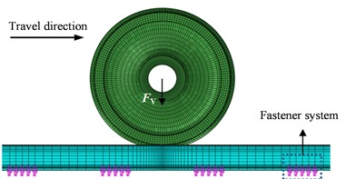
Fig. 2Finite element model of the time domain analysis of the wheel PW
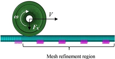
Table 1Material parameters
Elastic modulus (MPa) | Poisson’s ratio | Density (kg/m3) | |
Wheel | 205000 | 0.3 | 7800 |
Rail | 210000 | 0.3 | 7800 |
Table 2Other parameters
Parameter | Value | |
Vehicle speed (km/h) | 300 | |
Coefficient of friction | 0.23 | |
Longitudinal creepage (%) | 0.7 | |
Fastener stiffness | Vertical stiffness (MN/m) | 50 |
Lateral stiffness (MN/m) | 28 | |
Fastener damping | Vertical damping (kN·s/m) | 30 |
Lateral damping (kN·s/m) | 20 | |
2.2. Complex eigenvalue analysis method
The equations of motion for the WRS can be established:
where , and represent the mass, damping and stiffness matrices of the WRS, respectively. , and denote the acceleration, velocity and displacement vectors of the nodes, respectively. The equation of motion Eq. (1) has the following characteristic equation:
where, signifies the eigenvalue, and represents the eigenvector,
Due to the saturated creep force at the wheel-rail interface, the damping and the stiffness matrices of the system are asymmetric matrices. Eq. (2) has complex eigenvalues, which can be resolved using the subspace projection method to obtain the solution of Eq. (2), and further the solution of Eq. (1):
where is the k-order eigenvalue of the system. When the real part of the eigenvalue is positive, the system’s vibration will undergo exponential growth over time, resulting in instability. The equivalent damping ratio (hereinafter referred to as EDR) is generally used to evaluate the trend of instability. The system will become unstable and FIV will occur in the WRS when the EDR is negative.
2.3. Analysis of PW on wheel
The friction-wear model developed by Brockley [30] can qualitatively explain the correlation between FIV of the WRS and the formation of PW on wheels:
where denotes the volumetric wear rate, signifies the material wear constant, denotes the friction power between wheel and rail (, where is the tangential force at the wheel-rail interface, and v represents the sliding velocity at the wheel-rail interface). is the endurance frictional power, which is a constant. Under rolling-sliding condition, the tangential force at the wheel-rail interface , where is the normal contact force, and is the friction coefficient. Therefore, the wear rate exhibits a proportional relationship with the normal contact force . If FIV of the WRS leads to oscillations of the normal contact force , the wear rate will also fluctuate accordingly, resulting in periodic non-uniform wear of the wheel tread, eventually leads to the polygonization of the wheel.
3. Numerical simulation of PW on high-speed train wheels
3.1. Frequency domain
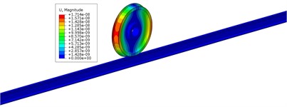
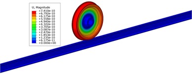
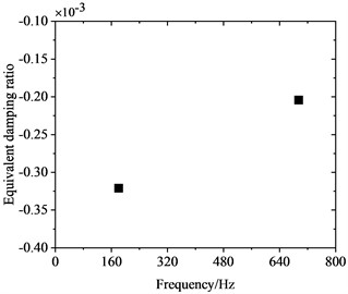
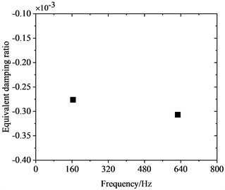
Fig. 3 depicts the frequency distribution of FIV in the WRS under high-speed train rolling-sliding condition. It is observed that the WRS has two unstable vibrations with negative EDRs, indicating the occurrence of FIV in the WRS. Instability is observed in these two vibrations at frequencies of 162.8 Hz and 622.7 Hz, respectively, with EDRs of –0.000275 and –0.000305 respectively. The mode shapes of these two vibrations with instability are depicted in Fig. 4. It can be observed that both unstable vibrations primarily manifest on the wheel. The 162.8 Hz unstable vibration is the yawing mode of the wheel, and the 622.7 Hz unstable vibration is the radial scaling mode of the wheel. The periodic yawing or radial scaling of the wheel can both lead to periodic oscillations of the friction power between wheel and rail, leading in periodic non-uniform wear of the wheel tread, resulting in the manifestation of PW. In accordance with the relationship between the order of PW and the unstable vibration frequency (, where denotes the PW order, stands for the frequency of unstable vibration, D represents the nominal wheel diameter, and signifies the speed), the 162.8 Hz unstable vibration will lead to 5th-6th order PW, and the 622.7 Hz unstable vibration will lead to 21st-22nd order PW. The two orders of PW both exist in reality on the wheels of high-speed trains in China [1], among which the 21st-22nd order PW is high-order PW with the most severe detriment, but its cause remains controversial. The complex eigenvalue analysis results indicate that the 21st-22nd order PW has a close correlation with the periodic radial scaling of the wheel induced by saturated creep force under driving condition.
Fig. 3Distribution of frequencies of the unstable vibrations
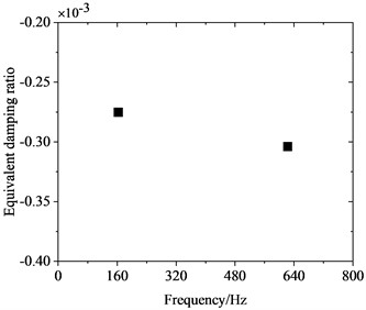
Fig. 4Vibration shapes of the unstable vibrations
a) 162.8 Hz
b)622.7 Hz
3.2. Time domain
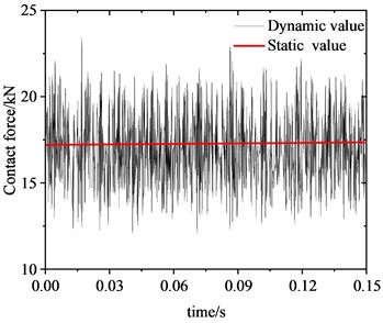
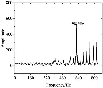
Fig. 5 illustrates the alteration in the contact force at the wheel-rail interface under rolling-sliding condition. Fig. 5(a) presents the time-domain representation of the wheel-rail contact force, and Fig. 5(b) shows the frequency distribution of the wheel-rail contact force, which was obtained employing fast Fourier transform (FFT) to the signal in the time domain. The transient dynamic response of the WRS, obtained through employing implicit time integration, is extremely computationally expensive. Therefore, only 0.15 s of the dynamic response process was simulated, which is adequate to capture the time-domain traits of FIV in the WRS. Meanwhile, since the simulation time is very short, the change of wheel velocity is negligible, so the wheel velocity can be assumed to be constant during this period. As shown in Fig. 5(a), under rolling-sliding condition, the dynamic contact force at the wheel-rail interface oscillates significantly between 55-95 kN, and the average peak dynamic contact force reaching approximately 95 kN, about 1.27 times of the static value of 75 kN. Since there is no external irregularity in the model, the oscillation of the contact force can be attributed to the FIV of the WRS. As shown in Fig. 5(b), there are several peak values in the vibration amplitude spectrum between 560-800 Hz, among which the peak at 608.7 Hz is the most significant, indicating this frequency is the dominant vibration frequency. This is near the 622.7 Hz estimated by the complex eigenvalue analysis. However, there are also some discrepancies between the complex eigenvalue analysis and the transient dynamic analysis. For example, no peak appears around 162.8 Hz in Fig. 5(b), indicating the unstable vibration at 162.8 Hz estimated by complex eigenvalue analysis is unlikely to occur.
Fig. 6 illustrates the variation in friction force at the wheel-rail interface. Under rolling-sliding conditions, substantial oscillations can be observed in the friction force at the wheel-rail interface as well, with an oscillation range spanning 12.5-22.5 kN. The average maximum value of the dynamic friction force is about 1.30 times of the static friction force of 17.25 kN. As shown in the frequency distribution of friction force in Fig. 6(b), a significant peak emerges at 598.9 Hz in the amplitude spectrum of the friction force vibration. This frequency is near 608.7 Hz, where a significant peak in the wheel-rail contact force is observed, and is also proximate to 622.7 Hz as estimated by the complex eigenvalue analysis. Fig. 7 shows the fluctuation of vibration acceleration on the wheel axle. To eliminate the impact of wheel rotational acceleration, the analysis of vibration acceleration is conducted at the center of wheel rotation. It is evident that the wheel axle acceleration fluctuates violently with an average amplitude of approximately 50 m/s2. Similarly, a significant peak also appears at 598.9 Hz in the wheel axle acceleration spectrum, which has a close frequency to peaks in the friction force and contact force spectrums.
The above analysis reveals that substantial vibrations arise in the contact force, friction force, and wheel axle acceleration during wheel rolling-sliding. These three vibrations have similar characteristics. The frequencies corresponding to the significant peaks in their vibration amplitude spectrums are consistent with the frequency of wheel radial scaling predicted by complex eigenvalue analysis. This indicates intense FIV occurs in the WRS under saturated creep force during rolling-sliding condition. The FIVs lead to fluctuations in the friction force and contact force at the wheel-rail interface, bringing about PW on wheels. The periodic radial scaling of the wheel induced by saturated creep force is a potential cause for the 21st-22nd order PW on Chinese high-speed train wheels.
Fig. 5Normal contact force at the wheel-rail interface
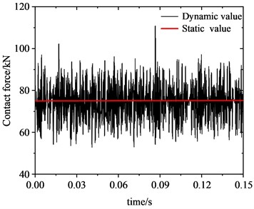
a) Time domain
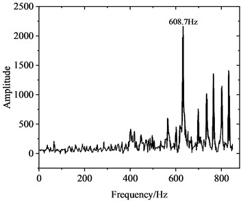
b) Frequency domain
Fig. 6Friction force at the wheel-rail interface
a) Time domain
b) Frequency domain
Fig. 7Acceleration at the wheel axle
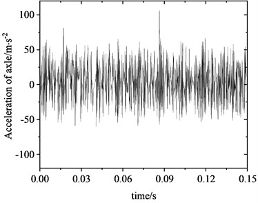
a) Time domain
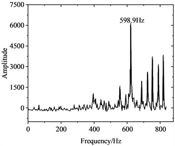
b) Frequency domain
4. Effect of vehicle speed on PW
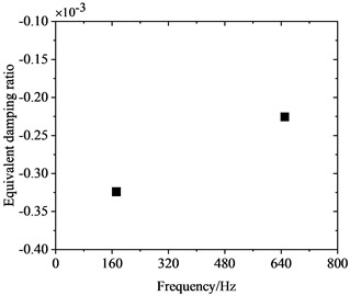
To investigate the correlation between PW on high-speed train wheels and vehicle speed, the frequency-domain trains of FIV in the WRS under rolling-sliding condition were comparatively analyzed at several common operating speeds of Chinese high-speed trains, including 200 km/h, 250 km/h, 300 km/h and 350 km/h. Fig. 8 shows the influence of vehicle speed on FIV in the WRS. Under the four operating speeds examined, two unstable vibrations with negative EDRs are observed to arise in the WRS during rolling-sliding at the wheel-rail interface. This indicates that FIV occur in the WRS under all the four operating speeds. The frequencies of the instable vibrations are around 160 Hz and 640 Hz respectively. The impact of vehicle speed on the frequency distribution of FIV in the WRS is small, indicating the frequencies of FIV not significantly influenced by changes in vehicle speed. Nonetheless, the EDR, which determines the likelihood and growth rate of unstable vibrations, changes notably with vehicle speed. Fig. 9 more clearly depicts the variation of frequency and EDR of unstable vibrations in the WRS with vehicle speed. As analyzed in the previous section, the unstable vibration around 160 Hz (yawing mode) is not closely related to PW on wheels. Therefore, Fig. 9 only shows the variation of the unstable vibration around 640 Hz (radial scaling mode) with vehicle speed. As depicted in Fig. 9(a), under the four operating speeds, the frequency of the radial scaling mode of the wheel varies slightly from 607 Hz to 623 Hz. Vibrations that are unstable within this frequency range will lead to 31st-32nd, 25th-26th, 21st-22nd, and 18th-19th order PW at the respective operating speeds of 200 km/h, 250 km/h, 300 km/h, and 350 km/h. As shown in Fig. 9(b), the absolute value of the EDR associated with the radial scaling mode increases as vehicle speed rises. As the speed elevates from 200 km/h to 350 km/h, its EDR rises from 0.000227 to 0.000368, with an increase of 62.1 %. This considerable increase indicates that the higher the speed, the more likely the FIV occurs in the WRS, the faster it develops, and the more severe PW it leads to.
Fig. 8Influence of the vehicle speed on the FIV of the WRS
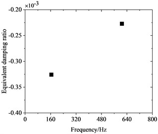
a) 200 km/h
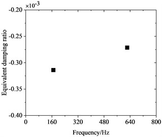
b) 250 km/h
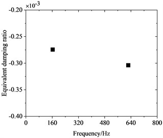
c) 300 km/h
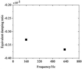
d) 350 km/h
Fig. 9Variation of the FIV of the WRS with vehicle speed
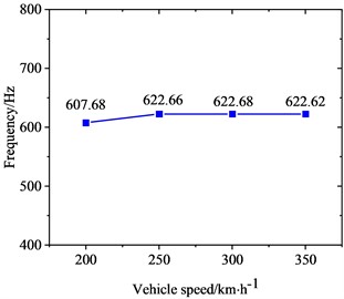
a) Frequency
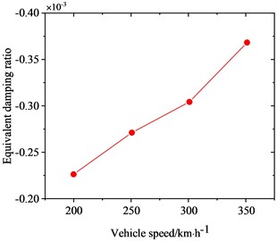
b) Equivalent damping ratio
5. Effect of wheel diameter on PW
Wheel diameter decreases continuously during service due to wear and reprofiling. To investigate the influence of wheel diameter on PW, frequency-domain traits of FIV in the WRS were comparatively analyzed for three different wheel diameters, all at an operating speed of 300 km/h. Fig. 10 shows the influence of wheel diameter on FIV in the WRS. It is evident that when the three different wheel diameters undergo rolling and sliding at 300 km/h, FIV materialize in the WRS. The system exhibits two instable vibrations with frequencies around 160 Hz and 640 Hz. Among them, the frequency of the instable vibration at around 160 Hz shows minimal variation with changes in wheel diameter, while the frequency of the instable vibration around 640 Hz shows an increasing trend as the wheel diameter decreases. Also, its absolute value of EDR decreases notably as the wheel diameter reduces.
Fig. 10Influence of the wheel diameter on the FIV of the WRS
a) 895 mm
b) 910 mm
c) 920 mm
Fig. 11Variation of the FIV of the WRS with wheel diameter
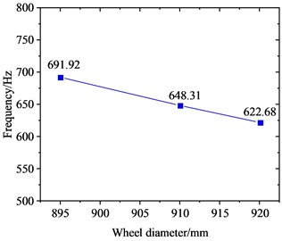
a) Frequency
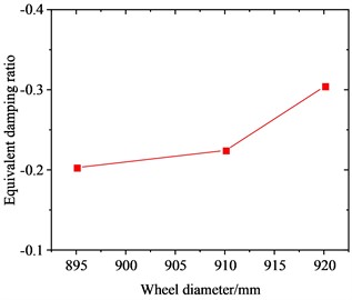
b) Equivalent damping ratio
Fig. 11 clearly shows the variation of the radial scaling mode of the wheel around 640 Hz with wheel diameter. Fig. 11(a) shows that as the wheel diameter increases, the frequency of the radial scaling mode decreases continuously. As the diameter increases from 895 mm to 920 mm, the frequency of this vibration mode decreases from 691.92 Hz to 622.68 Hz, with a reduction of about 10.0 %. This change is relatively small. When the 895 mm, 910 mm and 920 mm diameter wheels roll and slide at 300 km/h, they will lead to 23rd-24th, 22nd-23rd and 21st-22nd order PW, respectively. Fig. 11(b) shows that as the wheel diameter is increased, the absolute value of the EDR corresponding to the radial scaling mode exhibits a continuous increase. As the diameter advances from 895 mm to 920 mm, its EDR rises from 0.000203 to 0.000305, with an increase of about 50.2 %. This indicates that the larger the wheel diameter, the more likely FIV occurs in the WRS, and the more severe PW it leads to.
6. Conclusions
The conclusions obtained in this study are as follows:
1) Under rolling-sliding condition, the saturated creep force at the wheel-rail interface causes FIV in the WRS. The vibration causes fluctuations in wheel-rail friction power and contact force, eventually leads to PW on high-speed train wheels. The wheel radial scaling mode at the frequency of about 622 Hz excited by the saturated creep force, constitutes a potential cause underlying the 21st-22nd order PW on Chinese high-speed train wheels.
2) Vehicle speed has little influence on the frequency distribution of FIV in the WRS. Relative to vehicle speed, the frequency of the wheel radial scaling mode that causes high-order PW displays some constant traits, namely that the order of PW has a linear correlation with vehicle speed. The four operating speeds of 200 km/h, 250 km/h, 300 km/h and 350 km/h will lead to 31st-32nd, 25th-26th, 21st-22nd and 18th-19th order PW, respectively. As vehicle speed increases, it is more likely for FIV to occur in the WRS, the faster it develops, and the more severe PW becomes.
3) Wheel diameter exhibits some effect on the frequency distribution of FIV in the WRS. As wheel diameter increases, the frequency of wheel radial scaling mode decreases. When the 895 mm, 910 mm and 920 mm diameter wheels roll and slide at 300 km/h, they will lead to 23rd-24th, 22nd-23rd and 21st-22nd order PW, respectively. The larger the wheel diameter, the more likely FIV occurs in the WRS, and the more severe PW it leads to.
References
-
X. Jin, Y. Wu, S. Liang, and Z. Wen, “Mechanisms and countermeasures of out-of-roundness wear on railway vehicle wheels,” (in Chinese), Journal of Southwest Jiaotong University, Vol. 53, No. 1, pp. 1–14, Jan. 2018, https://doi.org/10.3969/j.issn.0258-2724.2018.01.001
-
G. Tao, Z. Wen, and X. Jin, “Advances in formation mechanism and mitigation measures of out-of-round railway vehicle wheels,” (in Chinese), Journal of Mechanical Engineering, Vol. 57, No. 6, p. 106, 2021, https://doi.org/10.3901/jme.2021.06.106
-
J. Liu, “Influence of wheel non-circular wear on axle box cover abnormal vibration in high-speed train,” (in Chinese), Journal of Mechanical Engineering, Vol. 53, No. 20, p. 98, 2017, https://doi.org/10.3901/jme.2017.20.098
-
J. Zhang and X.-S. Jin, “Influence of wheel polygonal wear on interior noise of high-speed trains,” Journal of Zhejiang University Science A, Vol. 15, No. 12, pp. 1002–1018, Dec. 2014, https://doi.org/10.1631/jzus.a1400233
-
D. Cui et al., “Effect of the turning characteristics of underfloor wheel lathes on the evolution of wheel polygonisation,” Proceedings of the Institution of Mechanical Engineers, Part F: Journal of Rail and Rapid Transit, Vol. 233, No. 5, pp. 479–488, May 2019, https://doi.org/10.1177/0954409718795760
-
M. Meywerk, “Polygonalization of railway wheels,” Archive of Applied Mechanics (Ingenieur Archiv), Vol. 69, No. 2, pp. 105–120, Mar. 1999, https://doi.org/10.1007/s004190050208
-
B. Morys, “Enlargement of out-of-round wheel profiles on high speed trains,” Journal of Sound and Vibration, Vol. 227, No. 5, pp. 965–978, Nov. 1999, https://doi.org/10.1006/jsvi.1999.2055
-
W. Rode, D. Muller, and J. Villman, “Results of DB AG investigation-out-of-round wheels,” in Proceedings of Corrugation Symposium – Extended Abstracts, 1997.
-
J. C. O. Nielsen, R. N. Lunden, A. Johansson, and T. Vernersson, “Train-track interaction and mechanisms of irregular wear on wheel and rail surfaces,” Vehicle System Dynamics, Vol. 40, No. 1-3, pp. 3–54, Jan. 2003, https://doi.org/10.1076/vesd.40.1.3.15874
-
R. Fröhling, U. Spangenberg, and E. Reitmann, “Root cause analysis of locomotive wheel tread polygonisation,” Wear, Vol. 432-433, p. 102911, Aug. 2019, https://doi.org/10.1016/j.wear.2019.05.026
-
U. Spangenberg, “Variable frequency drive harmonics and interharmonics exciting axle torsional vibration resulting in railway wheel polygonisation,” Vehicle System Dynamics, Vol. 58, No. 3, pp. 404–424, Mar. 2020, https://doi.org/10.1080/00423114.2019.1581235
-
B. Peng, S. Iwnicki, P. Shackleton, D. Crosbee, and Y. Zhao, “The influence of wheelset flexibility on polygonal wear of locomotive wheels,” Wear, Vol. 432-433, p. 102917, Aug. 2019, https://doi.org/10.1016/j.wear.2019.05.032
-
X. Jin, L. Wu, J. Fang, S. Zhong, and L. Ling, “An investigation into the mechanism of the polygonal wear of metro train wheels and its effect on the dynamic behaviour of a wheel/rail system,” Vehicle System Dynamics, Vol. 50, No. 12, pp. 1817–1834, Dec. 2012, https://doi.org/10.1080/00423114.2012.695022
-
G. Tao, L. Wang, Z. Wen, Q. Guan, and X. Jin, “Experimental investigation into the mechanism of the polygonal wear of electric locomotive wheels,” Vehicle System Dynamics, Vol. 56, No. 6, pp. 883–899, Jun. 2018, https://doi.org/10.1080/00423114.2017.1399210
-
G. Tao, Z. Wen, X. Liang, D. Ren, and X. Jin, “An investigation into the mechanism of the out-of-round wheels of metro train and its mitigation measures,” Vehicle System Dynamics, Vol. 57, No. 1, pp. 1–16, Jan. 2019, https://doi.org/10.1080/00423114.2018.1445269
-
G. Tao, C. Xie, H. Wang, X. Yang, C. Ding, and Z. Wen, “An investigation into the mechanism of high-order polygonal wear of metro train wheels and its mitigation measures,” Vehicle System Dynamics, Vol. 59, No. 10, pp. 1557–1572, Oct. 2021, https://doi.org/10.1080/00423114.2020.1770810
-
G. Chen, X. Jin, P. Wu, H. Dai, and Z. Zhou, “Finite element study on the generation mechanism of polygonal wear of railway wheels,” (in Chinese), Journal of the China railway society, Vol. 33, No. 1, pp. 14–18, Jan. 2011, https://doi.org/10.3969/j.issn.1001-8360.2011.01.003
-
Q. Qiao, M. Li, X. Zhao, and G. Chen, “Mechanism of suppression of polygonal wear of wheel on high-speed trains by abrasive block,” (in Chinese), Tribology, Vol. 40, No. 2, pp. 234–239, Apr. 2020, https://doi.org/10.16078/j.tribology.2019037
-
X. Zhao, G. Chen, X. Cui, J. Lyu, S. Zhang, and Q. Zhu, “Formation mechanism and influencing factors of the polygonal wear of high-speed train wheels,” (in Chinese), Surface Technology, Vol. 47, No. 8, pp. 8–13, Aug. 2018, https://doi.org/10.16490/j.cnki.issn.1001-3660.2018.08.002
-
X. Zhao, G. Chen, X. Kang, Q. Zhu, S. Zhang, and J. Lv, “Mechanism of polygonal wear on wheels of electric multiple units on Lanzhou-Xinjiang passenger dedicated line,” (in Chinese), Journal of Southwest Jiaotong University, Vol. 55, No. 2, pp. 364–371, Apr. 2020, https://doi.org/10.3969/j.issn.0258-2724.20190027
-
B. Wu et al., “Effect of the unstable vibration of the disc brake system of high-speed trains on wheel polygonalization,” Proceedings of the Institution of Mechanical Engineers, Part F: Journal of Rail and Rapid Transit, Vol. 234, No. 1, pp. 80–95, Jan. 2020, https://doi.org/10.1177/0954409719833787
-
B. Wu, T. Liu, X. Wang, J. Pan, and R. Zhang, “Cause analysis of polygonalization of the high-speed train wheels based on the finite element method,” (in Chinese), Tribology, Vol. 42, No. 1, pp. 131–141, Mar. 2021, https://doi.org/10.16078/j.tribology.2020250
-
Y. Wu, X. Du, H.-J. Zhang, Z.-F. Wen, and X.-S. Jin, “Experimental analysis of the mechanism of high-order polygonal wear of wheels of a high-speed train,” Journal of Zhejiang University-Science A, Vol. 18, No. 8, pp. 579–592, Aug. 2017, https://doi.org/10.1631/jzus.a1600741
-
Y. Wu, “Effect of high-speed train polygonal wheels on wheel/rail contact force and bogie vibration,” (in Chinese), Journal of Mechanical Engineering, Vol. 54, No. 4, p. 37, 2018, https://doi.org/10.3901/jme.2018.04.037
-
C. Ma, L. Gao, R. Cui, and T. Xin, “The initiation mechanism and distribution rule of wheel high-order polygonal wear on high-speed railway,” Engineering Failure Analysis, Vol. 119, p. 104937, Jan. 2021, https://doi.org/10.1016/j.engfailanal.2020.104937
-
G. Tao, Z. Wen, G. Chen, Y. Luo, and X. Jin, “Locomotive wheel polygonisation due to discrete irregularities: simulation and mechanism,” Vehicle System Dynamics, Vol. 59, No. 6, pp. 872–889, Jun. 2021, https://doi.org/10.1080/00423114.2020.1737148
-
G. X. Chen, Z. R. Zhou, H. Ouyang, X. S. Jin, M. H. Zhu, and Q. Y. Liu, “A finite element study on rail corrugation based on saturated creep force-induced self-excited vibration of a wheelset-track system,” Journal of Sound and Vibration, Vol. 329, No. 22, pp. 4643–4655, Oct. 2010, https://doi.org/10.1016/j.jsv.2010.05.011
-
X. Zhao, “3D transient finite element model for high-speed wheel-rail rolling contact and its application,” (in Chinese), Journal of Mechanical Engineering, Vol. 49, No. 18, pp. 1–7, 2013, https://doi.org/10.3901/jme.2013.18.001
-
G. Chen, X. Cui, Liu, and K. Wang, “Generation mechanism for plolygonalization of wheel treads of high-speed trains,” Journal of Southwest Jiaotong University, Vol. 51, No. 2, pp. 244–250, Apr. 2016, https://doi.org/10.3969/j.issn.0258-2724.2016.02.004
-
C. A. Brockley and P. L. Ko, “An investigation of rail corrugation using friction-induced vibration theory,” Wear, Vol. 128, No. 1, pp. 99–106, Nov. 1988, https://doi.org/10.1016/0043-1648(88)90256-6
About this article

The authors would like to acknowledge the financial support of the Anhui Higher Education for Outstanding Youth Science Foundation (Grant No. 2022AH030099), Natural Science Foundation of the Anhui Higher Education (Grant No. KJ2020A0360), Anhui Provincial Natural Science Foundation (Grant No. 2108085ME169) and National Key Laboratory of Science and Technology on Helicopter Transmission (Grant No. HTL-O-22G01).
The datasets generated during and/or analyzed during the current study are available from the corresponding author on reasonable request.
Zengchuang Zhao, Bowen Wu, Wenjing Wang, and Jiabao Pan oversaw validation, writing (review and editing), funding acquisition, visualization and resources. Tiancheng Tang oversaw the methodology, software, formal analysis, data curation, and writing (original draft preparation).
The authors declare that they have no conflict of interest.
