Abstract
Short-pitch corrugation is a common phenomenon that occurs on tight-curve rails in metro systems. However, the contributing factors of this problem are still not fully understood, and effective control measures have yet to be developed. In this study, we investigated the contributing factors of short-pitch corrugation on tight-curve rails in metro systems using the complex eigenvalue analysis method according to the theory of friction-induced vibration. We also explored control measures for short-pitch corrugation from the perspective of optimizing the wheel web structure. Our results indicate that friction-induced vibration is the primary contributing factor to short-pitch corrugation in the wheel-rail system. The shape of the web structure significantly affects rail corrugation, and compared to the straight web structure, unstable vibrations are more pronounced in the S-shape web structure. In contrast, the bow web structure can significantly improve the system stability of the wheel-rail interaction, and the greater the web curvature, the better the inhibitory effect. The wheel deformation under contact force varies with the web curvature, and when the axial deformation of the wheel extends toward the inner rail, the wheel-rail system no longer exhibits unstable vibrations. Conversely, when the axial deformation of the wheel extends toward the outer rail, the greater the deformation, the greater the instability of the wheel-rail system.
Highlights
- The shape of the web structure significantly affects the short-pitch corrugation.
- The straight-web wheel can alleviate but can’t eliminate the short-pitch corrugation.
- The bow web structure can significantly improve the system stability of the wheel-rail interaction.
- The wheel deformation varies with web curvature, and when it extends towards the inner rail, unstable vibrations are eliminated in the wheel-rail system.
1. Introduction
Rail corrugation is a form of periodic uneven wear that occurs longitudinally along the surface of the rail [1]. In China's metro system, rail corrugation is widespread, particularly in tight-curve rails. Statistics indicate that about 80 % of rail corrugations occur in tight-curve rails [2], with the majority being short-pitch corrugations, which have wavelengths ranging from 20 mm to 80 mm and wave depths ranging from 0.1 mm to 0.5 mm [3]. Rail corrugation can cause a significant dynamic interaction between the wheel-rail system, hereinafter referred to as WRS, causing vibrations in the vehicle-rail system and noise emission from the wheel-rail interface [4, 5]. In serious cases, it will also lead to the fracture of the fastener clips [6]. However, the contributing factors of short-pitch corrugation remain unclear, and effective control measures have yet to be developed.
At present, the generally accepted mechanisms for rail corrugation are material damage mechanism and the wavelength-fixing mechanism [7, 8]. The former emphasizes the response dynamics of the wheel-rail coupling, while the latter is mainly characterized by wear and plastic deformation of the rail. Zhu et al. [9] classified the contributing factors of rail corrugation into two categories: dynamic and nondynamic. In accordance with the dynamic theory, rail corrugation is a result of the vibration in the WRS, with vibration types categorized as self-excitation, resonance, and feedback. The contributing factors of wave corrugation are classified into the following theories: self-excited vibration theory, feedback vibration theory, and other theories [10]. Stemming from the inherent characteristics of the WRS, self-excited vibration arises in accordance with the theory of self-excited vibration, resulting in rail corrugation [11-14]. Feedback vibration theory states that wave corrugation develops from initial irregularities [15, 16]. Nondynamic theory suggests that uneven plastic flow, resulting from material inhomogeneity, leads to rail corrugation [17]. Nevertheless, a unanimous understanding regarding the formation mechanism of rail corrugation is yet to be reached, requiring further investigation.
Based on theoretical research results, various rail corrugation control measures have been developed, such as vibration absorbers [18-20], friction adjusters [21, 22], and control of vehicle speed [23], which have shown good results but cannot completely eliminate rail corrugation. Chen et al. [24] studied the effect of sleeper pad rigidity on rail corrugation, and found that higher rigidity of sleeper pads can accelerate corrugation development, while reducing the rigidity of sleeper pads can effectively alleviate rail corrugation. Wu et al. [25] investigated rail corrugation in the pioneer fastener section of tight curves and discovered that the damping and elastic modulus of the rubber bearing block make a crucial impact on rail corrugation, and increasing them can help restrain rail corrugation. Gonzelez et al. [26] proposed controlling the relative angle and shaking moment of the wheelset by using an active steering system to manage the creep rate and creep force at the wheel-rail interface, thereby controlling rail corrugation. Hiensch et al. [27] drew conclusions based on field tests and numerical simulations of rail corrugation on the railway that replacing harder fasteners with softer ones can reduce the vertical force at the wheel-rail interface, which helps alleviate the formation of rail corrugation. While the existing research has played a critical role in reducing rail corrugation, finding a solution to this problem’s root cause is essential, particularly in light of increasing rail traffic volume, axle load, and train speed.
This study examines the causes of short-pitch corrugation on the tight curves in metro systems utilizing the theory of the friction-induced vibration, hereinafter referred to as FIV. Finite element models of wheels with various web structures were constructed, and the complex eigenvalue analysis method was employed to investigate the impact of the wheel web structure on the stability of the WRS. Our findings reveal that increasing the curvature of a wheel web can effectively suppress the growth and evolution of rail corrugation, and proper control of the web curvature can prevent or even eliminate short-pitch corrugation on tight curves.
2. Theory and model
2.1. Construction of the finite element model
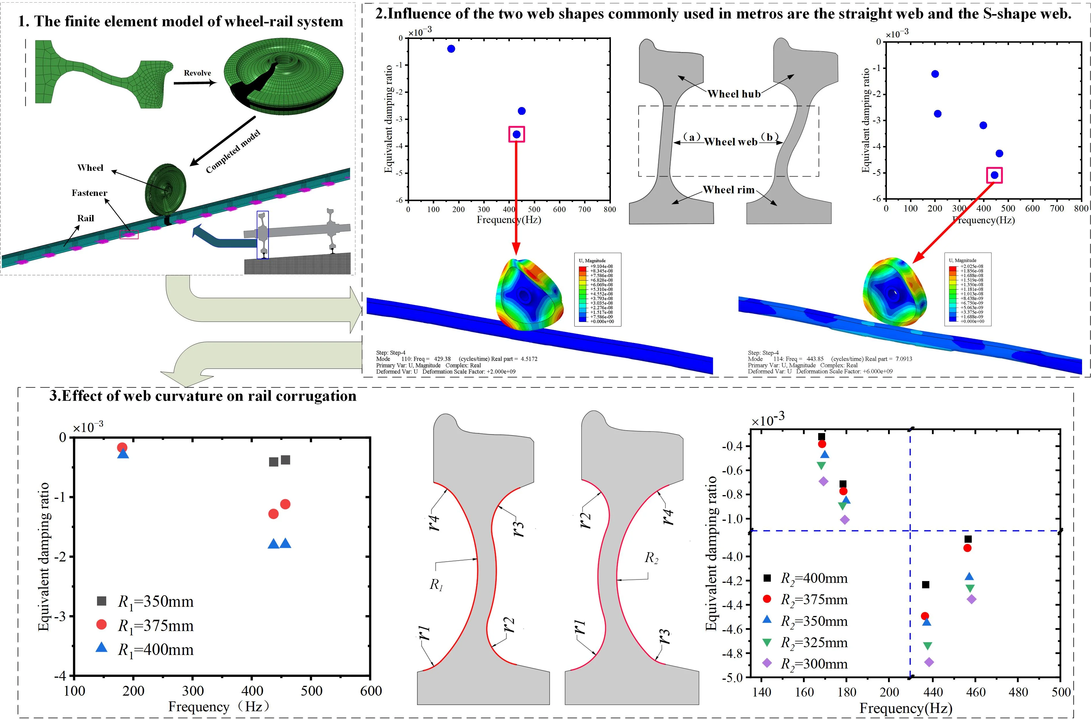
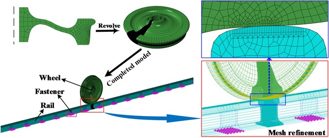
Rail corrugation typically observed on the lower rail of tight-curve rails. Therefore, we constructed a finite element model for the lower rail in the WRS is depicted in Fig. 1. The model consists of wheels, rails, and fasteners, with specific parameters detailed in Table 1.
To simulate the action of the e-type clip fastener system, we employed grounding springs and damping elements, with specific parameters listed in Table 2. Dynamic analysis software was employed to derive the angle of attack, angle of contact and lateral displacement of the finite element model of the WRS. A friction coefficient of 0.3 was set at the wheel-rail interface, with a “face-to-face” contact algorithm, implemented using the penalty function utilized to describe the contact interaction between the rail and wheel. The tangential contact behavior between the rail and wheel was modeled using the Coulomb friction method.
For the boundary conditions of the WRS, we constrained the lateral motion of the wheel axle end. Additionally, we released the vertical degree of freedom of the reference point and coupling all nodes on the axle surface with this reference point. A spring mass was used with a vertical concentrated force of 45.5 kN on the reference point, whose numerical value was obtained using the dynamic analysis software. We discretized the wheel and rail using the 3D 8-node incompatible element. To improve the calculation speed of the wheel-rail finite element model without compromising accuracy, the model was divided into uneven grids. In the region where the wheel and rail contact, the grid was refined to 1 × 1 mm, is used on the contact surfaces to solve the wheel–rail rolling contact accurately [28]. The resulting model includes 230,740 nodes and 195,725 solid elements.
Table 1Structural parameters of the 3D solid finite element model for the WRS
Component | Parameter | Value |
Rail | Track length / m | 36 |
Rail cant | 1:40 | |
Sleeper span / mm | 640 | |
Density / (kg·m-3) | 7800 | |
Elastic modulus / GPa | 210 | |
Poisson ratio | 0.3 | |
Wheel | tread profile | LM |
diameter / mm | 840 | |
Density / (kg·m-3) | 7800 | |
Elastic modulus / GPa | 210 | |
Poisson ratio | 0.3 |
Table 2Fastener parameters
Fastener parameters | Longitudinal | Vertical | Lateral |
Stiffness (MN/m) | 10 | 30 | 10 |
Damping (N·s/m) | 2 | 10 | 2 |
Fig. 1Contact model of the wheel under steady-state rolling
2.2. Steady-state rolling analysis theory of WRS
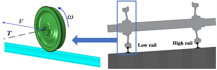
As shown in Fig. 2, the wheel under steady-state rolling rotates around the rotating axis at a fixed angular speed and translates at a fixed forward speed . When describing the steady-state rolling of the wheelset, the mixed Lagrangian/Eulerian method is employed, wherein the rigid rotation of the wheel around the axle is described using the Euler method, and the deformation of the wheel is described by the Lagrangian method. When the particles of the wheel move from location to location , the new spatial coordinates of the particles can be represented as:
where is the rotation matrix:
We suppose that the deformation is dependent on the rigid body rotation , namely, .
Subsequently, the particle velocity can be expressed as:
Where . Suppose that , where represents the nominal rolling radius at the particle's location, leading to the simplification of Eq. (3) as follows:
Under steady-state rolling, ; then, , and the overall velocity of this particle is:
In this paper, the steady-state motion analysis function in Abaqus/Standard is utilized to simulate the steady-state rolling process of the wheel on the rail through finite element analysis. With this algorithm, the steady-state motion contact is converted into a pure simulation in space.
Fig. 2Steady-state rolling model of the wheel
2.3. Complex eigenvalue analysis method
The method of complex eigenvalue analysis is linear [29, 30]. When self-excited vibrations occur due to friction, this method can be employed in the frequency domain to predict the system’s vibration mode and frequency, and to evaluate its stability. In this paper, the complex eigenvalue analysis algorithm built in ABAQUS software is employed to explore the motion trend of the FIV of the WRS in the frequency domain. Based on the method proposed by Chen et al. [31], the dynamic equation of wheel-rail friction contact coupling is established; when the system involves no friction, the overall motion equation of the WRS is:
The matrices , , and represent the mass, damping, and stiffness properties, respectively, and represents the node displacement column vector.
Without taking friction into account, , and represent the symmetric matrices, that is, in Eq. (6), it is observed that the real part of the eigenvalue is not positive; when friction is introduced, the dynamic equation of the system can be simplified as:
where, the mass, damping, and stiffness matrices of the simplified system are defined as , and ; the above matrices are all asymmetric; the stability of the studied system is determined by the solution of the matrix equation; and the characteristic equation of the equation is:
where represents the eigenvalue of the system, and represents the eigenvector of the system. By solving the characteristic equation, its general solution is:
where represents the eigenvector of the characteristic equation; represents the eigenvalue of the characteristic equation; represents the real part of the eigenvalue; represents the imaginary part of the eigenvalue; and j represents the imaginary part unit. When the system presents a trend of FIV, and with the increase in , the tendency of FIV of the system becomes stronger. The motion stability of the system can be determined by utilizing the equivalent damping ratio, hereinafter referred to as EDR, which is described as:
where signifies the real part of complex eigenvalue , while signifies the imaginary part. When 0, it indicates that the system tends to be unstable. The smaller is, the more obvious the trend of FIV.
Analyzing the friction-induced vibration of the wheel-rail system using complex eigenvalue analysis involves four procedures: solving the wheel-rail contact solution, steady-state rolling, extracting the natural frequencies, and determining the complex eigenvalues.
3. Influence of different wheel web structures on the FIV of the WRS
3.1. Influence of the wheel web shape on unstable vibration of the WRS
The wheels of a metro consist of a hub, a rim, and a web connecting them. The primary difference lies in the shape of the web. The two web shapes commonly used in metros are the straight web and the S-shape web. Fig. 3 depicts the two-dimensional cross-sections of the two web shapes, with (a) representing the straight web, and (b) representing the S-shape web. In this section, we investigate whether the web structure influences the unstable vibration of the WRS.
Fig. 4 displays the frequency distribution diagram of the unstable vibration of the WRS, highlighting the influence of different web structures. The diagram signifies that the unstable vibration frequency occurs in the WRS with both web structures, with unstable vibration frequencies possessing an EDR below -0.001. When the EDR is below –0.001, the system damping is difficult to overcome, leading to rail corrugation, which aligns with the occurrence of rail corrugation to some extent on the tight-curve rail of the metro. The key difference is that the negative EDR of the dominant unstable vibration frequency in the WRS is smaller for wheels with the S-shape web structure. This finding suggests that the WRS with the S-shape web structure is more susceptible to unstable vibration.
Fig. 3Cross sections of wheels with two web shapes: a) straight web and b) S-shape web
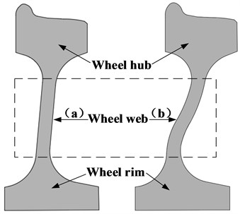
Fig. 4Frequency distribution of unstable vibration of WRS with different web structures
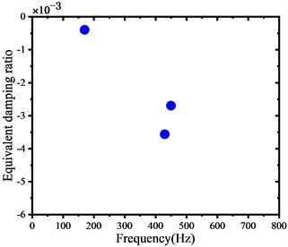
a) Straight web
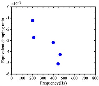
b) S-shape web
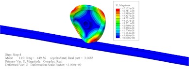
Fig. 5 and 6 exhibit the modal shapes associated with the unsteady vibrations observed in the WRS, which suggest that the unstable vibration primarily occurs in the wheels. The WRS with the S-shape web structure exhibits unstable modes, including axial modes at 443.85 Hz and 463.79 Hz, umbrella mode at 397.86 Hz, rolling vibration at 210.97 Hz, and yaw vibration at 200.53 Hz, respectively. Additionally, another unstable mode of the WRS is the axial modes of 449.56 Hz and 429.38 Hz. The primary frequency range for unstable vibration in both WRSs falls within the 430-470 Hz range, which closely to the passing frequency of rail corrugation on tight-curve rails in the actual metro systems.
Fig. 5Modal shape of unstable vibration of WRS with S-shape web
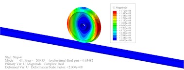
a) Unstable vibration mode shape with a frequency of 200.53 Hz
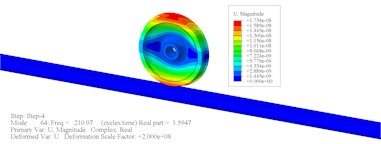
b) Unstable vibration mode shape with a frequency of 210.97 Hz
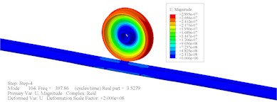
c) Unstable vibration mode shape with a frequency of 397.86 Hz
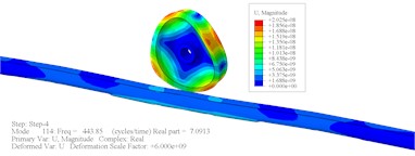
d) Unstable vibration mode shape with a frequency of 443.85 Hz
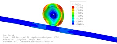
e) Unstable vibration mode shape with a frequency of 463.79 Hz
Fig. 6Modal shape of unstable vibration of WRS of straight web
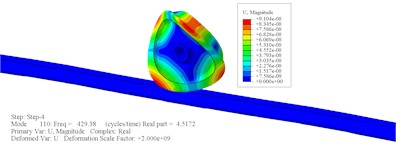
a) Unstable vibration mode shape with a frequency of 429.38 Hz
b) Unstable vibration mode shape with a frequency of 449.56 Hz
In conclusion, the web structure of the wheelset has a notable influence on the stability of the WRS. The development of rail corrugation in the WRS with the S-shape web structure is more likely to occur and progress compared to that with the straight web structure, where the development of rail corrugation is relatively slower.
3.2. Effect of web curvature on rail corrugation
In this section, we examine the impact of web curvature on the unstable vibration of the WRS and a wheel with bow web structure is designed. Fig. 7 depicts the schematic diagram of the wheel with a bow web structure, which stems from the optimal design of the wheel with a straight web structure in the upper section. To ensure reliable outcomes, the relative position of the rim and hub remain unchanged, while the modeling parameters such as wheel tread, rolling radius, and wheel axle radius remain consistent. Fig. 7(a) showcases the bow web structure, which comprises four short transition arcs with radii of , , , and , and a long arc with a radius of that determines the shape of the wheel web; the web thickness is 25 mm. Based on this web structure, we design a wheel with a bow web structure at a different radius . The radius of the bow web ranges from 275 mm to 400 mm, with a span of 25 mm, resulting in six wheels with varying web structures.
Fig. 7Bow web curvature diagram
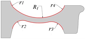
a) Bow web
b) Reverse bow web
Fig. 8 exhibits the transformation of the EDR of the WRS concerning the web curvature, indicating that the negative EDR appears and gradually decreases as the web curvature decreases. The negative EDR is absent in the analysis results of the wheel with a web radius ranging from 275 mm to 325 mm; thus, it is not shown in the figure, signifying that the WRS within the web radius range is not impacted by FIV. Upon comparing the analysis outcomes in the previous section, it is evident that the stability of the WRS of the bow web structure surpasses that of the straight web and S-shape web, fully exhibiting the advantages of its structure.
Fig. 8Effect of bow web curvature on unstable vibration of the WRS
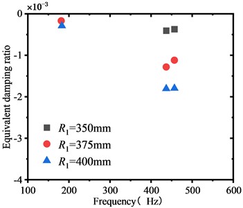
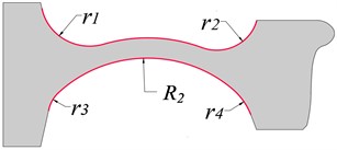
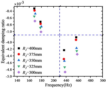
Fig. 7(b) illustrates the wheel with the reverse bow web structure, which has a structure similar to that of the wheel with the bow web structure, except for the direction of the long arc in the middle, which is opposite. Based on this web structure, we design a wheel with a reverse bow web structure at a different radius ; the web radius ranges from 300 mm to 400 mm, with a span of 25 mm. Fig. 9 displays the distribution of the EDR of the reverse bow web structure concerning the web curvature. Compared to the analysis results of the straight web structure and the bow web structure, the negative EDR of the reverse bow web structure significantly declines, indicating that the WRS of the reverse bow web structure is more unstable. As the web curvature increases, the EDR decreases, leading to an increased likelihood of rail corrugation.
Fig. 9Effect of curvature of reverse bow web on unstable vibration of the WRS
The research results indicate that the curvature of the wheel web significantly affects the unstable vibration of the WRS. Compared to wheels with the conventional straight web structure and the S-shape web structure, wheels with the bow web structure effectively mitigates rail corrugation caused due to FIV. The greater the web curvature, the more effective the control, suggesting that using a bow web structure instead of a conventional web structure offers significant advantages in improving the stability of the WRS. Conversely, the reverse bow web structure aggravates the unstable vibration of the WRS and accelerates the growth of rail corrugation.
4. Discussion
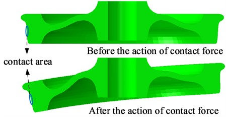
This study focuses on analyzing how the wheel web structure influences the formation of short-pitch corrugation on tight curves. The web shape significantly affects the occurrence of unstable vibrations in the WRS, whether it is a straight web, an S-shape web or a bow web. The finite analysis results of WRS with different web structures show that the wheels experience slight elastic deformation after contacting the rail under the action of gravity, and the deformation of wheels with different web structures is significantly different. Fig. 10 compares the deformation of the S-shape web before and after being subject to the contact force, and the deformation scale factor is 1,000, indicating that the deformation of wheels is mainly reflected in the axial change.
Fig. 10Comparison before and after wheel deformation
To fully reflect the degree of axial deformation of webs with different structures, the axial displacement (Define a positive direction towards the inner rail) is recorded at the position shown in Fig. 11 as the standard to measure the degree of wheel deformation. Fig. 12 shows the change in the axial displacement of wheels with different web structures with the contact force, indicating significant differences in the axial deformation of wheels with different web structures. The axial deformation extends toward the inner rail or the outer rail, and according to the research results of this paper, when the axial deformation extends toward the inner rail, there is no unstable vibration mode of the WRS; when it extends toward the outer rail, the smaller the slope, the easier it is to cause FIV.
Fig. 11Schematic diagram of the axial deformation value of the wheel
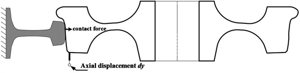
Fig. 12Axial deformation of wheel
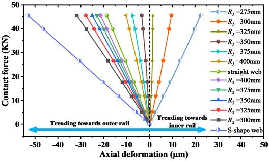
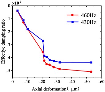
Fig. 13 depicts the relationship between the EDR of the two primary unstable vibration modes with a frequency of approximately 450 Hz and the axial displacement when the wheel and the rail are in stable contact. When the axial deformation of the wheel points to the outer rail, the greater the value of the axial displacement when the rail is in stable contact, the greater the absolute value of the EDR of the primary unstable vibration mode, and the more unstable the WRS where equation is inside the table with no borders.
Fig. 13Change in the EDRs of two primary unstable vibration frequencies with the axial deformation dy when the wheel and the rail are in stable contact
To explore whether “the unstable vibration mode of the WRS disappears when the axial deformation of the wheel points to the inner rail” can be established under any working conditions of the WRS, the research results of Cui et al. [32, 3] indicate that the rigidity of the rail fastener and the coefficient of friction at the wheel-rail contact interface is critical for the unstable vibration of the WRS. Accordingly, the e-type clip fastener in the original model is replaced with the Cologne egg fastener, trapezoidal sleeper fastener, DTV12 fastener, Vanguard fastener, and floating rail damping fastener, and the value of the friction coefficient of 0.3 in the original WRS is changed to 0.2, 0.4, and 0.5 for recalculation of the wheel whose axial deformation points to the inner rail. The results show no unstable modes in the WRS after the change in the fastener system or the wheel-rail contact friction coefficient, indicating the applicability of the research results in this paper.
The axial deformation of the wheel is the primary determinant of vehicle operational stability. This conclusion inspires wheel design; that is, if the axial deformation of the wheel in contact with the rail is considered in the early stage of wheel development, it will significantly alleviate or even eradicate the short-pitch corrugation on the tight curve of the metro.
5. Conclusions
The present study investigates the impact of wheel web structure on the stability of the WRS in metro railways. Utilizing finite element analysis software and complex eigenvalue analysis, the study explores the control measures for short-pitch corrugation on tight curves by optimizing the wheel web parameters. The following conclusions are drawn:
(1) Different wheel web structures significantly affect the stability of the WRS. The S-shape web structure exhibits a higher inclination to FIV than the straight web structure.
(2) The designed bow web structure wheel presents higher operational stability of the WRS than conventional wheels with straight web and S-shape web structures.
(3) Axial deformation of the wheel is a critical factor affecting FIV. When the axial deformation of the wheel extends toward the outer rail, the impact of FIV on the WRS is greater. Conversely, when the axial deformation extends toward the inner rail, the unstable vibration mode in the WRS is eliminated, and short-pitch corrugation induced by FIV is suppressed.
The findings of this study are beneficial for wheel design, which can mitigate or eliminate short-pitch corrugation on tight curves in metro railways. Future research will focus on conducting comprehensive experimental validations and implementing the proposed method in practical applications to further assess its effectiveness in suppressing or eliminating short-pitch corrugation on tight curves.
References
-
G. Chen et al., “Field measurement and model prediction of rail corrugation,” Proceedings of the Institution of Mechanical Engineers, Part F: Journal of Rail and Rapid Transit, Vol. 234, No. 4, pp. 381–392, Apr. 2020, https://doi.org/10.1177/0954409719877318
-
X. Chen, G. Chen, C. Xia, X. Kang, and Z. Huang, “Study on the correlation between rail corrugation and curve radius of metro tracks,” (in Chinese), Lubrication Engineering, Vol. 46, No. 1, pp. 124–129, Jan. 2021, https://doi.org/10.3969/j.issn.0254-0150.2021.01.018
-
X. Cui, Z. He, B. Huang, Y. Chen, Z. Du, and W. Qi, “Study on the effects of wheel-rail friction self-excited vibration and feedback vibration of corrugated irregularity on rail corrugation,” Wear, Vol. 477, p. 203854, Jul. 2021, https://doi.org/10.1016/j.wear.2021.203854
-
G. Jianqiang, Z. Leiwei, L. Xiaolong, H. Jian, and X. Xinbiao, “Experimental and simulation study on the relationship between interior noise of metro cab and rail corrugation,” (in Chinese), Journal of Mechanical Engineering, Vol. 55, No. 16, p. 141, 2019, https://doi.org/10.3901/jme.2019.16.141
-
Q. Guan et al., “Review on basic characteristics, formation mechanisms, and treatment measures of rail corrugation in metro systems,” (in Chinese), Journal of Traffic and Transportation Engineering, Vol. 21, No. 1, pp. 316–337, Feb. 2021, https://doi.org/10.19818/j.cnki.1671-1637.2021.01.015
-
X. Cui, P. Bao, T. Li, and W. Qi, “Research on the failure mechanism of elastic strip fracture in corrugated sections of metros,” Engineering Failure Analysis, Vol. 143, p. 106837, Jan. 2023, https://doi.org/10.1016/j.engfailanal.2022.106837
-
S. L. Grassie and J. Kalousek, “Rail corrugation: characteristics, causes and treatments,” Proceedings of the Institution of Mechanical Engineers, Part F: Journal of Rail and Rapid Transit, Vol. 207, No. 1, pp. 57–68, Jan. 1993, https://doi.org/10.1243/pime_proc
-
S. L. Grassie, “Rail corrugation: advances in measurement, understanding and treatment,” Wear, Vol. 258, No. 7-8, pp. 1224–1234, Mar. 2005, https://doi.org/10.1016/j.wear.2004.03.066
-
H. Zhu, Y. Yuan, Q. Xiao, J. Li, and Y. Zhen, “Research progress on rail corrugation,” (in Chinese), Journal of Traffic and Transportation Engineering, Vol. 21, No. 3, pp. 110–133, Jun. 2021, https://doi.org/10.19818/j.cnki.1671-1637.2021.03.006
-
X. Jin, X. Li, W. Li, and Z. Wen, “Review of rail corrugation progress,” (in Chinese), Journal of Southwest Jiaotong University, Vol. 51, No. 2, pp. 264–273, Apr. 2016, https://doi.org/10.3969/j.issn.0258-2724.2016.02.006
-
G. Chen, “A Transient Dynamics study on wear-type rail corrugation on a tight curve due to the friction-induced self-excited vibration of a wheelset-track system,” (in Chinese), Journal of Mechanical Engineering, Vol. 50, No. 9, p. 71, 2014, https://doi.org/10.3901/jme.2014.09.071
-
B. W. Wu, G. X. Chen, J. Z. Lv, Q. Zhu, X. N. Zhao, and X. Kang, “Effect of the axlebox arrangement of the bogie and the primary suspension parameters on the rail corrugation at the sharp curve metro track,” Wear, Vol. 426-427, pp. 1828–1836, Apr. 2019, https://doi.org/10.1016/j.wear.2019.01.038
-
B. Wu, T. Liu, X. Wang, J. Pan, and R. Zhang, “Formation of polygonalization of the high-speed train wheels based on the finite element method,” (in Chinese), Tribology, Vol. 42, No. 1, pp. 131–141, Jan. 2022, https://doi.org/10.16078/j.tribology.2020250
-
X. Cui, G. Chen, J. Zhao, W. Yan, H. Ouyang, and M. Zhu, “Field investigation and numerical study of the rail corrugation caused by frictional self-excited vibration,” Wear, Vol. 376-377, pp. 1919–1929, Apr. 2017, https://doi.org/10.1016/j.wear.2017.01.089
-
G. Li, Z. Zhang, H. Zhu, L. Liu, and G. Chu, “Experimental study on wheel-rail force response characteristics under typical track defects of high speed railway,” (in Chinese), China Railway Science, Vol. 40, No. 6, pp. 30–36, Nov. 2019, https://doi.org/10.3969/j.issn.1001-4632.2019.06.04
-
B. Wu et al., “Study on corrugated wear on high-speed railways based on an improved finite element model of wheel-rail rolling contact,” Tribology International, Vol. 179, p. 108199, Jan. 2023, https://doi.org/10.1016/j.triboint.2022.108199
-
Q. Y. Liu, B. Zhang, and Z. R. Zhou, “An experimental study of rail corrugation,” Wear, Vol. 255, No. 7-12, pp. 1121–1126, Aug. 2003, https://doi.org/10.1016/s0043-1648(03)00213-8
-
J. Maes and H. Sol, “A double tuned rail damper-increased damping at the two first pinned-pinned frequencies,” Journal of Sound and Vibration, Vol. 267, No. 3, pp. 721–737, Oct. 2003, https://doi.org/10.1016/s0022-460x(03)00736-3
-
H. P. Liu, T. X. Wu, and Z. G. Li, “Theoretical modelling and effectiveness study of rail vibration absorber for noise control,” Journal of Sound and Vibration, Vol. 323, No. 3-5, pp. 594–608, Jun. 2009, https://doi.org/10.1016/j.jsv.2009.01.036
-
C. Collette, M. Horodinca, and A. Preumont, “Rotational vibration absorber for the mitigation of rail rutting corrugation,” Vehicle System Dynamics, Vol. 47, No. 6, pp. 641–659, Jun. 2009, https://doi.org/10.1080/00423110802339792
-
J. I. Egana, J. Vinolas, and N. Gil-Negrete, “Effect of liquid high positive friction (HPF) modifier on wheel-rail contact and rail corrugation,” Tribology International, Vol. 38, No. 8, pp. 769–774, Aug. 2005, https://doi.org/10.1016/j.triboint.2004.11.006
-
D. T. Eadie, M. Santoro, K. Oldknow, and Y. Oka, “Field studies of the effect of friction modifiers on short pitch corrugation generation in curves,” Wear, Vol. 265, No. 9-10, pp. 1212–1221, Oct. 2008, https://doi.org/10.1016/j.wear.2008.02.028
-
P. A. Bellette, P. A. Meehan, and W. J. T. Daniel, “Effects of variable pass speed on wear-type corrugation growth,” Journal of Sound and Vibration, Vol. 314, No. 3-5, pp. 616–634, Jul. 2008, https://doi.org/10.1016/j.jsv.2007.12.038
-
G. Chen, W. Qian, J. Mo, and M. Zhu, “Influence of the rail pad stiffness on the occurrence propensity of rail corrugation,” Journal of Vibration Engineering and Technologies, Vol. 4, No. 5, pp. 455–458, Oct. 2016.
-
B. Wu, G. Chen, J. Lv, Q. Zhu, and X. Kang, “Generation mechanism and remedy method of rail corrugation at a sharp curved metro track with Vanguard fasteners,” Journal of Low Frequency Noise, Vibration and Active Control, Vol. 39, No. 2, pp. 368–381, Jun. 2020, https://doi.org/10.1177/1461348419845992
-
F. González, J. Pérez, J. Vinolas, and A. Alonso, “Use of active steering in railway bogies to reduce rail corrugation on curves,” Proceedings of the Institution of Mechanical Engineers, Part F: Journal of Rail and Rapid Transit, Vol. 221, No. 4, pp. 509–519, Jul. 2007, https://doi.org/10.1243/09544097jrrt117
-
M. Hiensch, J. C. O. Nielsen, and E. Verheijen, “Rail corrugation in The Netherlands-measurements and simulations,” Wear, Vol. 253, No. 1-2, pp. 140–149, Jul. 2002, https://doi.org/10.1016/s0043-1648(02)00093-5
-
X. Zhao, X. Zhao, C. Liu, Z. Wen, and X. Jin, “A study on dynamic stress intensity factors of rail cracks at high speeds by a 3D explicit finite element model of rolling contact,” Wear, Vol. 366-367, pp. 60–70, Nov. 2016, https://doi.org/10.1016/j.wear.2016.06.001
-
S. L. Grassie, “Rail corrugation: characteristics, causes, and treatments,” Proceedings of the Institution of Mechanical Engineers, Part F: Journal of Rail and Rapid Transit, Vol. 223, No. 6, pp. 581–596, Nov. 2009, https://doi.org/10.1243/09544097jrrt264
-
P. A. Meehan, P. A. Bellette, and R. J. Horwood, “Does god play dice with corrugations?: Environmental effects on growth,” Wear, Vol. 314, No. 1-2, pp. 254–260, Jun. 2014, https://doi.org/10.1016/j.wear.2013.11.027
-
G. X. Chen, Z. R. Zhou, H. Ouyang, X. S. Jin, M. H. Zhu, and Q. Y. Liu, “A finite element study on rail corrugation based on saturated creep force-induced self-excited vibration of a wheelset-track system,” Journal of Sound and Vibration, Vol. 329, No. 22, pp. 4643–4655, Oct. 2010, https://doi.org/10.1016/j.jsv.2010.05.011
-
X. Cui, G. Chen, and H. Yang, “Influence of wheelset structure and fastener stiffness on rail corrugation,” (in Chinese), Journal of Southwest Jiaotong University, Vol. 52, No. 1, pp. 112–117, Feb. 2017, https://doi.org/10.3969/j.issn.0258-2724.2017.01.016
About this article

The authors would like to acknowledge the financial support of the Anhui Higher Education for Outstanding Youth Science Foundation (Grant No. 2022AH030099), Natural Science Foundation of the Anhui Higher Education (Grant No. KJ2020A0360), Anhui Provincial Natural Science Foundation (Grant No. 2108085ME169) and National Key Laboratory of Science and Technology on Helicopter Transmission (Grant No. HTL-O-22G01).
The datasets generated during and/or analyzed during the current study are available from the corresponding author on reasonable request.
Bowen Wu, Wenjing Wang, Jiabao Pan, Yan Hu, Rui Xu, Dongdong Ye, Wei Yan oversaw validation, writing (review and editing), funding acquisition, visualization and resources. Tiancheng Tang oversaw the methodology, software, formal analysis, data curation, and writing (original draft preparation).
The authors declare that they have no conflict of interest.
