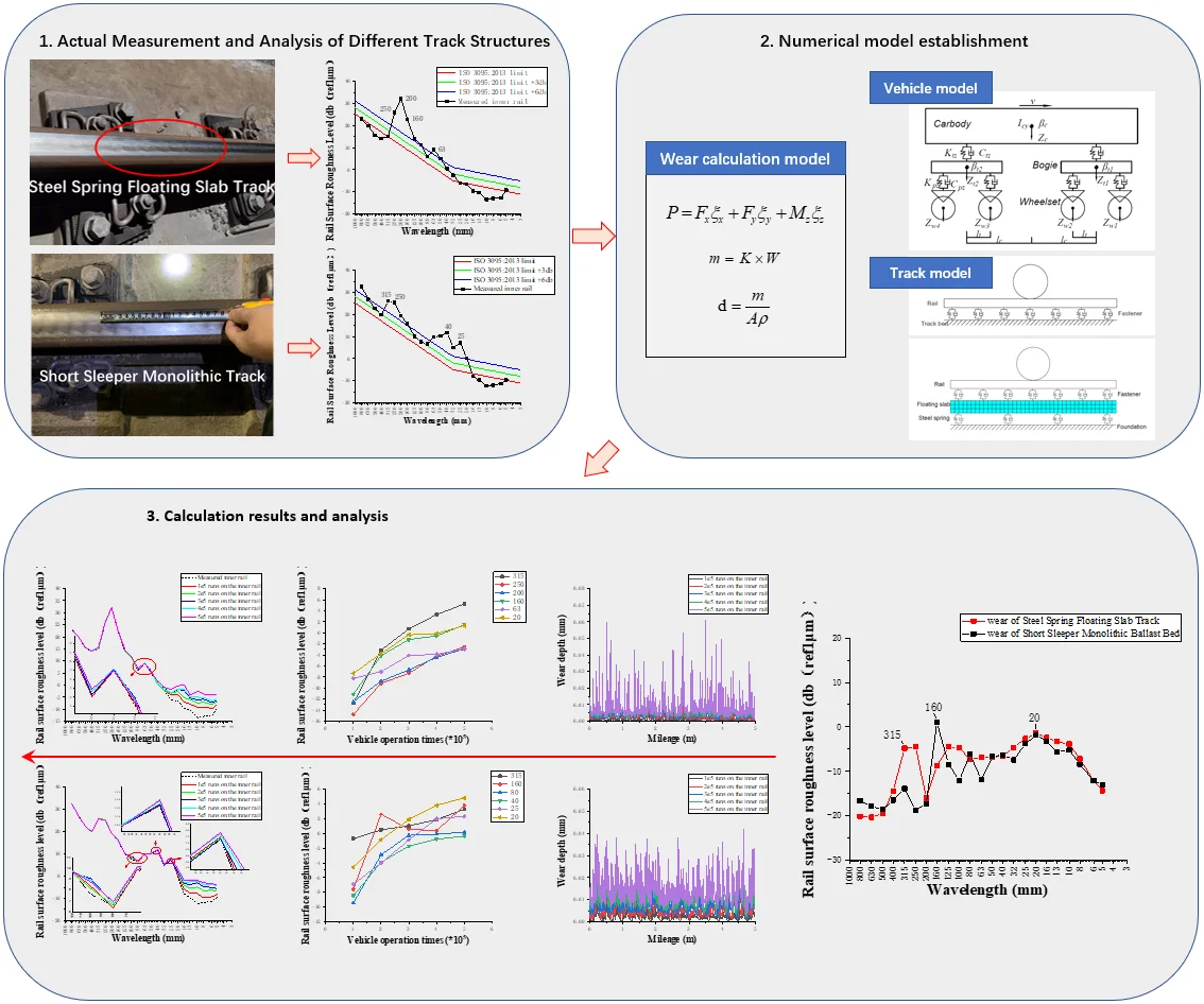
Abstract
Many studies have shown that the rail corrugation on the small radius curve section of subway floating slab track is serious. And it seems to be different from the rail corrugation on the common track. The track structure must play an important role in the generation and development of rail corrugation. This paper measured a subway line in Tianjin, including 2 different track structures, and analyzed the measured data by using the international evaluation and acceptance indexes of rail corrugation. The results show that the inner rail of short sleeper monolithic track (SSMT) has poor smoothness in the wavelength range of 0-300 mm, and the overall smoothness of outer rail is good; the inner rail of steel spring floating slab track (SSFST) has poor smoothness in the wavelength range of 100-300 mm, and the outer rail has poor smoothness in the wavelength range of 300-1000 mm. Then the vehicle-track coupling model and wheel-rail wear calculation model is established. The calculation results show that in the existing rail corrugation, the short-wavelength rail corrugation of 20-25 mm will continue to appear or deteriorate, and the development of rail corrugation of other wavelengths will slow down or stop to varying degrees; with the increase of train passing times, the rail corrugation of SSFST with the wavelength of 315 mm develops the fastest, and the rail corrugation of SSMT with wavelengths of 20 mm and 160 mm develops the fastest.
Highlights
- Field test of different track structures on the same line
- New evaluation index of wave wear
- Simulation of rail corrugation development
1. Introduction
Rail corrugation is a typical track disease. Its existence seriously affects the normal operation of vehicles and sharply reduces the comfort of passengers. In addition, the secondary environmental vibration and environmental noise caused by rail corrugation affect the surrounding buildings and residents, and even endanger the driving safety of rail vehicles.
At present, there have been many tests and research on the mechanisms and suppression measures of rail corrugation in the world.
Sato [1], from the Japanese Research Institute, has studied different corrugations around the world, and divided the local corrugations into short pitch corrugation of large radius curve or linear track, short pitch corrugation of small radius curve low rail and medium-wavelength corrugation of high rail and pointed out that the instability of wheel-rail normal contact force and creep force is the cause of short pitch corrugation of small radius curve low rail. Diana and Cheli [2] found that the rail corrugation on the metro line mainly occurs on the small radius curve, and there are significant differences in the development trend of rail corrugation on different track structures, and established two numerical models to reproduce the relevant characteristics of rail corrugation. At ERRI research site in the Netherlands, Martin Hiensch et al. [3] studied the cause of rail corrugation in only one of the two adjacent tracks through detailed metallurgical analysis and numerical simulation of vehicle-track dynamic interaction and considered that the low rail receptance of about 1200 Hz caused by sleepers is the possible reason of the rail corrugation.
In the past 40 years, various damping fasteners and track structures have emerged one after another. Among them, the damping effect of steel spring floating slab track (SSFST) is the most significant [4], which has been widely deployed in urban vibration sensitive areas. However, studies by various scholars show that abnormal rail corrugation caused by the use of track dampers [5-7] and SSFST [8-10] is widespread on subway lines in China. In order to solve these problems, scholars studied the wheel-rail contact and wear problems, trying to find out the causes of rail corrugation from a microscopic perspective.
Xiao et al. [11] investigated the development of rail corrugation for the four track structures by means of the wear growth rate. Among them, VAFT (vibration absorbing fastener track) is most likely to encounter rail corrugation; meanwhile, SSMT (short sleeper monolithic track) is most unlikely to encounter rail corrugation. Li et al. [12] used the Kik Piotrowski model to simulate wheel-rail contact and the Archard wear model to simulate rail wear, and studied the impact of train operation speed and passing number on rail wear of the small radius curve. The results show that the rail wear of the small radius curve increases with the increase of running speed and passing number; the rail wear decreases with the increase of the curve radius. Wang and Lei [13] studied the development characteristics of rail corrugation in the Cologne egg fastener section. It turned out that with the increase of train operation times, the rail corrugation corresponding to the characteristic frequency gradually formed and developed and the wavelength and development speed of the rail corrugation gradually increase with the increase of the train speed.
The research of the above scholars shows that the inner rail of the small radius curve section of subway is the place where the rail corrugation frequently occurs, and some SSFST also emerge serious rail corrugation. However, few research of rail/wheel wear focus on the impact of different track structures, especially on SSFST. Therefore, this paper investigates the rail surface irregularity of SSFST and short sleeper monolithic track (SSMT) in a small radius curve section of Tianjin Metro. A vehicle-track coupled numerical model and the wear calculation model are built to simulate the development of rail corrugation.
2. Measurement and evaluation index of corrugation
2.1. Field measurement
The line of the test section is a curve with a radius of 350 m, and there are two kind of track structures: short sleeper monolithic track (SSMT) and steel spring floating slab track (SSFST). The train running on the line is composed of 6 B-type vehicles, and the speed is about 54 km/h. The photos of on-site measured rail corrugation are shown in Fig. 1, and the short pitch corrugation can be seen with the naked eye.
Fig. 1Picture of on-site corrugation (source: Tianjin Metro Line 6)
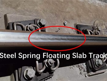
a) Steel spring floating slab track
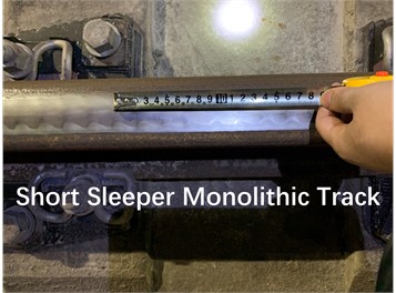
b) Short sleeper monolithic track
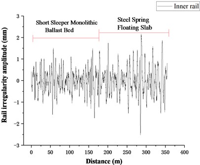
CAT corrugation acquisition instrument is used to measure the rail surface of the line. The rail irregularity amplitude is shown in Fig. 2. The maximum amplitude is about 2.5 mm, and the irregularity amplitude of steel spring floating slab section is higher than that of SSMT section.
Fig. 2Actual measured track irregularity
2.2. Evaluation index of rail corrugation
The current rail damage evaluation index of urban rail transit in China mainly refers to the repair rules of railway [14], in which the damage evaluation index for rail corrugation only includes parameters such as Wave Trough Depth, which is relatively single.
At present, the evaluation indexes of rail corrugation in the world are mainly based on:
1) Acoustics - Railway applications - Measurement of noise emitted by railbound vehicles (BS EN ISO3095: 2013) [15];
2) Railway Applications-Track-Acceptance of Works - Part3: Acceptance of Rail Grinding, Milling and Planning Work in Tracks (BS EN 13231-3:2006) [16];
3) Railway Applications-Noise Emission-Rail Roughness Measurement Related to Rolling Noise Generation (BS EN 15610:2009) [17].
Wherein, the key indexes are rail surface roughness level , moving average of peak-to-peak amplitudes (PPR) and moving average of root-mean-square (RMS) amplitudes.
2.3. Rail roughness level
The formula of rail roughness level is as follows:
wherein, – effective value of rail surface corrugation amplitude, μm; – reference value of roughness level of rail surface, 1 μm.
When the following two conditions exist, the rail irregularity level can be considered to exceed the standard: 1) the rail surface roughness level of a single wavelength exceeds the limit of BS EN ISO 3095:2013 by 6 dB; 2) the roughness level of three continuous wavelengths exceeds the limit of BS EN ISO 3095:2013 by 3 dB.
2.4. Acceptance standard for rail corrugation grinding
The calculation formula and schematic diagram of PPR and RMS are as follows:
where is the length of measurement and analysis window, and its specific value is shown in Table 1.
The specification divides the rail corrugation into 10-30, 30-100, 100-300, 300-1000 mm according to the wavelength, and gives the allowable limits of PPR and RMS respectively, as shown in Table 1.
Table 1Window length and allowable value of rail corrugation analysis
Wavelength / mm | / m | PPR limit / μm | RMS limit / μm |
10-30 | 0.15 | 10 | 4 |
30-100 | 0.5 | 10 | 4 |
100-300 | 1.5 | 30 | 12 |
300-1000 | 5 | 100 | 40 |
3. Actual measurement and analysis of different track structures
3.1. Short sleeper monolithic track (SSMT)
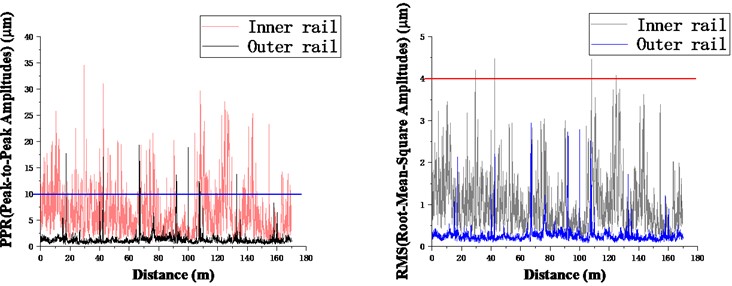
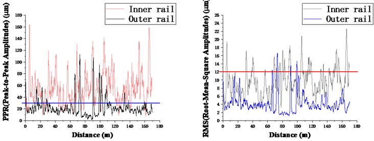
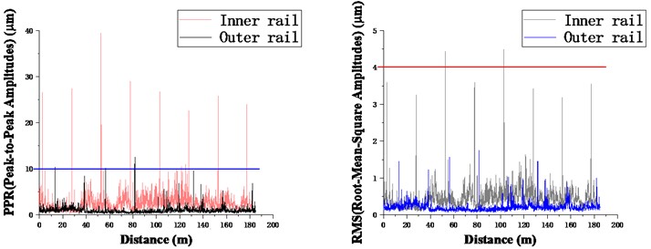
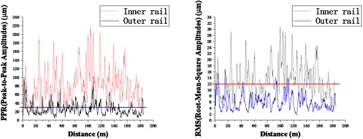
According to Fig. 2, the rail irregularity amplitude of SSMT in the test section is lower than that of floating slab track, and the maximum amplitude is about 1.6 mm. In order to further evaluate the rail corrugation of the line, this paper quotes the international rail corrugation acceptance standard. The standard classifies the irregularity data by the wavelength, and calculates PPR and RMS introduced above. The calculation results are shown in Fig. 3.
Fig. 3Curves of PPR and RMS with mileage in SSMT section
a) 10-30 mm
b) 30-100 mm
c) 100-300 mm
d) 300-1000 mm
Overall, the PPR and RMS of the inner rail are mostly higher than that of the outer rail. The PPR of the inner rail generally exceeds the acceptance limit of rail corrugation grinding in the wavelength range of 10-300 mm (i.e. the horizontal line in the figure), and the RMS value of the inner rail is generally less than the limit. The PPR and RMS values of the outer rail in the four wavelengths ranges are generally less than the limit, but there are still several peaks greatly exceeding the limit in the wavelength ranges of 30-100 mm and 300-1000 mm. The Data shows that, in contrast, the inner rail smoothness of the SSMT section is poor, which is mainly in the wavelength range of 10-300 mm; the overall smoothness of the outer rail is good, but there are several serious wear in the medium and long wave ranges.
Fig. 4One-third octave wavelength diagram of rail roughness level of SSMT
a) Inner rail
b) Outer rail
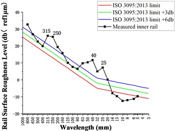
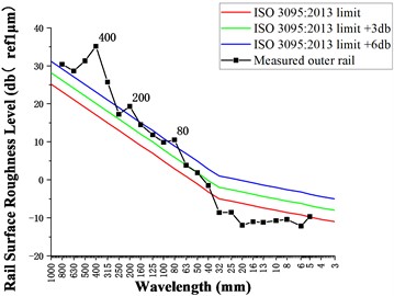
The calculation results of rail roughness level are shown in Fig. 4. The amplitude of inner rail roughness level fluctuates greatly, and there are multiple values out of limit. The characteristic wavelengths of the inner rail are 25-63 and 200-315 mm. The outer rail roughness level is prominent in the long wavelength band, and the characteristic wavelengths of the outer rail are 315-500, 200 and 80 mm.
3.2. Steel spring floating slab track (SSFST)
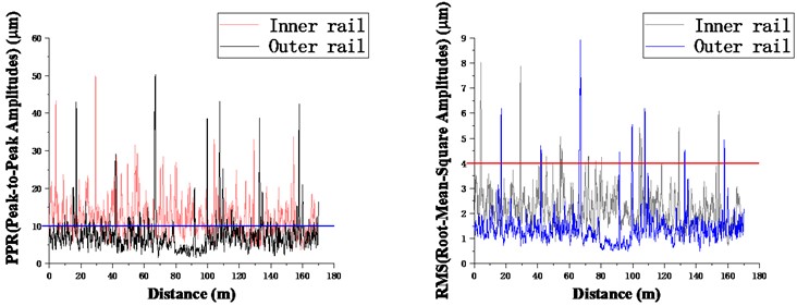
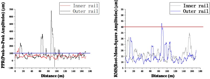
According to Fig. 2, the irregularity amplitude of the SSFST in this test section is higher, and the maximum amplitude is about 2.5 mm.
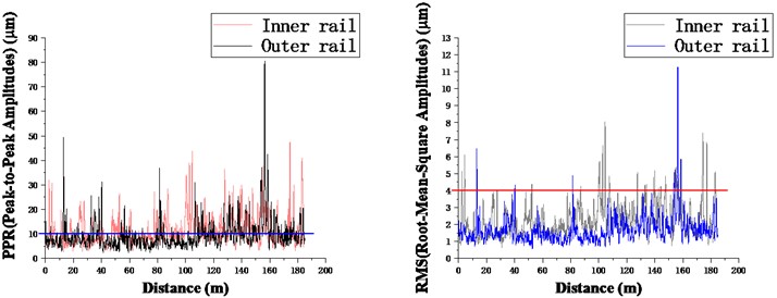
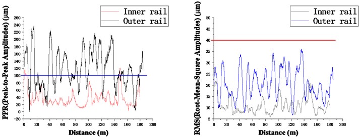
The calculation results of PPR and RMS of SSFST section are shown in Fig. 5. It can be seen from the figure that the PPR and RMS values of the inner rail are higher than those of the outer rail in the wavelength range of 10-30 mm and 100-300 mm, the two indexes of inner rail and outer rail are relatively close in the wavelength range of 30-100 mm, while the PPR and RMS values of the outer rail are much higher than those of the inner rail in the wavelength range of 300-1000 mm. Therefore, it can be considered that the inner rail of small radius curve section of SSFST is prone to emerge short pitch corrugation, while the outer rail is prone to emerge medium-wavelength and long-wavelength corrugation.
Specifically, the PPR of inner rail exceeds the limit only at the form of periodic pulses in the wavelength range of 10-30 mm. The exceeding limit is more serious in the wavelength range of 30-300 mm, especially in the wavelength range of 100-300 mm. However, it is generally lower than the limit in the wavelength range of 300-1000 mm. Besides, The RMS of the inner rail seriously exceeds the limit in the wavelength range of 100-300 mm, and the RMS in other wavelength ranges is generally low. On the contrary, The PPR of outer rail is seriously out of limit in the wavelength range of 300-1000 mm, followed by the wavelength range of 30-100 mm. The RMS of the outer rail are all below the limit. The above data shows that the inner rail of SSFST has poor smoothness in the range of 100-300 mm, and the outer rail has poor smoothness in the range of 300-1000 mm.
Fig. 5Curve of PPR and RMS with mileage in SSFST section
a) 10-30 mm
b) 30-100 mm
c) 100-300 mm
d) 300-1000 mm
It can be seen from Fig. 5(a) that there are periodic sharp fluctuations in the 10-30 mm, with a period of about 25 m, which is consistent with the length of steel spring floating slab. It can be considered that the uneven support at the slab joint leads to abnormal vertical vibration between wheel and rail, resulting in short pitch corrugation, but the vibration decays rapidly and disappears.
Fig. 6Schematic diagram of slab joint
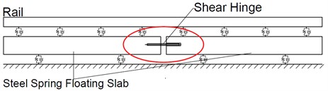
Fig. 7One-third octave wavelength diagram of rail roughness level of SSFST

a) Inner rail
b) Outer rail
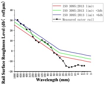
The calculation of rail roughness level of SSFST section is shown in Fig. 7. Compared with outer rail, the inner rail roughness level is higher. The four significant exceedance values are 250, 200, 160 and 63 mm. The outer rail roughness level is low and does not exceed the limit.
3.3. Comparative analysis of two track structures
Since the PPR and RMS values of the outer rail of the two track structures are less out of limit, only the PPR and RMS out of limit ratio of the inner rail are calculated and listed in Table 2.
The calculation results of evaluation indexes of the two track structures are integrated as shown in Table 2. The comparative analysis shows that:
(1) According to the analysis of PPR overrun ratio, the rail corrugation of each wavelength range appears on the SSMT section. Except 300-1000 mm, the larger the wavelength is, the higher the overrun ratio is, that is, the probability of long wavelength corrugation is higher. The corrugation of SSFST is the most serious in the wavelength range of 100-300 mm, and the PPR overrun ratio is as high as 94.90 %.
(2) From the perspective of PPR and RMS, the rail corrugation of SSFST in the wavelength range of 100-300 mm is worse than that of SSMT, on the contrary, the rail corrugation in the wavelength range of 10-30 and 30-100 mm is better than that of SSMT.
(3) According to the one-third octave wavelength diagram of rail roughness level, the actual curve lines of the two track structures have serious corrugation on the inner rail and have different characteristic wavelengths. In terms of the overrun degree, the main characteristic wavelength of the SSFST section is 200 mm, and the secondary characteristic wavelength is 160, 250 and 63 mm. The main characteristic wavelength of the inner rail in the SSMT section is 40 mm, and the secondary characteristic wavelengths are 315, 250 and 25 mm. There is no corrugation on the outer rail of the SSFST section. The main characteristic wavelength of the outer rail of the SSMT section is 400 mm, and the secondary characteristic wavelength is 200 and 80 mm.
Table 2PPR and RMS overrun ratio of two track structures
Index | Structure | 10-30 Mm | 30-100 mm | 100-300 mm | 300-1000 mm |
PPR | SSMT | 13.55 % | 48.27 % | 78.79 % | 3.6 % |
SSFST | 0.68 % | 34.81 % | 94.90 % | 3.0 % | |
RMS | SSMT | 0 | 1.2 % | 14.5 % | 0 |
SSFST | 0 | 1.7 % | 43.3 % | 0 | |
Characteristic wavelength | SSMT | 25 | 40 | 250, 315 | / |
SSFST | / | 63 | 160, 200, 250 | / |
4. Numerical model and wear calculation
4.1. Vehicle-track coupled model
The vehicle model consists of one carriage, two bogies and four wheelsets. Fig. 8 shows the schematic diagram of vehicle model.
The track model is composed of rails, fasteners, and track bed. The rail is model as the Timoshenko beam, the fastener can consider stiffness and damping in three directions, and the track bed is described by the finite element method.
Kik-Piotrowski calculation model is adopted for wheel-rail contact modeling, which can consider the multi-point contact. Vehicle and track model parameters can refer to the relevant literatures (Lei et al. [18]; Li and Ren [19]; Wen [20]).
4.2. Wear model
According to the friction power theory, wear only occurs in the sliding area of the contact patch, and the wear amount is directly proportional to the friction work, that is:
where, is the wear mass, is the friction work and is the wear coefficient.
Fig. 8Railway vehicle model
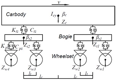
Fig. 9Schematic diagram of track model
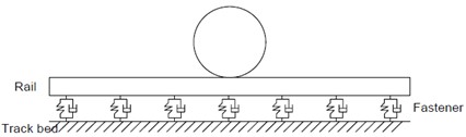
a) Short sleeper monolithic track
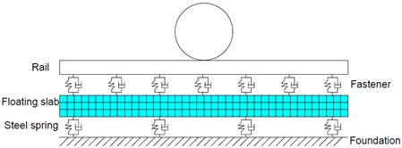
b) Steel spring floating slab track
The friction power is calculated from the sum of the product of creep force and creepage in all directions in the contact patch:
where is the longitudinal creep force, is the lateral creep force, is the creep moment, is the longitudinal creepage, is the lateral creepage, is the spin.
By calculating the friction work and wear amount varying with the mileage, the wear depth of rail when the vehicle passes through can be obtained:
where is the contact area and is the material density.
4.3. Rail Wear development calculation
According to the actual measurement above, the inner rail corrugation is more serious. Furthermore, the wear model used in this paper is more suitable for the rail head wear of the inner rail in this metro curve line, and the multi-point wear of the outer rail. Therefore, this section only focuses on the rail corrugation development characteristics of inner rail in this metro line.
Moreover, since the wear amount generated by a single vehicle operation is very small, this paper takes 100000 vehicle operations as an output order, calculates the wear by using SSMT model and SSFST model respectively, and outputs the rail wear depth curves after 100000, 200000, 300000, 400000 and 500000 vehicle operations, as shown in Fig. 10.
Fig. 10Rail wear development curve
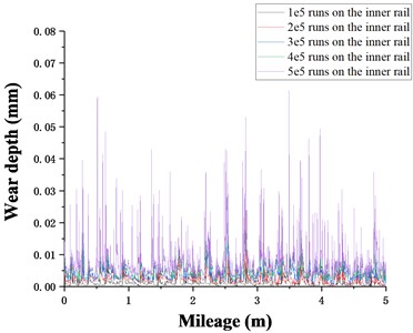
a) Steel spring floating slab track
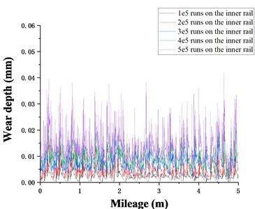
b) Short sleeper monolithic track
The maximum wear depth of SSFST inner rail is about 0.06 mm, and the maximum wear depth of SSMT section inner rail is about 0.04 mm. The one-third octave spectrum analysis for each renewal irregularity is carried out, as shown in Fig. 11. After the train runs for many times in the SSFST section, the development speed of the original corrugation with the wavelength of 200 mm and 63 mm slows down or stops. In the section of SSMT, there is a significant increase in the wavelength sections of 20 mm and 40-100 mm. Therefore, it can be preliminarily considered that the two track structures have different corrugation development trends. The measured corrugation with main characteristic wavelength of SSFST may not develop, while the measured short pitch corrugation of SSMT section has a deterioration trend.
Fig. 11One-third octave wavelength diagram of rail wear depth level
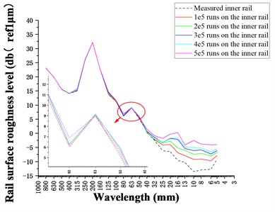
a) Steel spring floating slab track
b) Short sleeper monolithic track
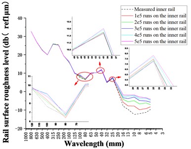
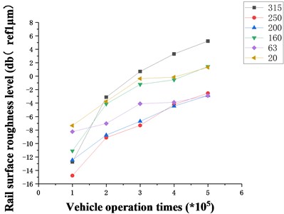
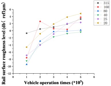
In order to further explore the influence of the two track structures on the development of rail corrugation, the rail wear roughness level is calculated based on the rail wear model in this paper, as shown in Fig. 12. The wear amplitude of SSFST is generally high, reaching the peak at the wavelengths of 20 mm, 125 mm and 250-315 mm, while the wave trough appears at the characteristic wavelength of the measured corrugation, especially at the wavelength of 200 mm, and its amplitude is as low as –16 dB (Ref 1 μm) It shows that the development speed of the original corrugation of 63 mm and 200 mm wavelength has slowed down or stopped. In the SSMT section, the amplitude at the 20 mm wavelength is higher and reaches the maximum at the 160 mm wavelength, while the 315 mm of the original measured corrugation characteristic wavelength also shows a wave peak, but the amplitude is lower, indicating that the original corrugation at the 250-315 mm wavelength develops slowly or stops developing, while the corrugation at the 20 mm wavelength will continue to develop, and a new corrugation with 160 mm wavelength may appear.
Fig. 12Comparison diagram of wear of two track structures
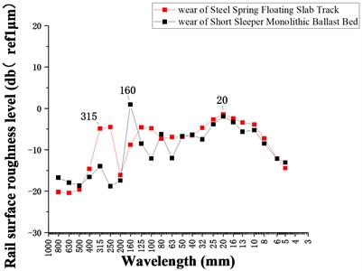
Fig. 13Curve of rail wear depth grade with train operation times
a) Steel spring floating slab track
b) Short sleeper monolithic track
The measured characteristic wavelength and several wavelengths with the highest amplitude are selected to compare and analyze the rail wear roughness level every 100000 times, as shown in Fig. 13. It is easy to find that the corrugation of SSFST with the wavelength of 315 mm develops the fastest, and the corrugation of short sleeper monolithic ballast with wavelengths of 20 mm and 160 mm develops the fastest. In addition, among the measured characteristic corrugation, the rail roughness level with the wavelength of 25 mm rises rapidly, while the others are at a low level, indicating that the development of the original measured characteristic corrugation has slowed down or stopped to varying degrees except for the corrugation with the wavelength of 25 mm.
The accuracy of the wear amount calculated by the simulation is closely related to the parameters of each component of the vehicle-track coupling system. Because the dynamic model is simplified more than the actual situation, the simulation results are only for reference. In general, wear increment can be used as a quantitative index to evaluate the development of rail surface wear, and further guide rail grinding and other maintenance operations.
5. Conclusions
In view of the rail corrugation phenomenon in the small radius curve section of a metro line in Tianjin, the corrugation characteristics of different track structures are analyzed through the measured data, and a numerical simulation model is established to calculate the development trend of the rail corrugation, which provides a measured case for the further study of the rail corrugation, and also provides a theoretical basis for the rail maintenance of the metro line.
1) The damage evaluation index of rail corrugation in China is defective. In this paper, the current international rail grinding acceptance standard is used to evaluate the damage degree of rail corrugation. After analysis, the inner rail of SSMT has poor smoothness in the wavelength range of 10-300 mm, and the overall smoothness of outer rail is good. The inner rail of SSFST has poor smoothness in the wavelength range of 100-300 mm, and the outer rail has poor smoothness in the wavelength range of 300-1000 mm.
2) The periodic fluctuation of PPR value in the 10-30 mm section shows that in the SSFST section, the uneven support at the joint of the floating slab leads to abnormal vertical vibration between the wheel and rail, resulting in short-wavelength rail corrugation, but it decays quickly and disappears.
3) According to the analysis of the PPR & RMS overrun ratio, on the SSMT, the larger the wavelength, the larger the overrun ratio, reaching the peak of 78.79 % in the 100-300 mm wavelength range. The rail corrugation of SSFST is the most serious in the wavelength range of 100-300 mm, and the PPR overrun ratio is as high as 94.90 %.
4) Taking the measured data as the initial irregularity for simulation calculation, the results show that the medium and short pitch corrugation of the SSMT develops faster, and the medium-wavelength and long-wavelength corrugation of the SSFST develops faster. Among them, with the increase of train passing times, the rail corrugation with 315mm wavelength develops fastest on SSFST, and the rail corrugation with 20 mm and 160 mm wavelength develops fastest on SSMT. In addition, except for the 25 mm short wavelength, the development of the measured characteristic corrugation has slowed down or stopped to varying degrees.
References
-
Y. Sato, A. Matsumoto, and K. Knothe, “Review on rail corrugation studies,” Wear, Vol. 253, No. 1-2, pp. 130–139, Jul. 2002, https://doi.org/10.1016/s0043-1648(02)00092-3
-
G. Diana, F. Cheli, S. Bruni, and A. Collina, “Experimental and numerical investigation on subway short pitch corrugation,” Vehicle System Dynamics, Vol. 29, No. sup1, pp. 234–245, Jan. 1998, https://doi.org/10.1080/00423119808969562
-
M. Hiensch, J. C. O. Nielsen, and E. Verheijen, “Rail corrugation in The Netherlands-measurements and simulations,” Wear, Vol. 253, No. 1-2, pp. 140–149, Jul. 2002, https://doi.org/10.1016/s0043-1648(02)00093-5
-
J. T. Nelson, “Recent developments in ground-borne noise and vibration control,” Journal of Sound and Vibration, Vol. 193, No. 1, pp. 367–376, May 1996, https://doi.org/10.1006/jsvi.1996.0277
-
W. N. Liu, J. Ren, W. F. Liu, W. B. Wang, and H. G. Zhang, “In-situ tests and analysis on rail corrugation of Beijing Metro,” (in Chinese), Urban Rapid Rail Transit, Vol. 24, No. 3, pp. 6–9, 2011.
-
X. L. Cui, S. Yan, and G. X. Chen, “Field measurement and numerical simulation for rail corrugation in sector of fixed dual short sleeper,” (in Chinese), Journal of Vibration and Shock, Vol. 37, No. 13, pp. 171–176, 2018, https://doi.org/10.13465/j.cnki.jvs.2018.13.027
-
X. Jin, W. Li, Z. Wen, H. Wang, and X. Sheng, “An investigation into rail corrugation, its mechanisms and effects on the dynamic behavior of metro trains and tracks in China,” International Journal of Railway Technology, Vol. 5, No. 3, pp. 1–29, 2016.
-
Y. H. Zhong, Q. H. Guan, Z. F. Wen, W. Li, G. Q. Tao, and Q. Zhang, “Influence of metro rail corrugation on track system’s vibration and mitigation characteristics,” Noise and Vibration Control, Vol. 37, No. 4, pp. 85–89, 2017.
-
X. Li, Z. S. Ren, and N. Xu, “Study on rail corrugation of steel spring floating slab track on subway with small radius curve track,” Journal of China Railway Society, Vol. 39, No. 8, pp. 70–76, 2017.
-
C.-M. Kuo, C.-H. Huang, and Y.-Y. Chen, “Vibration characteristics of floating slab track,” Journal of Sound and Vibration, Vol. 317, No. 3-5, pp. 1017–1034, Nov. 2008, https://doi.org/10.1016/j.jsv.2008.03.051
-
H. Xiao, S. Yang, H. Wang, and S. X. Wu, “Initiation and development of rail corrugation based on track vibration in metro systems,” Proceedings of the Institution of Mechanical Engineers, Part F: Journal of Rail and Rapid Transit, Vol. 232, No. 9, pp. 2228–2243, Oct. 2018, https://doi.org/10.1177/0954409718768956
-
H. Li, J. L. Sun, and G. T. Zhao, “Research on rail wear of small radius curve in EMU depot,” China Railway Science, Vol. 41, No. 6, pp. 39–51, 2020, https://doi.org/10.3969/j.issn.1001-4632.2020.06.05
-
Z. Q. Wang and Z. Y. Lei, “Formation and mechanism and development properties of rail corrugation of cologne egg fastener section,” Journal of Vibration, Measurement and Diagnosis, Vol. 41, No. 4, pp. 688–694, 2021, https://doi.org/10.16450/j.cnki.issn.1004-6801.2021.04.008
-
“Railway line repair rules. Ty No. 146,” (in Chinese), Ministry of Railways of the PRC, China Railway Publishing House, Beijing, 2006.
-
“Acoustics-Railway Applications-Measurement of Noise Emitted by Railbound Vehicles,” BS EN ISO3095:2013, European Committee for Standardization, British Standards Institution, 2013.
-
“Railway Applications-Track – Acceptance of Works-Part3: Acceptance of Rail Grinding, Milling and Planning Work in Tracks,” BS EN 13231-3:2006, European Committee for Standardization, British Standards Institution, 2006.
-
“Railway Applications-Noise Emission-Rail Roughness Measurement Related to Rolling Noise Generation,” BS EN 15610: 2009, European Committee for Standardization, British Standards Institution, 2009.
-
Z. Y. Lei, Z. Q. Wang, L. Li, and C. Z. Geng, “Rail corrugation characteristics of the common fastener track in metro,” Natural Science, Vol. 47, No. 9, pp. 1334–1340, 2019.
-
X. Li and Z. S. Ren, “Study on the vertical vibration characteristics of steel spring floating slab track in subway,” Journal of South China University of Technology, Vol. 46, No. 12, pp. 103–110, 2018.
-
S. M. Wen, “Study on rail grinding profile for small radius curved track of metro line,” (in Chinese), MSc Thesis, Southwest Jiaotong University, Sichuan, China, 2018.
About this article

The authors have not disclosed any funding.
The datasets generated during and/or analyzed during the current study are available from the corresponding author on reasonable request.
The authors declare that they have no conflict of interest.
