Abstract
In order to study the influence of harmonics on the vibration and noise of permanent magnet synchronous motor, this paper introduces an analysis method based on field-circuit coupling, and establishes a complete analysis process from the control strategy to the vibration and noise response of the motor. Firstly, the coupling model including control strategy, main circuit model and electromagnetic field model is established. Secondly, the finite element model of the permanent magnet synchronous motor under the influence of coupling is established to analyze and compare the electromagnetic force wave characteristics of the coupling excitation and the sinusoidal excitation. Then, the coupled electromagnetic force is loaded into the structural field to simulate and calculate the vibration and noise. Finally, the effectiveness of the model is verified through experimental sound pressure level comparison under steady-state and speed-up conditions, and it provides a reference for vibration and noise prediction of the motor system.
1. Introduction
Permanent magnet synchronous motor (PMSM), as a new type of driving mode, is widely used in electric vehicles due to its advantages of high efficiency, high power density, wide speed range and so on [1], [2]. Meanwhile, its vibration and noise problems have become increasingly prominent [3]. At present, for the analysis of electromagnetic vibration and noise of PMSM, the finite element method (FEM) is often used to simulate the actual vibration and noise of the motor [4]-[6]. However, FEM mostly uses sinusoidal current excitation, it cannot accurately simulate the impact of high-frequency current harmonics on the vibration and noise of the motor when the inverter is powered [7], [8].
In [9], the finite element calculation and sound field analysis of the motor carried out by artificial harmonic injection method. The analysis shows that when there are low-order harmonic currents in the motor windings, the vibration and noise of the motor will be reduced. In [10], the paper proposes a multi-physical model and establish a noise transfer function to predict the electromagnetic noise of PMSM with a variable speed range and analyze its sound quality. This paper in [11] describes the electromagnetic force caused by the different winding types by using a circuit simulator and 2D finite element model to study the vibration and noise generated by the different windings. The paper [12] uses the finite element model to analyze the output characteristics of the motor under different slot/pole combinations, and uses the generated radial electromagnetic force to study the vibration and noise of the motor, it provides a reference for the design of the slot/pole of the motor. In [13], the field reconstruction method is used to analyze PMSM torque ripple and noise performance under two faults of permanent magnet static eccentricity and partial demagnetization. The average torque, torque ripple and noise under normal and fault conditions are compared to analyze the sound power. In reference [14], the influence of PMSM number of slots and number of poles on the vibration and noise in the design stage is studied. The vibration characteristics of the motor with different slot number and pole number combinations are analyzed by FEM, and the optimal combination mode is obtained according to the results. In order to reduce the vibration noise of PMSM, starting from the motor structure, the magnetic field of the motor can be optimized by changing the slot structure of the motor rotor, so as to improve the electromagnetic vibration force of the stator teeth and reduce the electromagnetic vibration noise of the motor [15]. In summary, many scholars have started their research on vibration and noise of motor mainly from the input of the inverter and the body structure [16]-[19].
This paper firstly analyzes the structure of the field-circuit coupling model, calculate the radial electromagnetic force wave in the space distribution and time history of an 8-pole 48-slot PMSM. And the calculated electromagnetic force is compared with that of sinusoidal excitation by Fourier transform. Then the constrained modes of stator system are analyzed by modal superposition method. Meanwhile, the radial electromagnetic force is used as the excitation to calculate the electromagnetic vibration noise of PMSM. Finally, the correctness of the proposed model is verified by comparing with the spectrum of the experimental sound pressure level (SPL). This method can be used to predict the electromagnetic vibration and noise of motor in the early stage of motor research, so as to shorten the development cycle.
2. Simulation analysis of electromagnetic force under field-circuit coupling method
2.1. Construction and simulation analysis of field-circuit coupling model
A field-circuit coupling analysis model is established with PMSM for a vehicle. Motor parameters are shown in Table 1, and the field-circuit coupling structure is shown in Fig. 1.
Table 1Motor parameters
Name | Value | Name | Value |
Rated power | 68 kw | Peak torque | 310 nm |
Rated torque | 174 nm | Maximum speed | 12000 rpm |
Bus voltage | 460 v | Pole pairs | 4 |
Peak current | 320 a | Number of slots | 48 |
Fig. 1Field-circuit coupling structure
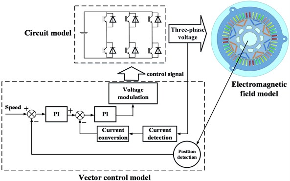
The motor control model, main circuit model and electromagnetic field model are co-simulated. The main circuit model is built by Simplorer, the motor control algorithm model is built in Matlab/Simulink, and the electromagnetic analysis model is built in Maxwell.
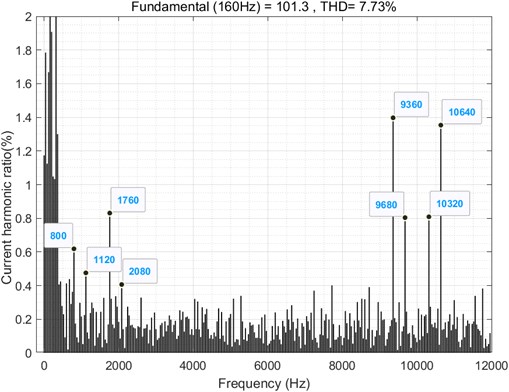
Set the speed to 2400 rpm and the load torque to 58 N∙m, the current fundamental frequency 160 Hz, the switching frequency 10 kHz. The simulation results of the current spectrum analysis are shown in the Fig. 2. It can be seen that the low-frequency harmonic components mainly include the 5th harmonic (800 Hz), the 7th harmonic (1120 Hz), the 11th harmonic (1760 Hz), the 13th harmonic (2080 Hz) and the high-frequency harmonics related to the switching frequency (, ), the frequencies are 9360 Hz, 9680 Hz, 10320 Hz and 10640 Hz, respectively.
Fig. 2A-phase current spectrum
2.2. Comparison of calculation results of radial electromagnetic force
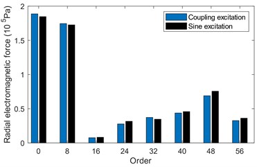
In order to compare the calculation results of field-circuit coupling excitation and standard sinusoidal excitation, the radial electromagnetic force varying with time and space is analyzed.
It can be seen from Fig. 3(a), the main orders of radial electromagnetic force are 0th, 8th, 16th, 24th, 32th, 40th, 48th and 56th respectively. They are multiples of the number of poles, and the amplitude difference between the two excitations is very small.
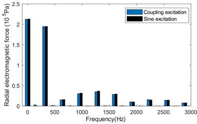
Similarly, the time-varying electromagnetic force generated by the two excitation is extracted for comparison. Due to the longer bandwidth, the frequency spectrum is divided into three sections: 0 Hz-3000 Hz, 3000 Hz-8000 Hz and 8000 Hz-12000 Hz. It can be seen from Fig. 3(b)-(d) that the amplitude difference of the radial air gap electromagnetic force with time generated by the two excitations is very small in the range of 0 Hz-8000 Hz. While the amplitude difference is relatively large in the range of 8000 Hz-12000 Hz. The main frequency differences are shown in Table 2. It can be found that the amplitude of coupled excitation is more than ten times larger than that of sinusoidal excitation, mainly because the high-frequency component is related to the switching frequency which are , , , respectively.
Table 2Frequency differences
Frequency (Hz) | Coupling excitation amplitude (Pa) | Sine excitation amplitude (Pa) | Error (%) |
9200 | 1289 | 80.72 | 1497 |
9520 | 2220 | 113.2 | 1861 |
10480 | 1715 | 125.3 | 1269 |
10800 | 1081 | 59.8 | 1708 |
11120 | 874.1 | 43.66 | 1902 |
Fig. 3Spectrum of radial electromagnetic force varying in space and time
a) Space electromagnetic force spectrum
b) 0 Hz-3000 Hz spectrum
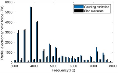
c) 3000 Hz-8000 Hz spectrum
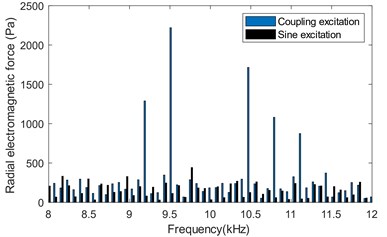
d) 8000 Hz-12000 Hz spectrum
3. Simulation analysis of electromagnetic vibration and noise
This section mainly studies the electromagnetic vibration and noise radiation caused by the radial electromagnetic force generated by the field circuit coupling method.
3.1. Modal analysis of stator system
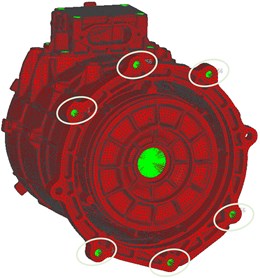
The electromagnetic vibration noise of PMSM is determined by the radial electromagnetic force wave acting on the stator structure and the radial modes of the stator structure. In this paper, the vibration and noise of the motor are carried out on the bench, so the six degrees of freedom of the cross-section bolt holes are constrained according to the actual constraints to simulate the motor installation state, as shown in Fig. 4.
Fig. 4Boundary constraints for stator systems
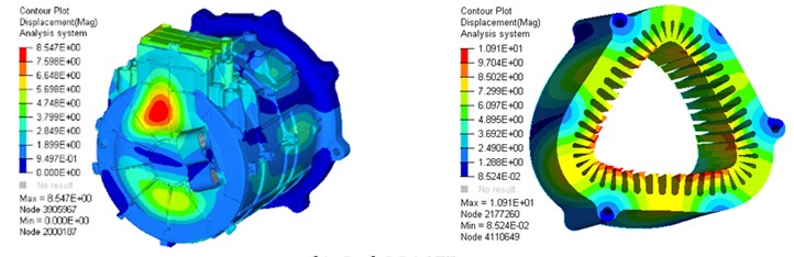
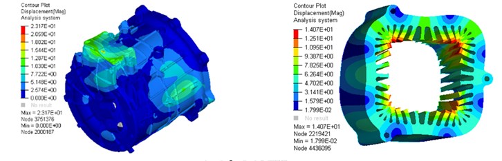
Add boundary conditions to simulate the constrained modes of the motor. This article lists the first five radial modes and frequencies of the stator system, which are shown in Fig. 5. The left is the vibration mode of the stator system, and the right is the vibration mode of the stator core.
Fig. 5The first five constrained modes of the stator system
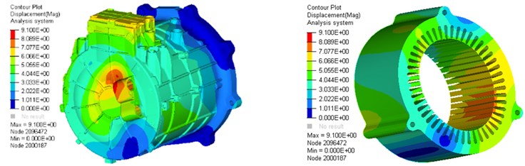
a) 2nd 1136 Hz
b) 3rd 2310 Hz
c) 4th 3497 Hz
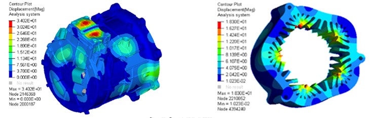
d) 5th 4522 Hz
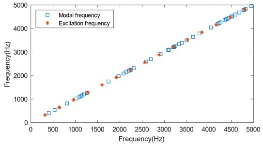
The main radial electromagnetic force frequency of the motor is an even multiple of the current frequency. As can be seen from Fig. 6, when the excitation frequency is close to the modal frequency of the stator system, it will cause the stator system to resonate, especially in 960 Hz and 1280 Hz, the stator modal frequencies are dense, which are easy to cause the resonance of stator system. Although, the excitation frequency after 1920 Hz is in the modal dense area, its excitation energy is small, which is not easy to arouse the mode of the motor.
Fig. 6Scatter plot of excitation frequency and modal frequency
3.2. Simulation analysis of electromagnetic vibration
The electromagnetic vibration of PMSM can be analyzed by the modal superposition method. The radial electromagnetic force is applied to the finite element model of the motor structure as a load to calculate the electromagnetic vibration induced by the radial electromagnetic force generated by the field-circuit coupling method. Since low-frequency vibration is generally considered in engineering, electromagnetic vibration frequency of motors below 3500 Hz is mainly analyzed. The motor vibration collection point and collection point vibration acceleration spectrum are shown in Figs. 7 and 8.
Fig. 7Vibration collection point
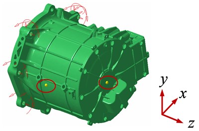
Fig. 8Collection point vibration acceleration spectrum
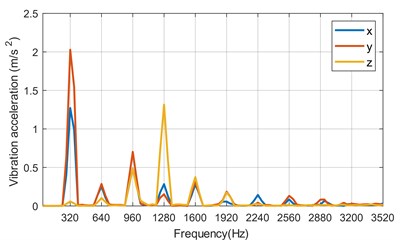
a) Housing vibration acceleration spectrum
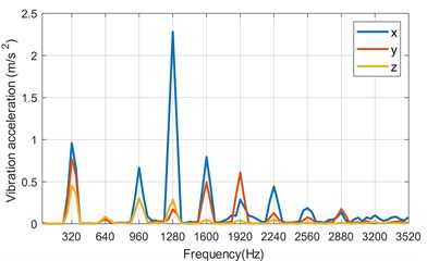
b) Endcap vibration acceleration spectrum
The main vibration frequencies of the housing and endcap are 320 Hz, 960 Hz and 1280 Hz. Because of the large amplitude of radial electromagnetic force at 320 Hz, it is easier to excite the mode of the stator system. At 960 Hz and 1280 Hz, the stator system resonance is excited due to the dense stator system modes. Although the modes are denser at 2000 Hz-3500 Hz, the vibration amplitude of the stator system is relatively small and the energy is low. It is not easy to excite the modes of the motor.
3.3. Simulation analysis of electromagnetic noise radiation
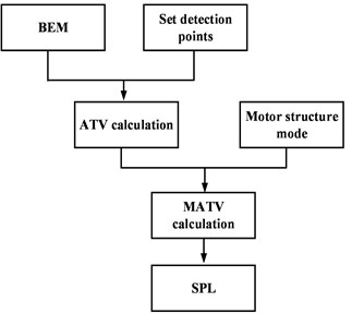
The boundary element model (BEM) of the motor is established. The simulation analysis frequency is 12000 Hz, and the grid size cannot exceed 5 mm. Set the field point sound pressure grid as a square 1 m away from the center of the motor, and select the position of the detection point, as shown in Fig. 9. Then the acoustic transfer vector (ATV) is calculated, combine the vibration acceleration calculated above and the motor structure mode to solve the model acoustic transfer vector (MATV) [20]. Finally, the SPL of the detection point can be obtained, the analysis process is shown in Fig. 10.
Fig. 9Outside sound field model of motor
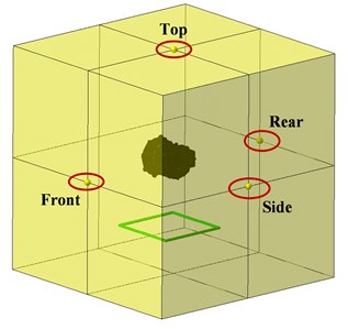
Fig. 10MATV analysis process
4. Analysis and verification of experimental results
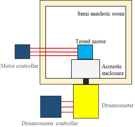
In order to verify the correctness of the vibration and noise model of PMSM based on the field-circuit coupling, the motor noise experiment was carried out in an acoustic environment. The test conditions are shown in Table 3. Noise is measured in a semi-anechoic room using the near-field method. For the motor with the barycenter axis height greater than 225 mm, the equivalent rectangular envelope surface method is used to measure the sound field and sound pressure, the measuring point is 1m away from the motor, as shown in Fig. 11. In order to eliminate the influence of vibration and noise on motor test results in the experiment equipment installation, the layout of test equipment is shown in Fig. 12.
Fig. 11Location of noise measuring points
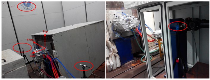
Table 3Test conditions
Condition | Rotation rate (rpm) | Torque (Nm) |
Steady speed | 2400 | 58 |
Speed-up | 750-5000 | 58 |
Fig. 12Layout of test equipment
As Fig. 13 shows, the main noise frequency of the motor is the double frequency of the current frequency and its integer multiple, such as 320 Hz, 960 Hz, 1920 Hz, 3040 Hz, 5760 Hz, and the high frequency, such as 9200 Hz, 9520 Hz, 10480 Hz and 10800 Hz, which are consistent with the frequency obtained from the electromagnetic vibration noise analysis under field-circuit coupling.
Fig. 13Noise spectrum of steady speed conditions
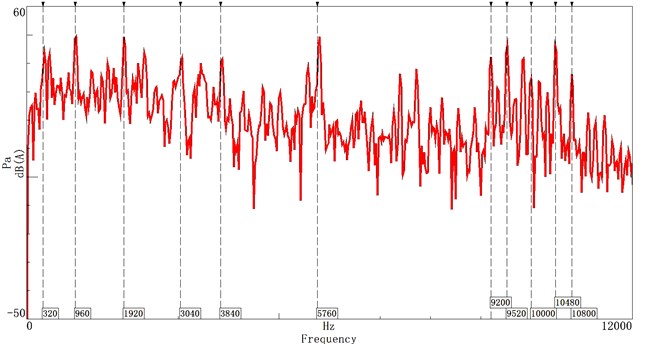
Fig. 14 shows that the main orders of the motor noise are 8th, 16th, 24th, 32th, 40th, 48th, 72th, 96th, and 144th. The electromagnetic force is an integer multiple of the number of poles of the motor. And the high-frequency noise is mainly distributed around 10000 Hz, showing a ‘radial’ distribution, which is related to the switching frequency. It can also be seen that resonance bands appear near 1689 Hz, 3077 Hz, and 5537 Hz. And below 3000 Hz, the resonance band is very wide. This is because the modalities of the motor below 3000 Hz are dense, and the amplitude of the integral multiple order excitation of the motor poles is high, which arouses the modalities of the motor, resulting in the increase of the noise amplitude below 3000 Hz.
Fig. 14Noise colormap of speed-up condition
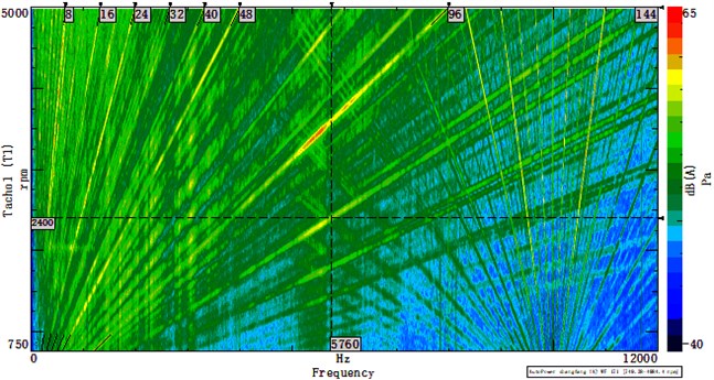
Fig. 15Comparison of sound pressure level spectrum at detection point
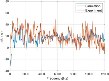
a) Top
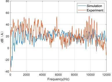
b) Front
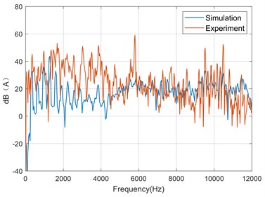
c) Side
d) Rear
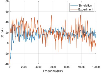
It can be seen from Fig. 15 that within 0 Hz-6000 Hz, the frequency with a higher sound pressure level is an even multiple of the current frequency. Within 6000 Hz-12000 Hz, the frequency with a higher sound pressure level is mainly related to the switching frequency, and these frequency components are the main contribution of the high frequency noise of the motor. However, there are still large errors at 5760 Hz and other frequencies, mainly because the model only considers the radial electromagnetic force, ignores the tangential and axial electromagnetic force, and does not consider the vibration and noise caused by the imbalance between bearing and rotor and the coupling of temperature field. The basic trends of simulation data and experimental data are roughly the same, which verifies the validity of the model.
Future research will focus on the neglected parts of the previous work to improve the accuracy of the model and predict the vibration and noise of the motor more accurately.
5. Conclusions
This paper takes a 68 kW vehicle PMSM as the research object, and establishes a field-circuit coupling model of control system. The radial electromagnetic force generated by the finite element method and the field-circuit coupling method are compared and analyzed, and the electromagnetic vibration and noise generated under the field-circuit coupling are simulated and analyzed. Through comparison with experimental data, the effectiveness of the method is verified, and the following conclusions can be drawn:
1) The field-circuit coupling model can consider the influence of the motor body structure and the nonlinearity of the inverter on the current harmonics, and improve the accuracy of vibration noise prediction.
2) The frequency of radial electromagnetic force mainly produced under field-circuit coupling is an even multiple of the fundamental frequency of the current. In the high frequency part, it is the high frequency radial electromagnetic force related to the switching frequency, mainly in , ,…, they are the main cause of high frequency noise.
3) When considering the vibration and noise of the motor from the input, the vibration and noise generated by different control algorithms of the motor can be predicted and analyzed to shorten the development cycle.
References
-
W. Deng and S. Zuo, “Electromagnetic vibration and noise of the permanent-magnet synchronous motors for electric vehicles: an overview,” IEEE Transactions on Transportation Electrification, Vol. 5, No. 1, pp. 59–70, Mar. 2019, https://doi.org/10.1109/tte.2018.2875481
-
J. Liang, K. Qian, J. Wang, Y. Gao, and Q. Sun, “Interior noise and vibration prediction of permanent magnet synchronous motor,” Journal of Vibroengineering, Vol. 20, No. 5, pp. 2225–2236, Aug. 2018, https://doi.org/10.21595/jve.2018.18605
-
W. Sun, Y. Li, J. Huang, and N. Zhang, “Vibration effect and control of in-wheel switched reluctance motor for electric vehicle,” Journal of Sound and Vibration, Vol. 338, pp. 105–120, Mar. 2015, https://doi.org/10.1016/j.jsv.2014.10.036
-
M. van der Giet, D. Franck, R. Rothe, and K. Hameyer, “Fast-and-easy acoustic optimization of PMSM by means of hybrid modeling and FEM-to-measurement transfer functions,” in 2010 XIX International Conference on Electrical Machines (ICEM), pp. 1–6, Sep. 2010, https://doi.org/10.1109/icelmach.2010.5608463
-
S. Park, S. Kim, Wonho Kim, Jinwoo Cho, and Seong Taek Lim, “A numerical model for predicting vibration and acoustic noise of IPMSM,” in 2012 IEEE Vehicle Power and Propulsion Conference (VPPC), pp. 1054–1058, Oct. 2012, https://doi.org/10.1109/vppc.2012.6422500
-
Z. Liu, S. Yuan, S. Xiao, S. Du, Y. Zhang, and C. Lu, “Full vehicle vibration and noise analysis based on substructure power flow,” Shock and Vibration, Vol. 2017, pp. 1–17, 2017, https://doi.org/10.1155/2017/8725346
-
J. Chen, “The study on source of vibration and acoustic noise of permanent magnet machines by inverter,” in 2014 IEEE Workshop on Advanced Research and Technology in Industry Applications (WARTIA), pp. 694–696, Sep. 2014, https://doi.org/10.1109/wartia.2014.6976359
-
X. Liu, Z. Q. Zhu, M. Hasegawa, A. Pride, and R. Deodhar, “Investigation of PWMs on vibration and noise in SRM with sinusoidal bipolar excitation,” in 2012 IEEE 21st International Symposium on Industrial Electronics (ISIE), pp. 674–679, May 2012, https://doi.org/10.1109/isie.2012.6237170
-
Yan Li, Jiwei Zhou, Jiakuan Xia, and Heng Meng, “Research on vibration and noise of permanent magnet motor under low-order harmonic current,” in 2014 IEEE Transportation Electrification Conference and Expo, Asia-Pacific (ITEC Asia-Pacific), pp. 1–5, Aug. 2014, https://doi.org/10.1109/itec-ap.2014.6940995
-
F. Lin, S. Zuo, W. Deng, and S. Wu, “Noise prediction and sound quality analysis of variable-speed permanent magnet synchronous motor,” IEEE Transactions on Energy Conversion, Vol. 32, No. 2, pp. 698–706, Jun. 2017, https://doi.org/10.1109/tec.2017.2651034
-
T. Hara, T. Ajima, K. Hoshino, and A. Ashida, “Electromagnetic noise in concentrated winding permanent magnet synchronous motor driven by voltage source PWM inverters,” in 2020 International Conference on Electrical Machines (ICEM), pp. 1112–1116, Aug. 2020, https://doi.org/10.1109/icem49940.2020.9270707
-
Soon-O. Kwon, Jeong-Jong Lee, Tao Sun, and Jung-Pyo Hong, “Characteristics and radial magnetic force of interior permanent magnet synchronous motor according to pole/slot combinations,” in 2009 IEEE Vehicle Power and Propulsion Conference (VPPC), pp. 1491–1495, Sep. 2009, https://doi.org/10.1109/vppc.2009.5289548
-
D. Torregrossa, A. Khoobroo, and B. Fahimi, “Prediction of acoustic noise and torque pulsation in pm synchronous machines with static eccentricity and partial demagnetization using field reconstruction method,” IEEE Transactions on Industrial Electronics, Vol. 59, No. 2, pp. 934–944, Feb. 2012, https://doi.org/10.1109/tie.2011.2151810
-
M. Mendizabal, A. Mccloskey, J. Poza, S. Zarate, J. Iriondo, and L. Irazu, “Optimum slot and pole design for vibration reduction in permanent magnet synchronous motors,” Applied Sciences, Vol. 11, No. 11, p. 4849, May 2021, https://doi.org/10.3390/app11114849
-
J. Shen, X. Chen, Z. Cui, and L. Ma, “Optimization design and research on vibration and noise of permanent magnet synchronous motor for vehicle,” Progress In Electromagnetics Research M, Vol. 100, pp. 105–115, 2021, https://doi.org/10.2528/pierm20102711
-
D. Torregrossa, D. Paire, F. Peyraut, B. Fahimi, and A. Miraoui, “Active mitigation of electromagnetic vibration radiated by pmsm in fractional-horsepower drives by optimal choice of the carrier frequency,” IEEE Transactions on Industrial Electronics, Vol. 59, No. 3, pp. 1346–1354, Mar. 2012, https://doi.org/10.1109/tie.2010.2081961
-
M. S. Islam, R. Islam, and T. Sebastian, “Noise and vibration characteristics of permanent-magnet synchronous motors using electromagnetic and structural analyses,” IEEE Transactions on Industry Applications, Vol. 50, No. 5, pp. 3214–3222, Sep. 2014, https://doi.org/10.1109/tia.2014.2305767
-
X. Li, X. Tian, Y. Wang, R. Zhao, and W. He, “Analysis of vibration and noise of IPMSM for electric vehicles under inverter harmonic in a wide-speed range,” in 2019 22nd International Conference on Electrical Machines and Systems (ICEMS), pp. 1–6, Aug. 2019, https://doi.org/10.1109/icems.2019.8921880
-
Z. Han and J. Liu, “Comparative analysis of vibration and noise in IPMSM considering the effect of MTPA control algorithms for electric vehicles,” IEEE Transactions on Power Electronics, Vol. 36, No. 6, pp. 6850–6862, Jun. 2021, https://doi.org/10.1109/tpel.2020.3036402
-
Q. Zhang, W. Li, and C. Wang, “The fast prediction of sound radiation from typical submarine cabin based on acoustic transfer vector,” in 2016 IEEE/OES China Ocean Acoustics (COA), Jan. 2016, https://doi.org/10.1109/coa.2016.7535774
Cited by
About this article

This work was supported in part by the National Natural Science Foundation of China under Grant 51975080.
