Abstract
A distribution transformer is one of the most important equipments in the power grid, and its operational status is directly related to the security and stability of the entire power system. The performance of transformer windings determines the service life of the transformer. It is of great significance to evaluate the performance of transformer windings accurately, reliably, and effectively after the short-circuit test of the transformer. Aiming at the problem that the natural vibration frequency of the transformer measured before and after the short circuit may not be the same under the impact of the short circuit of the transformer, this paper puts forward the evaluation method for the performance evaluation of the winding of the transformer after the short circuit test and adopts the method of combining the analytic hierarchy process with the fuzzy evaluation method to quantitatively obtain the score for the performance evaluation of the winding. And that evaluation language is given according to the score. Finally, the evaluation of the transformer winding performance after the short-circuit test is realized. The evaluation results show that this method can effectively get the performance index of the transformer winding, without the need for hanging cover inspection, and solve the subjectivity of human eye observation to objectively, accurately, and quantitatively describe the performance state of the transformer winding. The method is favorable for power grid monitoring and maintenance personnel to accurately evaluate the operation stability of the transformer and has very positive significance for improving the short-circuit impact resistance of the transformer and ensuring the safety and stability of the operation of a power system.
Highlights
- The short-circuit impedance method, rate response method and vibration wave method are used to estimate the winding performance of short-circuit orchestration.
- It adopts an analytic hierarchy process to obtain a weight matrix of each index adopted for evaluating the quality of the transformer, and to calculate a synthetic weight.
- By calculating the comprehensive index of fuzzy evaluation, the evaluation conclusion is given according to the score set corresponding to the obtained score.
1. Introduction
With the development of the energy Internet, the number of large power transformers in operation will also increase. When the power transformer has a short circuit, the huge impact current will make the winding in the instantaneous increase of the leakage magnetic field. Under the action of these two instantaneous impact variables, the insulation characteristics of the transformer winding will be destroyed and subjected to hundreds of times the short-circuit impact force, and more seriously, the winding will be broken, and the winding structure will be deformed or collapsed. This kind of serious accident will directly lead to large-scale power outages in the power system, causing huge losses to the national economy. It is inevitable that the transformer winding fault occurs due to the short-circuit current, so it is of great significance for the stability of the power grid to detect the occurrence of the fault and improve the anti-short-circuit ability of the power transformer [2].
The most important part of the transformer is the winding, and the failure of the transformer winding is the primary cause of transformer accidents. With the increase of the scale of the distribution network and equipment capacity year by year, the accidents of distribution transformers are also increasing. Due to the lack of short-circuit resistance of transformer windings, the number of short-circuit faults of transformers is also increasing year by year [3]. During the normal operation of the transformer, a short-circuit accident may occur. After the short-circuit impact, the winding of the transformer may be deformed or even damaged. Sometimes the transformer will be damaged immediately after deformation, but it is more likely that it can still operate for some time, depending on the severity of the deformation and the performance of the component itself [4]. The main reason for the damage of transformer winding structure is the impact of electromagnetic force. The transformer has a very complex magnetic circuit structure, so it is particularly important to study the distribution of leakage magnetic field and the impact of short circuit. Whether the transformer can remain stable after the impact of short-circuit force, the key is to analyze the distribution of its leakage magnetic field and electromagnetic force, and find out the weak position of the winding which is easily damaged after being stressed. A large amount of relevant experience has been accumulated in the decades of development of the power industry. The analysis method is mainly based on simulation calculation and experimental verification [2].
In recent years, scholars in China and abroad have done a lot of research work on the calculation and analysis of leakage magnetic field distribution in power transformers. Due to the lack of research experience on the manufacturing and design of UHV converter transformers in China, many difficulties have been encountered in the development of the UHV converter transformers in China. Wang Jianmin and others have established two-dimensional and three-dimensional fine models of converter transformers and calculated and analyzed the special structures of transformers such as parallel branches and axial splits by using the “field-circuit” coupling analysis method. The change law of the characteristic parameters of the transformer in the asymmetric operation is summarized. Ye Jian et al. simulated the leakage magnetic field value of the transformer tank with finite element analysis software and summarized its distribution law, obtained the leakage magnetic field value under different magnetic shielding through calculation, and analyzed the effect of magnetic shielding on improving the distribution of leakage magnetic field of tank [5].
At present, the short-circuit test of the transformer has become a very important means to test the quality of the transformer and has been paid attention to by a large number of domestic and foreign experts and scholars in the power industry. After the short-circuit test, how to evaluate the transformer performance accurately, reliably, and effectively has become an important issue to be solved. It is of great significance to research on the evaluation method of distribution transformer winding performance based on the short-circuit test. In 2017, Li Shengnan et al. studied the short-circuit current of autotransformer in case of short-circuit turn fault, and conducted calculation and analysis [6]. In 2017, Zhou Guowei and others studied the formula derivation of transformer short-circuit current under different connection modes, and used Excel to calculate the influence of three-phase current waveform and closing angle on peak short-circuit current waveform [7]. In 2017, He Dongsheng et al. derived the formulas in GB, IEC, and IEEE standards by using the method of traceability, and proposed the calculation method of short-circuit current under different frequencies and temperatures [8]. In 2018, Zou Dekai et al. calculated the short-circuit current of the transformer under different working conditions in the actual power grid based on the theoretical derivation and verified it by simulation [9]. In 2019, Li Longnu et al. calculated the equivalent circuit and short-circuit current of the split transformer with balanced windings under different short-circuit conditions by using the symmetrical component method and the “field-circuit” coupling method [10]. 2020 Jin Lei et al. analyzed and compared the international and actual short-circuit current calculation methods, proposed transformer risk assessment, and solutions, and verified them with examples [11].
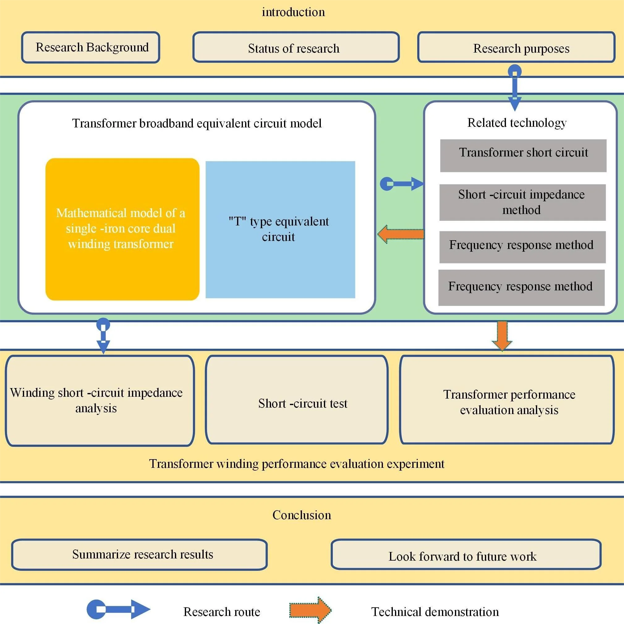
In this paper, the equivalent model of the transformer is established. By analyzing and calculating the distribution parameters of transformer windings, the quality evaluation of the transformer is analyzed and defined. Then the performance of the transformer is evaluated by the parameter changes of the short-circuit impedance before and after the short-circuit test obtained from a power grid company. By using the short-circuit impedance method, the short-circuit impedance values of the transformer before and after the short-circuit test are analyzed and compared and combined with the provisions of China's electric power industry standards, the value of short-circuit impedance change that can characterize the quality of transformer windings is obtained.
The main innovations of this paper are:
1) Short-circuit impedance method, rate response method and vibration wave method are used to estimate the winding performance of short-circuit orchestration.
2) Adopt an analytic hierarchy process to obtain a weight matrix of each index adopted for evaluating the quality of the transformer, and calculate a synthetic weight.
3) By calculating the comprehensive index of fuzzy evaluation, the evaluation conclusion is given according to the score set corresponding to the obtained score.
2. Related work
2.1. Transformer short circuit
When the transformer is suddenly short-circuited, the resistance of the low-voltage side of the transformer winding becomes smaller. The current becomes particularly large so that the coil is subjected to a large electrodynamic force. The coil of the transformer may undergo plastic deformation and cannot return to its original position, resulting in insulation problems, or even wire breakage due to excessive force on the coil. In addition, a large current is generally accompanied by temperature problems. In the case of high temperature, the performance of the transformer winding is reduced, and the transformer will fail due to high temperature. At present, the short-circuit test of transformers has become a very important means to test the quality of transformers, which has attracted the attention and concern of a large number of domestic and foreign experts and scholars in the power industry. However, there are few reports on the performance evaluation of transformer windings, and there are still the following problems:
(1) For the detection of the hanging cover, although some problems on the surface of the winding can be observed with the naked eye, it is difficult to observe the internal situation of the transformer winding through vision, and it is subjective to observe with the naked eye. Because the detection of the hanging cover will also be affected by some uncontrollable factors due to the contact of the transformer winding with the external environment [12].
(2) It is impossible to describe the winding performance state objectively, accurately, and quantitatively. And how to extract the characteristic signals of transformer windings in a lossless, fast and effective way to evaluate the performance of transformer windings [13].
(3) What kind of indicators are needed for field operators to judge the performance of transformer windings [14].
2.2. Short circuit impedance method
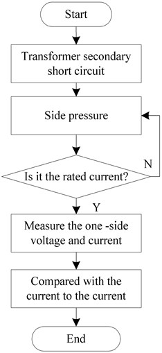
Short-circuit impedance method is the earliest method to judge whether there is deformation in the winding without hanging the cover. Compared with previous methods, this method has high repeatability and simple operation. Thus, that method is widely used, and there are many standards for this method at present [15]. The operation of this method is shown in Fig. 1.
It is closely related to the internal conditions of the transformer. If the transformer is deformed, the structure of the transformer will change accordingly, and the value of its short-circuit impedance may also change [16]. The main judgment methods are shown in Table 1.
Table 1Relationship between short-circuit impedance value and transformer state
Change of short circuit impedance | Transformer winding condition |
No changing | Non-shape-transformation |
Small changes | Slight deformation |
Big changes | Large deformation |
Fig. 1Operation flow of short-circuit impedance method
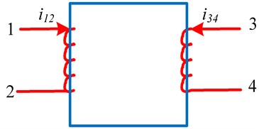
The wiring mode of short-circuit impedance method is shown in Fig. 2.
In Fig. 2, the parameters are shown in Table 2.
Fig. 2Wiring diagram of short circuit impedance method
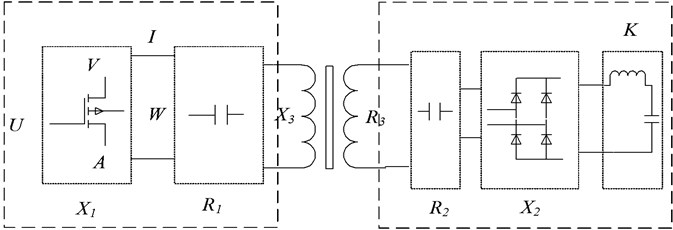
Table 2Definition of wiring parameters of short-circuit impedance method
Symbols | Definition |
Input voltage | |
Input current | |
Active power input | |
Input winding resistance | |
Input winding reactance | |
The output is equivalent to the resistance of the input | |
Output reactance equivalent to input reactance | |
Winding excitation resistance | |
Winding excitation reactance |
The calculation formula of this method is shown in Eq. (1):
2.3. Frequency response method
The frequency response method was first proposed by E. P. Dick and his colleagues. Due to the continuous research and innovation, the frequency response method has been regarded as a very mature technology, and the frequency response method can be used to evaluate transformer windings. In the case of high frequency (2000 Hz and above), the iron core of the transformer is saturated, which makes its function invalid. The winding of the transformer is regarded as a two-port network composed of RLC. When the winding structure of the transformer changes, its equivalent passive two-port network will also change, which will change the spectrum of the frequency response. By analyzing the characteristics of this change, the performance of the transformer winding can be evaluated.
The state of the transformer can be judged by both horizontal and vertical comparison methods. The horizontal comparison method is to compare the frequency response of phase A, phase B and phase C under the same conditions in the same time period, while the vertical comparison method is to compare the frequency response of phase A, phase B and phase C in different time dimensions. The longitudinal comparison method is to compare the frequency response in different time dimensions and in the same phase sequence.
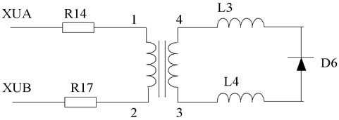
The output of FRA needs to be measured. After Laplace transform of the two functions, they can be compared with each other to obtain the function of frequency response. Through the method of horizontal comparison or vertical comparison, the performance of the winding can be evaluated. Fig. 3 shows the frequency response method detection circuit and the distributed parameter model of the transformer winding.
Fig. 3Frequency response method detection circuit and transformer winding distributed parameter model
2.4. Vibration wave law
In the oscillatory wave method, the transformer is regarded as a two-port network composed of RLC. The RLC series circuit is composed of the inter-cake capacitance, inter-turn capacitance, inductance and other distribution parameters inside the transformer. A DC source is applied to the outside. When the switch is instantaneously grounded, the system composed of the transformer constitutes the RLC oscillation circuit. Under certain conditions, the oscillation wave circuit is formed. When the internal structure of the transformer changes, the corresponding parameters such as the inter-cake inductance, the inter-cake capacitance, the inter-turn capacitance and the capacitance to ground will change accordingly. By extracting the oscillation wave index, the corresponding relationship between the index and the internal parameters of the system can be established. The performance evaluation of the transformer can be realized under the condition of not suspending the cover. The method can adopt higher voltage, can excite the characteristics of the transformer with larger energy under the condition of high voltage, and has strong capability of resisting field environment interference and good reliability.
2.5. Comparison and analysis of transformer winding evaluation methods
This paper lists several methods for evaluating the winding of a transformer, each of which has a different response to different parameters of the transformer. For slight deformation, moderate deformation, severe deformation, short circuit fault and open circuit of the winding, different methods have different response and sensitivity to the winding fault. The advantages and disadvantages of these methods are shown in Table 3.
Table 3Comparison of transformer winding deformation detection methods
Inspection method | Advantages | Disadvantages |
Short circuit impedance method | The experimental method is simple and easy to operate, and has quantitative criterion. | Difficult to reach rated current; low sensitivity; difficulty in measuring slight deformation |
Vibration method | It has strong anti-electromagnetic interference capability and is a mechanical method rather than an electrical method, so it will not add new fault points. | It is vulnerable to the interference of manufacturing level, test location, operation status, environment, etc. The technology is not mature enough, which has an impact on equipment and human safety. |
Oscillatory wave method | Strong anti-interference ability, high sensitivity and high voltage , can excite system characteristics. | Difficulty in measuring slight deformation |
In this paper, the short-circuit impedance method is mainly used, and the oscillatory wave method is supplemented. The mechanism of this method is deeply studied and the appropriate indicators are found. These methods are used to evaluate the performance of distribution transformer windings after short-circuit test.
3. Broadband equivalent circuit model of transformer
When establishing the equivalent model of transformer winding under different frequencies, the role of transformer core and winding must be considered. The transformer winding model behaves differently at different frequencies. At low frequencies, the role of the core is relatively large, including the magnetizing inductance and the resulting parasitic capacitance and core losses [17]. When the frequency increases slowly, the winding is more important, including distributed capacitance, distributed inductance, equivalent resistance, and other parameters. In the case of input voltage of 2000 Hz and above, the transformer winding can be approximately equivalent to a passive two-port network composed of RLC. At this time, the iron core of the transformer plays a smaller role and the winding plays a larger role [18]. In this paper, the short circuit impedance method, the frequency response method, and the oscillatory wave method are used to evaluate the performance of transformer windings in the frequency range of 0-10 MHz. According to the national standard, 0-2000 Hz is divided into low frequencies. 2000 Hz-20 kHz is the intermediate frequency and 20 kHz-10 MHz is the high frequency.
Table 4 shows the influence factors of frequency response at different frequencies. In the low-frequency area (within 2 kHz), the frequency response characteristics are determined by the core excitation inductance and the transformer body capacitance; in the intermediate frequency area (2 kHz-20 kHz), the frequency response characteristics are mainly affected by the coupling between windings, which is closely related to the winding layout and connection mode. In the high-frequency region (20 kHz-10 MHz), the response characteristics depend on the winding leakage inductance and the winding series capacitance to ground capacitance. In this region, the series capacitance is the decisive factor affecting the shape of the frequency response curve.
Table 4Frequency response influencing factors at different frequencies
Frequency | Frequency range | Influence factors of frequency response characteristic |
Low frequency | 0-2 kHz | Core excitation inductance and transformer body capacitance |
Intermediate frequency | 2 kHz-20 kHz | Coupling condition between windings, winding arrangement and connection mode |
High frequency | 20 kHz-10 MHz | Winding leakage inductance and winding series capacitance to ground capacitance |
To evaluate the performance of transformer windings, such as the sweep frequency method and oscillatory wave method, the transient state of transformer windings should be considered. For transient analysis, it is a simple and effective method to obtain a black-box model based on terminal measurements. In this method, the equivalent RLC circuit network is measured by terminal measurement in the factory or field, and the measured characteristics, such as impedance or admittance curve in the frequency domain, can be clearly expressed by a model accurately established by vector fitting technology [19].
3.1. Mathematical model of single-core double-winding transformer
At low frequencies (typically 2000 Hz and below), the transformer winding must be modeled to account for the core. The behavior of the core (magnetizing inductance, core power losses, and parasitic capacitances coupled to the magnetizing inductance) is significant at very low frequencies, while the effects of the windings (copper losses, leakage inductance, and other stray capacitances) are negligible [20]. In the case of low frequency, it is necessary to consider the role of the iron core. The mathematical model of the transformer is analyzed and calculated through the transformer with a single iron core and double windings, as shown in Fig. 4.
Fig. 4Transformer model with single core and double winding
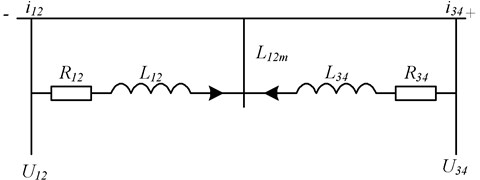
(1) Voltage equation (primary side):
(2) Flux equation (primary side):
is the self-inductance of winding 12. is the self-inductance of winding 34, and is the mutual inductance between windings 12 and 34. These three inductances need further representation [21].
is the self-inductance of 12 windings:
is 34 winding self-induction:
is mutual inductance between windings 12 and 34:
Substitute , , and in terms of permeance and coil turns into the flux linkage equation:
3) According to Faraday’s law of electromagnetic induction, the voltage and flux linkage equations are established simultaneously:
4) Winding conversion (coordinate transformation).
3.2. T-type equivalent circuit
Converted to the winding, the two ends of the voltage equation of the winding are multiplied by , which is converted to 12 windings, and the two ends of the second equation of Eq. (11) are multiplied by , which is:
The system of simultaneous equations is then transformed into:
Fig. 5 shows the "T" equivalent circuit of the transformer, which is the most basic and simplest circuit model for the analysis of single-phase transformers [22].
4. Transformer winding performance evaluation experiment
4.1. Experimental environment
When the transformer is manufactured, the characteristics and parameters of the transformer have been fixed. Thus, if the transformer is deformed, its inherent characteristics or inherent parameters may also change. In view of this situation, this paper uses the short-circuit impedance method to simulate the deformation of the winding by changing the distribution parameters in different parts of the transformer winding.
The Multisim is powerful. It can simulate the circuit, use the industrial standard SPICE simulator to simulate the circuit, which contains professional advanced SPICE analysis and virtual instruments, and can quickly verify the circuit design in advance in the design process. Thus, this paper uses the Multisim as the simulation software.
Fig. 5“T” type equivalent circuit model of transformer
4.2. Analysis of short-circuit impedance of distribution transformer winding
Because the power frequency of the short-circuit impedance method is 50 HZ, which belongs to low frequency, the transformer model adopts the “T” equivalent circuit model, which can well reflect the model of the short-circuit impedance parameters of the transformer.
For transformers with tap switches, if not specified, it generally refers to the main tap. The fractional value for the short circuit impedance is expressed as:
where: is the short circuit reactance; is the short circuit impedance; is the reference impedance; is the imaginary part of . Where is expressed as:
where, is the voltage of and winding (kV); is the reference value of rated capacity (kVA).
For the power transformer windings, as long as one of the windings is deformed, the inductance of the phase will change, so that , and will also change. Therefore, the values of , and are measured. If they change, it is inferred that the winding is deformed. The power transformers used in this paper are all distribution transformers, and their winding connection type is Dyn11. Therefore, for the connection type of the winding, the connection mode of the distribution transformer short-circuit impedance method is shown in Table 5.
Table 5Wiring diagram of transformer impedance short circuit method for Dyn11 winding connection type
Connection type | Phase sequence | Excitation test phase | Response test phase | Secondary side short circuit |
Dyn11 | A | A | B | 0-a short circuit |
B | B | C | 0-b short circuit | |
C | C | A | 0-c short circuit |
4.3. Comparison and analysis of short-circuit impedance of distribution transformer before and after short-circuit test
The current data of short-circuit impedance and transformer winding deformation of distribution transformer are the test data of short-circuit impedance before and after the short-circuit test of distribution transformer provided by several power supply companies. The data is shown in Table 6.
According to the short-circuit impedance test data before and after the short-circuit test of the distribution transformer, the relationship between the impedance change and the winding deformation can be inferred, so that the evaluation of the transformer winding can be realized.
Table 6Comparison of short circuit impedance and analysis of deformation of distribution transformer before and after short circuit test
High/low pressure (kV) | Capacity (kVA) | Phase sequence | Normal value of reactance (0) | Reactance value after test (0) | Rate of reactance change (%) | |
10/0, 4 | 630 | A | 7, 15 | 6, 55 | –8, 4 | Deformation |
B | 8, 05 | 7, 65 | –5 | Deformation | ||
C | 7, 95 | 7, 45 | –6, 3 | Deformation | ||
10/0, 4 | 315 | A | 11, 45 | 12, 225 | 33 | Serious deformation |
B | 12, 15 | 17, 625 | 45 | Serious deformation | ||
C | 12, 05 | 11, 775 | –2 | No deformation | ||
4.4. Analysis of transformer performance evaluation based on short-circuit impedance method
The capacity of the distribution transformer is generally 1000 kVA and below, and the voltage is 10 kV. If it is a longitudinal comparison, the relative change of the winding parameters of the distribution transformer will not be more than ±2.0 %. If it is a horizontal comparison, the maximum relative change of the three-phase winding parameters of the transformer should not be more than 2.5 %. For 10 kV distribution transformer, the reference value of system impedance is 0.21 Ω, as shown in Table 7.
Table 7Attention value of aspect ratio of short-circuit impedance method
Comparison | Transformer evaluation index | Capacity | Voltage | Relative variation ratio of winding parameters |
Longitudinal comparison | Short circuit impedance | 100 MAV and below | Below 220 kV | ≤ ±2 % |
Short circuit impedance | 100 MVA and above | 220 kV and above | ≤ ±1.5 % | |
Horizontal comparison | Short circuit impedance | 100 MVA and below | Below 220 kV | ≤ ±2.2 % |
Short circuit impedance | 100 MVA and above | 220 kV and above | ≤ ±1.9 % |
According to the obtained short-circuit impedance test data of the distribution transformer before and after the short-circuit test, the corresponding relationship between the short-circuit change and the deformation of the transformer before and after the short-circuit test can be obtained. Whether the test is qualified or not can be obtained to realize the performance evaluation of the transformer winding, as shown in Table 8.
For the above deformation conditions, the law of the change rate of the short-circuit reactance of the transformer and the degree of deformation is obtained, as shown in Fig. 6.
Table 8Comparison and analysis of short circuit impedance of distribution transformer before and after short circuit test
Rate of reactance change (%) | Deformation degree | Test qualification |
–8.4 | Deformation | Poor |
–5 | Deformation | Poor |
–6.3 | Deformation | Poor |
33 | Serious deformation | Very poor |
45 | Serious deformation | Very poor |
–2 | No deformation | Medium |
0 | No deformation | Excellent |
4.5 | Slight deformation | Poor |
0.42 | No deformation | Excellent |
1.5 | Deformation | Slight poor |
Fig. 6The relationship between the change rate of short-circuit impedance of transformer winding and the degree of deformation
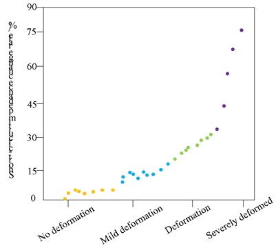
As shown in Fig. 5, after the transformer passes the short-circuit test, in the short-circuit impedance method, the change rate of the short-circuit impedance reflects the deformation of the distribution transformer. Therefore, in most cases, the short-circuit impedance method can be used to evaluate the performance of the transformer. However, since the cases of no deformation and slight deformation overlap each other, it is difficult to judge whether deformation occurs in the overlapping part. According to the Chinese power industry standard DL/T1093-2018 [23] and the horizontal comparison method [24], the following conclusions are obtained in this paper, as shown in Table 9.
Table 9Short-circuit impedance change rate thresholds for distribution transformer winding quality conditions
Excellent | Good | Medium | Poor | Relatively poor | Very poor | |
Change rate of short-circuit impedance (%) | 0 | 0-0.5 | 0.5-2.5 | 1-5 | 5-15 | More than 15 |
After a distribution transformer is subjected to a short-circuit test, the performance of a transformer winding is evaluated by adopting short-circuit impedance. A short-circuit impedance change rate threshold of the quality condition of the distribution transformer winding is obtained. When the short-circuit impedance change rate is 0, the distribution transformer is excellent; when the short-circuit impedance change ratio is 0 to 0.5 %, the distribution transformer is good; and when the short-circuited impedance change ratio is 0.5 to 2.5 %. When the change rate of short-circuit impedance is 1 %-5 %, it is poor; when the change rate of short-circuit impedance is 5 %-15 %, it is relatively poor; when the rate of change of short-circuit impedance reaches 15 % or more, it is very poor.
5. Conclusions
In this paper, an evaluation method for the performance of transformer windings under short-circuit test is proposed. By simplifying the distributed parameter model of transformer windings, a simplified equivalent model of transformer windings is obtained. The main work includes:
1) The method first studies the broadband equivalent circuit model of the transformer winding, and obtains the distributed parameters of the high-frequency equivalent model of the transformer.
2) Obtain the threshold of short-circuit impedance change that can characterize the quality of transformer windings by using the short-circuit impedance method and combining the provisions of China’s power industry standards.
3) Through the simulation, the change of the internal parameters of the transformer and the change of the indicators of the three methods are quantitatively obtained, which solves the problem of quantitative evaluation of the transformer winding performance after the short circuit test. This method does not need to hang the cover for inspection, and can effectively obtain the performance indicators of the transformer winding.
In this paper, after the short-circuit test of the transformer, the comprehensive evaluation of the transformer winding performance is carried out by a single method, which has the problems of single means and inaccurate evaluation accuracy. A comprehensive assessment of transformer winding performance considering multiple methods has not been found. In the next step, we will consider a variety of methods to evaluate the winding resistance performance of the transformer.
References
-
M. Ostrenko and B. Andriienko, “Transformer impulse surges calculation by FEM coupled to circuit,” IEEE Transactions on Magnetics, Vol. 53, No. 6, pp. 1–4, Jun. 2017, https://doi.org/10.1109/tmag.2017.2661402
-
A. Sinha and S. Kaur, “Analysis of short circuit electromagnetic forces in transformer with asymmetrically placed windings using Finite Element Method,” in 2016 Second International Innovative Applications of Computational Intelligence on Power, Energy and Controls with their Impact on Humanity (CIPECH), pp. 101–105, Nov. 2016, https://doi.org/10.1109/cipech.2016.7918746
-
G. B. Kumbhar and S. Mahajan, “The effect of distribution of a primary winding on the short-circuit forces of a current transformer,” in 2017 International Conference on Green Energy and Applications (ICGEA), pp. 153–157, Mar. 2017, https://doi.org/10.1109/icgea.2017.7925474
-
V. M. Jimenez-Mondragon, R. Escarela-Perez, E. Melgoza, M. A. Arjona, and J. C. Olivares-Galvan, “Quasi-3-D finite-element modeling of a power transformer,” IEEE Transactions on Magnetics, Vol. 53, No. 6, pp. 1–4, Jun. 2017, https://doi.org/10.1109/tmag.2017.2659662
-
K. H. Park, H. M. Ahn, and S. C. Hahn, “Astudy on calculation of short-circuit electromagnetic force in power transformer considering winding tap condition,” Transactions of the Korean Institute of Electrical Engineers, Vol. 68, No. 5, pp. 625–633, 2019, https://doi.org/10.1109/kiee.2018.068543
-
J. Jiang, L. Zhou, S. Gao, W. Li, and D. Wang, “Frequency response features of axial displacement winding faults in autotransformers with split windings,” IEEE Transactions on Power Delivery, Vol. 33, No. 4, pp. 1699–1706, Aug. 2018, https://doi.org/10.1109/tpwrd.2017.2761884
-
L. Zhou et al., “FRA modelling for diagnosing axial displacement of windings in traction transformers,” IET Electric Power Applications, Vol. 13, No. 12, pp. 2121–2127, Dec. 2019, https://doi.org/10.1049/iet-epa.2019.0362
-
J. Zhang, C. Fu, and S. Ying, “Analyze the power distribution transformer-resistant short circuit ability and quality control measures based on material random inspection results,” Transformer, Vol. 55, No. 12, pp. 39–44, 2018, https://doi.org/10.1109/tf.2017.0572
-
M. L. Yu, Z. Z. Cao, and J. X. Dong, “Long-circular power distribution transformer resisting short circuit structure and process,” Transformer, Vol. 55, No. 10, pp. 23–25, 2018, https://doi.org/10.1109/tf.2017.0596
-
D. S. He, G. F. Ma, H. M. Luo, and Z. L. Lin, “Power distribution transformer short-circuit tolerance for school check-up calculation pre-diagnosis evaluation,” Electric and Energy Efficiency Management Technology, No. 11, pp. 46–51, 2019, https://doi.org/10.1109/eeemt.2018.046071
-
C. Lai, X. Chen, X. Chen, Z. Wang, X. Wu, and S. Zhao, “A fuzzy comprehensive evaluation model for flood risk based on the combination weight of game theory,” Natural Hazards, Vol. 77, No. 2, pp. 1243–1259, Jun. 2015, https://doi.org/10.1007/s11069-015-1645-6
-
X. J. Zuo, W. X. Qian, and Y. W. Wang, “The application of the transformer resistance to short circuit capacity to analyze the model,” Power System and Its Automatic Newspaper, Vol. 30, No. 10, pp. 139–144, 2018, https://doi.org/10.1007/s11069-030-1449-8
-
G. Y. Xu, H. X. Shao, and D. M. Wang, “Highway drainage system based on Monte Carlo simulation and comprehensive weights vague comprehensive evaluation,” Journal of Chongqing Jiaotong University (Natural Science Edition), Vol. 36, No. 8, pp. 30–36, 2017, https://doi.org/10.1109/cju.2017.250796
-
B. Zhang and Y. Li, “Large-type transformers under multiple attacks for multiple attacks have been spoke to lose stability,” Journal of Electrician Technology, pp. 71–76, 2017, https://doi.org/10.1109/s111069-071-1276-1
-
T. Wang and M. S. Dong, “In the "Shenzhen – Hong Kong Stock Connect" under the Shenzhen – Hong Kong stock market, the volatile status area system conversion research – empirical analysis based on the Malcov status transition from the regression model,” Investment Research, Vol. 12, No. 38, pp. 67–79, 2018.
-
X. Z. Huang, W. Song, and Z. Y. Liu, “The exchange rate fluctuation prediction of the GARCH model based on the state of Malcov,” Statistics and Decision-Making, Vol. 6, pp. 84–87, 2017, https://doi.org/10.1080/07350015.2017.10524851
-
D. J. Li, L. Zhang, and C. H. Yu, “10KV’s influence of the transformer on the transformer of the transformer,” Guangxi Power, Vol. 2, pp. 56–57, 2019, https://doi.org/10.1109/uralcon52005.2019.9559456
-
F. X. Han, Y. Li, X. Sun, and L. Li, “Calculation of leakage magnetic field and short-circuit impedance of power transformer,” Advanced Materials Research, Vol. 3294, pp. 986–987, 2014.
-
N. Wang, W. Wang, and X. Zhang, “Transformer short-circuit impact accumulation effect assessment technology,” Electric and Electrical Appliances, Vol. 18, No. 36, pp. 44–48, 2017, https://doi.org/10.1109/eea.2017.3107799
-
S. Wang, H. Zhang, S. Wang, H. Li, and D. Yuan, “Cumulative deformation analysis for transformer winding under short-circuit fault using magnetic-structural coupling model,” IEEE Transactions on Applied Superconductivity, Vol. 26, No. 7, pp. 0–5, Oct. 2016, https://doi.org/10.1109/tasc.2016.2584984
-
Z. X. Li, L. D. Li, and S. Y. Sun, “Electric transformer short-circuit micro-shaped accumulation effect test,” Guangdong Power, Vol. 5, No. 30, pp. 92–95, 2017, https://doi.org/10.1109/gp.2017.2455369
-
D. H. Chen, Z. Li, and D. Z. Yu, “The accumulated effect analysis after multiple short circuit,” Transformer, Vol. 10, No. 55, pp. 61–63, 2018, https://doi.org/10.1109/tf.2018.1057274
-
H. J. Zhang, S. H. Wang, and S. S. Li, “Analysis of the accumulation effect of the power transformer deformation of the power transformer in many times,” Transformer, Vol. 55, No. 2, pp. 37–42, 2018, https://doi.org/10.1109/tf.2017.1059585
-
X. Zhang, L. Q. Liu, and W. Wang, “The application of the theory of coupling field in the transformer winding accumulation of deformation simulation,” Modern Industrial Economy and Informatization, Vol. 8, No. 17, pp. 20–22, 2018, https://doi.org/10.1109/miei.2018.801721
Cited by
About this article

