Abstract
The lightweight design of the electric vehicle motor brought about more serious vibration and noise problem of the motor. An accurate modal calculation was the basis for the study of the vibration and noise characteristics of the electric vehicle motor. The finite element method was used to perform the modal simulation of the PMSM. Through the reasonable simplification and equivalence of the motor stator model, the first 7 orders natural frequencies and corresponding modes of the motor stator under the free state were calculated. After that, the accuracy of the finite element model was verified by the hammering modal experiment of the prototype. Furthermore, the above results will provide the theoretical basis for the electric vehicle motor’s vibration control and NVH improvement.
1. Introduction
As a core component of electric vehicle, the research and development of the driving motor has attracted great attention at home and abroad. The Permanent Magnet Synchronous Motor (PMSM), due to its small size, high power density and high efficiency, has become the preferred driving Motor for electric vehicles. However, for automotive motors, the requirements of compact size and light weight are increasing day by day. So, the motor structure design takes light and thin as the main goal, and its stiffness is often poor, which is prone to generate large vibration and high noise, resulting in motor fatigue and seriously affecting the motor performance and reliability. Therefore, it is particularly important to study the vibration characteristics of the motor when designing the PMSM for vehicles. Modal analysis is the basis of structural dynamic analysis and vibration analysis.
There are three main methods for modal analysis of motors: analytical method and Finite Element Method (FEM) and test method. Among them, the analytical method is only applicable to the motor with simple structure. The FEM method can be used for modal calculation of irregular motor structure with high precision and wide application. However, the computational accuracy of this method depends on the accuracy of material attribute parameters and geometric parameters of the model. The modal parameters obtained by the modal test method are relatively accurate, but the cost is high because a large number of sensors need to be placed on the motor surface and more instrument channels are needed.
Many scholars at home and abroad have done a lot of research on the modal and vibration characteristics of industrial motors by finite element method and experimental modal method [1-7], but there are relatively few research literatures on the modal and vibration characteristics of electric motor [8-10].
In this paper, FEM will be used to conduct modal analysis on a driving motor of electric vehicle with a rated power of 42 kW, and the natural frequency and vibration mode of the motor will be obtained by simulation. Moreover, the modal test of the prototype will be verified by hamming method of the suspended prototype. At the same time, the improved design of stator structure is given according to the modal parameters of the motor stator.
2. Modal calculation and analysis of PMSM stator based on finite element model
The driving motor for electric vehicles studied in this paper is a forced water-cooled permanent magnet synchronous motor (PMSM), which is mainly composed of a front-end cover, a casing, a stator rotor with a copper wire and a rear end cover. The solution domain of the finite element modal simulation calculation is the stator which is one of the core components of the motor.
The motor stator geometry model is built with the UG NX10.0 software, shown in Fig. 1. Its geometry parameters are shown in Table 1. Due to the complex shape of the end windings, the influence on the number and quality of the mesh is large, but the influence on the overall stiffness of the model is small. Therefore, the actual model of the end windings is not built in the modal analysis, and the corresponding winding mass is converted into the stator slots.
Table 1The modeling geometry parameters of stator and winding
Parameters | Value | Parameters | Value |
Stator outer diameter (mm) | 204.27 | Number of stator slots | 72 |
Stator inner diameter (mm) | 109.51 | Stator tooth width (mm) | 4 |
Axial length (mm) | 114.37 | Flat copper wire size (mm) | 3×2 |
Stator yoke thickness (mm) | 14 | – | – |
The types of materials included in the stator and winding assembly are generally silicon steel, copper and resin. Considering that the stator core is formed by lamination of silicon steel sheets, the mechanical properties are different from the intact solid structure, so it is necessary to define the anisotropy of the material, shown as Table 2.
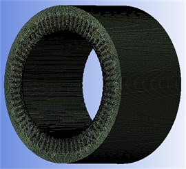
The model is meshed with the unit type Solid186. The total number of units is 833688 and the total number of nodes is 3408511. The total degree of freedom of the model is 10230000 and the FEM model is shown as Fig. 2.
Table 2Material properties of stator and its winding
Component name | Material | Density (kg/m3) | Elastic modulus (GPa) | Shear modulus (GPa) | Poisson’s ratio |
Stator core | Silicon steel (anisotropic) | 7400 | 0.9 170 | 0.2 12.5 | 0.29 |
Winding | Copper | 8900 | 0.9 90 | 1 | 0.3 |
Filling resin | Resin | 2000 | 0.6 | – | 0.3 |
Fig. 13D model of stator and its winding
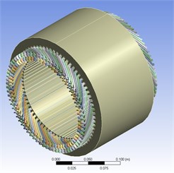
Fig. 2FEM model of stator and winding
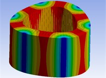
Since the motor is subjected to modal calculation in a free state, no constraint is imposed. The natural frequencies and modes of the PMSM stator are calculated by the finite element simulation software Workbench. The first seven natural frequencies and their corresponding modes are extracted from the modal calculation of the motor stator in the free state. The simulation results are shown as Table 3 and Fig. 3. The polar number of PMSM studied in this paper is 4 pairs of poles, the maximum speed is 10000 r/min, that is, the maximum operating frequency is 1333.3 Hz higher than the first natural frequency of the motor 630.7 Hz, so according to the simulation results, resonance may occur in the motor structure.
Table 3Simulation results of motor stator modal parameters
Order | Frequency / Hz | Vibration modes |
1 | 630.7 | Radial breathing vibration |
2 | 797.5 | Radial breathing vibration |
3 | 1703.6 | Radial breathing vibration |
4 | 1953.8 | Radial vibration |
5 | 2689.2 | Radial vibration |
6 | 3001.6 | Radial breathing vibration |
7 | 3333.1 | Radial local vibration |
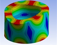
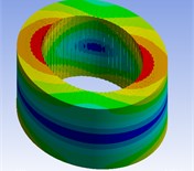
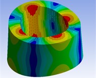
Fig. 3Simulation results of stator modes with FEM method
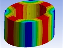
1st mode
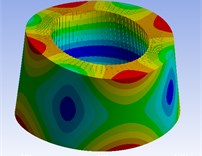
2nd mode
3rd mode
4th mode
5th mode
6th mode
3. Modal test analysis for motor stator
In order to verify the reliability of finite element modal calculation of motor, modal test analysis of motor stator was carried out.
3.1. Test procedure
3.1.1. Test platform
The motor stator, whose weight is 15.8 kg, is suspended freely by elastic rope, shown as Fig. 4. The DASP306 intelligent signal test and analysis system was used to test the vibration characteristics. The system includes digital acquisition instrument, data line, portable computer and three-way acceleration sensor, etc., which are combined with DASP software for data analysis. The motor modal test platform is shown in Fig. 4 and Fig. 5. The type of sensors is BZ1102 and its sensitivity is 0.55 PC/ms-2. The frequency response of the sensor is from 1Hz to 25 kHz and its weight is 4 g. The type of the hammer’s force sensor is BZ1202 and its sensitivity is 4.17 PC/N
3.1.2. Test points
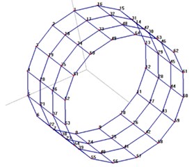
In order to extract the modal parameters of the stator accurately and obtain better modal animation, 64 measuring points are arranged on the stator according to the shape and structure of the stator. The measuring points are arranged on the outer cylinder surface of the stator. They are divided into four lines with equal spacing along the generatrix. Each line has 16 points along the circumference of the stator core. The stator coordinate system is established with the axis direction of the stator axis as the axis, the normal direction of the stator core cylindrical surface as the radial direction, and the orthogonal direction with the normal direction and the axial direction as the tangential direction. Due to the limitation of the channel number, sensors and sampling frequency of the acquisition instrument, 64 measuring points are arranged in three groups. The first and second groups have 22 measuring points respectively, and the third group has 20 measuring points. The model diagram of stator measuring points is shown as Fig. 6.
Fig. 4Stator for modal test
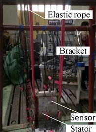
Fig. 5The measurement system
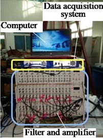
Fig. 6The measuring points of stator
3.1.3. Incentives
The hammer excitation points in three directions of (radial), (axial), and (tangential) are determined according to the coherence analysis results. Therefore, it is required that the coherence coefficient be above 0.90 in the modal test. The ρ (radial) excitation point is determined as the 10th measurement point; the (axial) excitation point is also at the 10th measurement point; (tangential) is determined as the 9th measurement point. Since the outer surface of the stator is smooth and has no protrusion, it is difficult to hammer in the tangential direction. It is necessary to install an auxiliary hammer bearing at the 9th measuring point. The auxiliary bearing is made of steel, and its weight is 38 g relative to the stator weight.
3.1.4. Test parameters
The filtering and analysis frequency was set to 6666.67 Hz and the sampling frequency was set to 17.067 kHz.
3.2. Analysis on modal test results
Compare the natural frequency simulation data with the experimental data, as shown in Table 4. It can be seen that the error between simulation and test data is between –0.30 % and 4.47 %. The experimental results are basically consistent with the simulation results, which proves that the established finite element modal simulation model of stator is practical. Furthermore, according to Table 4, the 2nd, the 4th and 6th order of modal frequencies may be excited by the radial electromagnetic excitation force of motor.
Table 4Comparison of modal parameters of stator between FEM simulation and experimental result
Order | Modal frequency / Hz | Radial exciting force of the motor | |||
Experimental result | FEM simulation | Relative error | Order of harmonics | Frequency | |
1 | 632.6 | 630.7 | –0.30 % | – | – |
2 | 795.0 | 797.5 | 0.32 % | 16 | 800 Hz |
3 | 1095.5 | – | – | – | – |
4 | 1671.8 | 1703.6 | 1.90% | 32 | 1600 Hz |
5 | 1889.5 | – | – | – | – |
6 | 1986.1 | 1953.8 | –1.63 % | 40 | 2000 Hz |
7 | 2574.1 | 2689.2 | 4.47 % | – | – |
8 | 2949.2 | 3001.6 | 1.78 % | – | – |
9 | 3296.8 | 3333.1 | 1.10 % | – | – |
4. Conclusions
In order to analyze the vibration characteristics of PMSM for vehicle, the modal analysis of a motor stator with rated power of 42 kW was carried out in this paper. The main conclusions are as follows:
1) Finite element modal analysis of the motor stator was carried out, and the second, the fourth and the sixth natural frequencies of the motor stator were calculated to be 795.0 Hz, 1671.8 Hz and 1986.10 Hz. These modal frequencies may be excited by the radial electromagnetic excitation force of motor. Through the analysis of the vibration mode of the motor stator, it is judged that the radial stiffness of stator is weak. It is suggested that the radial stiffness of stator be properly strengthened.
2) The error between the natural frequency of the motor stator measured by the test and the calculated values of the simulation is –0.30 % and 4.47 %, which verifies the accuracy of the simulation.
References
-
Lu Nan-Fang, Zhang Yu, Yang Li, Li Guang-Xi Modal analysis and experiment research rotor of high-speed permanent magnet brushless motors. Machinery Design and Manufacture, Vol. 6, 2008, p. 78-81, (in Chinese).
-
Li Mo-Wang, Huang Peng-Cheng, Fang Liang Finite element simulation and experimental research of large and medium motor stator modal. Hunan Agricultural Machinery, Vol. 41, Issue 5, 2014, p. 35-37, (in Chinese).
-
Wang C., Lai J. C. S. Vibration analysis of an induction motor. Journal of Sound and Vibration, Vol. 224, Issue 4, 1999, p. 733-756.
-
Zhang Juntang, Avoki M., Omekanda, et al. Young’s modulus for laminated machine structures with particular reference to switched reluctance motor vibrations. IEEE Transaction on Industry Application, Vol. 40, Issue 3, 2004, p. 748-755.
-
Long S. A., Zhu Z. Q., Howe D. Vibration behavior of stators of switched reluctance motors. IEE Proceedings on Electrical Power Application, Vol. 148, Issue 3, 2001, p. 257-264.
-
Chen Xiaoguang, Qu Tiejun Modal test on the model of a foundation for 1000 MW turbo-unit. Journal of North China University of Technology, Vol. 29, Issue 5, 2017, p. 129-134, (in Chinese).
-
Wang Tianqi, Wang Fengxiang Stator vibration and modal analysis of large asynchronous motor. Journal of China Electrical Engineering, Vol. 27, Issue 12, 2007, p. 41-45, (in Chinese).
-
Xi Rongsheng, Wu Boxi Modal analysis of permanent magnet synchronous motor for electric vehicle based on finite element method. Motor and control applications, Vol. 45, Issue 9, 2018, p. 108-111+131, (in Chinese).
-
Duan Min, Hao Liang, Li Weimin, Cao Jingsheng Modal analysis and experiment research of generator for vehicles. Micro Motor, Vol. 44, Issue 9, 2016, p. 23-27, (in Chinese).
-
Deng Wenzhe, Zuo Shuguang, Sun Han, Wu Shuanglong, Zhang Guohui Modal analysis Modal analysis of a claw-pole alternator considering orthotropy of the stator core and windings. Journal of Vibration and Shock, Vol. 36, Issue 12, 2017, p. 43-49, (in Chinese).
Cited by
About this article

The authors express their gratitude to the SAIC Industrial Foundation Fund (1729) for the financial support of the study.
