Abstract
Electric vehicles (EV) are considerably quieter than internal combustion engine (ICE) powered vehicles, because noise of ICE is eliminated. However, the interior noise of an EV usually contains significant high-frequency noise components caused by electrical motor, which can be subjectively perceived as annoying and unpleasant. This paper describes a numerical model to predict interior acoustic noise caused by electromagnetic forces in permanent magnet synchronous motor (PMSM) for electric vehicles. Firstly, the principle of the multiphysics method is to establish a complete 3Dstructural finite element model (FEM) of motor. Based on FEM, natural frequency and modal shape were calculated by modal analysis. Secondly, using an electromagnetic finite element solver, the excitation due to electromagnetic phenomena is obtained. This excitation is then projected onto the structure mesh of motor in order to calculate the dynamic response. Thirdly, radiated electromagnetic vibration acceleration on the surface of the motor is calculated with modal superposition method. Compared with experimental test results, the creditability of motor electromagnetic vibration simulation is proved. Finally, by combining with transfer path analysis (TPA) techniques, interior electromagnetic noise of electric vehicles is accurately predicted. According to contribution analysis, motor surface zones and transfer paths contributing largely to the interior motor electromagnetic noise are identified. The results play a significant guiding role in both electric vehicle and permanent magnet synchronous motor for noise control and analysis.
1. Introduction
Currently electric vehicles (EV) are attractive because they emit no pollutants. Although electric vehicles are almost always considerably quieter than those powered by internal combustion engines (ICE), the interior noise is characterized by high-frequency noise components which can be subjectively perceived as annoying and unpleasant [1]. Compared with ICE powered vehicles, the aerodynamic noise and road noise is rising in EV. The sound quality has been changed by new component of the motor noise [2].
Noise, Vibration and Harshness (NVH) problems related to electric motor design have nothing in common with those of gasoline or diesel engines: electric whistling is a high frequency harmonic phenomenon, easily detectable due to the low background noise of a non-thermal vehicle and mainly perceived as very unpleasant by the customer [3]. This paper takes part in this process: the goal is to predict the vibro-acoustic characteristics of a motor during the design phase.
The permanent magnet synchronous motor (PMSM) is suitable for components of EV systems. Owing to its high torque density and high efficiency, the PMSM has been used as promising candidate for many industrial applications [4].
There are many electromagnetic sources affect noise and vibration of the PMSM such as cogging torque, normal force, torque ripple, etc. Even if the excitation due to electromagnetic phenomena of electric motors is well known, the link to the dynamic excitation generating vibrations and noise is not done.
This paper focuses on the airborne noise radiated by the motor. This requires the estimation of the electromagnetic forces applied to the motor, to calculate the dynamic response of the motor and its radiation. Thus, the excitation that is the origin of motor can be deduced from this approach.
The finite element method (FEM) is used to implement this calculation methodology. Electromagnetic, mechanical and acoustic phenomena must be taken into account. This type of calculation has been presented and implemented by several authors. Jean et al. used this methodology to calculate the acoustic power radiated by the automotive motor [5, 6]. Shin et al. applied this methodology to the analysis of the vibration characteristics of a permanent magnet synchronous motor (PMSM) through investigation into its electromagnetic vibration sources [7]. Sunghyuk Park et al. predicted acoustic noise due to electromagnetic forces in interior permanent magnet synchronous motor (IPMSM) for electric vehicles [8]. Abdenour Abdelli, et al. also applied this methodology to model an interior permanent magnet motor for a hybrid electric vehicle [9]. The implementation of the general simulation method has already been detailed.
Different from the others, the key point of this paper is to predict interior motor electromagnetic noise of electric vehicle by transfer path analysis. Transfer path analysis (TPA) is fairly well established for estimating and ranking individual noise or vibration contributions at a point coupled interfaces between vibration source systems receiving passive vibroacoustic systems. Once the dynamic response of the motor has been validated, the interior motor electromagnetic noise is estimated through transfer path synthesis (TPS). This method played a significant guiding role in both electric vehicle and permanent magnet synchronous motor for sound quality design and analysis.
2. Structure modal analysis
2.1. Three-dimensional structure model of motor
Three main reasons for building the 3D finite element structural model are as follows:
1) Axial modal of motor has a significant impact on motor vibration.
2) Structure of motor end cover not only enhance the quality of the motor, but also significantly increase the stiffness of the motor stator.
3) Installation method of motor has a significant impact on the modal parameters of motor structure [10].
By creating a 3D model, structure of motor end cover can be included, while taking into account the installation method of motor. Although the 3D model significantly increased the computational effort and time, it effectively improved the accuracy of motor modal computation, thus guaranteeing accurate calculation of the electromagnetic vibration and noise of motor. PMSM studied in this paper was water-cooled motor, so inlet and outlet holes were processed on the motor shell. For hoisting assembly easily, lifting lugs were welded on the motor shell. These characters had little impact on the quality and stiffness of the motor, so lifting lugs, inlet and outlet holes had been ignored when simplified model was constructed. Motor shell, front and rear end cover and junction box contain many chamfers. These characters had little effect on modal parameters of motor, so chamfers were ignored. Wire harness, ports of wire harness and some parts of motor had little impact on the quality and stiffness of the motor, they had been ignored when simplified model was constructed. Fig. 1 shows the 3D structure model of the motor, which completely includes stator, rotor, end cover, permanent magnet, bearing and junction box.
2.2. Material properties and meshing of motor components
Calculation of motor modal required the definition of material parameters for each motor component. Motor casing, front and rear end covers, water jacket and junction box were made of die-cast aluminum; bearings were made of bearing steel; permanent magnet was made of NdFeB; while stator & rotor cores and motor shafts were made of silicon sheet and solid steel, respectively. Material parameters of motor components are shown in Table 1.
Table 1The motor material parameters
Material | Density (kg/m3) | Elastic modulus (GPa) | Poisson’s ratio (-) |
Silicon sheet | 7.85×10³ | 198 | 0.28 |
Solid steel | 7.85×10³ | 209 | 0.28 |
Bearing steel | 7.81×10³ | 207 | 0.3 |
Die-cast aluminum | 2.65×10³ | 200 | 0.34 |
NdFeB | 7.50×10³ | 160 | 0.34 |
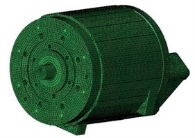
The structure model of motor was meshed, and finite element model of the motor was generated. Parts and components of motor were meshed based on their respective structural characteristics while ensuring all the mesh quality reach up to 70 %, so as to effectively control the analysis error within 10 %. Tetrahedral elements had stronger adaptability, thus general physical structures can all be divided into tetrahedral elements. Hexahedral elements, on the other hand, were often more adapted to regular physical structures. Motor casing, front and rear end covers and water jacket had relatively complex structures, so they were meshed into a total of 332,236 tetrahedral elements. In comparison, stator core, rotor core and motor shafts had relatively simple structures, which were mostly regular structures, so they were meshed into a total of 240,987 hexahedral elements. Finite element model of the motor is shown in Fig. 2.
Fig. 13D structure model of motor
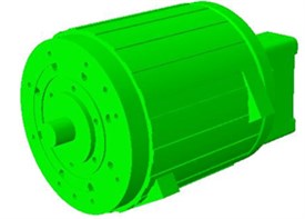
Fig. 2Finite element model of the motor
2.3. Calculation results of motor modal parameters
Front end cover of drive motor was connected to the reducer in the vehicle, while rear end cover was connected to the frame via the suspension system. Therefore, fixed constraints were applied on the motor front and rear end covers. Structural modal of motor was calculated by Block Lanczos method. To ensure the accuracy of calculation results, modal frequencies of structures were required to be at least twice the acoustic response frequency studied. Since the range of interior motor noise frequency was 0-6400 Hz in this study, the calculation range of motor modal was 0-12800 Hz.
Vibration of motor along axial direction manifest as two vibration forms: in-phase vibration and out-of-phase vibration, respectively, showed with the axial order 0 and 1. However, vibration of motor along circular direction manifest as multiple vibration forms: the elliptic vibration, the triangle vibration and quadrilateral vibration, respectively, described in circumferential order 2, circumferential order 1 and circumferential order 3 in the Shells Theory. Table 2 shows part of the calculation results of motor modal parameters. Electromagnetic noise of motors depends mainly on the radial vibration of motor structures, that is, the circumferential modal shape of motors plays a major role in electromagnetic noise. The larger the size of the motor stator is, the higher the order of modal impacting the electromagnetic noise and vibration of motors would be [11]. Motor studied in this paper was small in size. For small and medium sized motors, modal with a circumferential order less than 5 was enough to meet the requirements. Fig. 3 shows the first-order modal shape of the motor.
Table 2Modal parameter results of motor
Modes order | Natural frequency / (Hz) | Circumferential order | Axial order |
1 | 1464.7 | 2 | 0 |
2 | 1542.5 | 2 | 0 |
3 | 1647.3 | 2 | 1 |
4 | 2102.9 | 3 | 0 |
5 | 2382.9 | 3 | 0 |
6 | 2688.8 | 3 | 0 |
7 | 3104.9 | 3 | 1 |
8 | 3414.9 | 2 | 1 |
9 | 3950.2 | 3 | 1 |
10 | 4276.8 | 4 | 0 |
11 | 4928.4 | 4 | 0 |
12 | 5124.4 | 4 | 1 |
13 | 5778.7 | 5 | 1 |
14 | 5903.5 | 5 | 0 |
Fig. 3Modal shape with 1st circumferential mode
3. Motor electromagnetic forces
Electromagnetic forces causing electromagnetic vibration and noise of motor are mainly classified into the following three categories [12]:
(1) Maxwell electromagnetic force: this force acts on the surfaces of motor stators and rotors, which is the major source of electromagnetic vibration and noise of motors.
(2) Laplace force: this force acts on the motor stator coils, which can lead to vibration of the coils or possible short circuits in severe cases, thus damaging the motor stator laminations.
(3) Magnetostrictive force: after being magnetized, stator cores are susceptible to magnetostriction and thereby cause motor vibration.
At present, most of scholars who have studied the electromagnetic vibration and noise of motors generally only considered the electromagnetic forces acting on the motor stator and rotor structures, while taking no account of the latter two types of forces in general. Therefore, electromagnetic forces mentioned in this paper refer to the Maxwell electromagnetic force that acts on the motor stators and rotors.
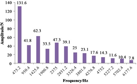
Calculations of electromagnetic fields and forces were achieved using JMAG Designer software. Fig. 4 shows the finite element analysis model of motor. 2D transient magnetic field of the motor at 3564 r/min (in this study, actual motor speed was measured to be 3564 r/min during the noise and vibration tests conducted in an anechoic room using all-electric car under 50 km/h uniform-velocity steady-state conditions) was calculated by time-stepping finite-element method. Meanwhile, electromagnetic forces on motor stator and rotor were calculated based on Maxwell’s law. Primary frequencies and amplitudes of electromagnetic forces were obtained by spectral analysis. Fig. 5 shows the frequency spectrograms of electromagnetic forces.
Primary frequencies of electromagnetic forces were the integer multiple of fundamental electromagnetic force frequency, which was the product of rotational frequency and number of rotor poles of motors [13]. In tests, rotational frequency of the motor was 59.4 Hz and the number of rotor poles was 8, hence the fundamental frequency of electromagnetic force was 475.2 Hz. Electromagnetic noise frequency was closely related to these frequencies.
Fig. 4Finite element analysis model of motor
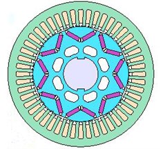
Fig. 5The frequency spectrograms of electromagnetic forces
4. Electromagnetic vibration response of motor
The calculation methodology assumes a weak coupling between the different physical levels. As the calculation of electromagnetic forces and the establishment of a complete 3D finite element model of motor structure have been completed earlier, the electromagnetic forces were simply needed to apply to the motor stator and rotor, and then the electromagnetic vibration accelerations at the motor surface are calculated using LMS Virtual.Lab software [14].
Vibration response of the motor structure was calculated by modal superposition [15]. The modal superposition method requires the determination of damping ratio corresponding to each vibration modal order. In case of a structural resonance, there will be considerable vibration, whose amplitude may reach infinity if structural damping is not considered. Damping ratio can be obtained through tests, but such tests were difficult and costly. In this paper, linear damping ratio was used as shown in Eq. (1):
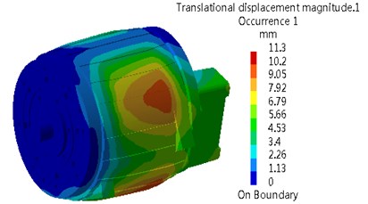
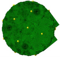
where: was the modal natural frequency; and was the damping ratio corresponding to the natural frequency. Fig. 6 shows the contours of electromagnetic vibration acceleration of the motor at a certain frequency.
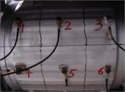
During the noise and vibration tests of electric car on revolving drum test table in the anechoic room, the motor surface was divided into 32 equal-area zones numbered 1-32. Acceleration sensors were arranged in the center of each zone for measurement of vibration accelerations at the motor surface. Fig. 7 shows the locations of the acceleration sensors.
Fig. 6Contours of motor electromagnetic vibration acceleration
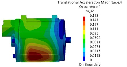
Fig. 7Measurement point arrangement in the test
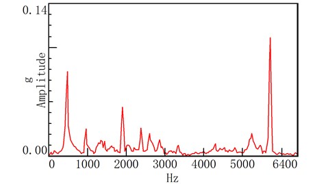
Since the electromagnetic vibration accelerations at the motor surface have been calculated, the corresponding electromagnetic vibration accelerations can be obtained simply by inserting measuring points on the surface meshes of the motor. As shown in Fig. 8, the peaks of motor surface vibration accelerations at frequencies of 475.2 Hz, 950.4 Hz, 1900.8 Hz, 2851.2 Hz, 5227.2 Hz and 5702.4 Hz were caused apparently by the motor electromagnetic forces. (Motor electromagnetic force frequency) was an integer multiple of the product of (number of rotor poles) and (rotational frequency), i.e. The number of rotor poles of permanent-magnet synchronous motor studied herein was 8, while the motor rotational frequency was 59.4 Hz under study conditions. Such peak frequency was entirely consistent with the motor electromagnetic frequency. Meanwhile, vibration acceleration peak was caused by the electromagnetic vibration of motor.
Fig. 8Vibration acceleration simulation results compared with the experimental results
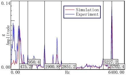
As shown in Fig. 8, it was found by comparison between simulation and experimental results of vibration accelerations at point 1 of motor surface that the experimental vibration acceleration had many peaks, which were greater than the simulated vibration acceleration as well. This was because the electromagnetic vibration studied herein was only that of motor under the action of electromagnetic force, while motor vibration may also be caused by rotor dynamic imbalance, air flow disturbance, etc. Additionally, the test was carried out under full-vehicle conditions, so the vibration acceleration at motor surface was also affected by other vehicle parts.
5. Prediction of interior motor electromagnetic noise
5.1. Principle of transfer path analysis
Electrical motors for electric car, as the noise source, have large volume and wide, dispersed sound field distribution, which cannot be seen as a single point noise source during prediction of interior electromagnetic noise of motors. Instead, motor surface should be divided into multiple small zones, with each small zone being regarded as a point noise source. Air transfer path from each point noise source to the interior target point differed [16]. Therefore, interior motor electromagnetic noise was synthesized based on the principle of transfer path analysis.
Supposed that electric car was linear time-invariant, then we can know from the linear superposition principle that the sound pressure at the interior target point was superposed by various noise sources transferred to the interior by air transfer via different paths, as shown in Eq. (2):
where denoted the noise at the interior target point; denoted the airborne noise of th noise source; denoted the noise source excitation of th airborne noise; and was the air transfer function from th noise source to the interior target point.
Noise source excitation and air transfer function were the two basic conditions for synthesis of interior electromagnetic noise of motors. Motor electromagnetic noise radiates into the air through the motor surface, and is then transferred to the interior through body panels, window glass and cavities. In this paper, motor surface was divided into 32 equal-area zones, where each zone was equivalent to a point noise source and had their own air transfer path. Thus, the noise at the interior target point can be expressed as:
In the following, air transfer function for these 32 transfer paths was measured and exciting force was calculated.
5.2. Measurement of air transfer function and calculation of noise source excitation
Based on Eq. (3), air transfer function can be expressed as:
Because of the tight space constraints, microphones may be hardly arranged in engineering application, and so the reciprocity method is usually adopted to carry out air transfer function measurement. If the system is linear is time-invariant and passive and transfer characteristics do not change while excitation location and response location can be interchangeable, this system is reciprocal. In other words, reciprocity for the same transfer path is that the transfer function is unchanged by the change of measuring direction. The reciprocity method is effective for acoustic system and mechatronics engineering.
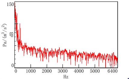
Air transfer function from motor surface to interior target point was measured through test. The test was conducted in an anechoic room. Site near the right ear of driver was selected as the interior target point, as shown in Fig. 9. During the test, microphones were arranged above the center of each zone 10 mm from the motor surface, as shown in Fig. 10, so as to minimize the noise interference coupling between transfer paths. LMS medium-high frequency volume velocity source was arranged on noise source and emitted the white noise. Based on Eq. (4), each air transfer function could be calculated. Fig. 11 shows the air transfer function from motor noise source 1 to the interior target point.
Fig. 9Target in the car
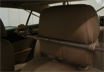
Fig. 10Sensor arrangement of Motor noise points
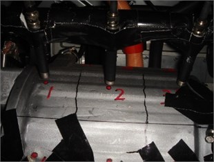
Fig. 11The air transfer function from motor noise source 1 to the interior target point
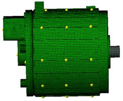
After calculation of the transfer function, the excitations of motor surface need to be obtained. Based on the location of each zonal center on the motor surface, electromagnetic vibration acceleration of each point was extracted on the motor surface meshes as the noise source excitation using Noise & Vibration module of LMS Virtual.Lab software, as shown in Fig. 12. Fig. 13 shows the electromagnetic vibration acceleration of noise source 1 on the motor surface.
Fig. 12Excitation position of the motor surface
5.3. Synthesis of interior motor electromagnetic noise
The estimated transfer function of each path obtained through experiment and the vibration acceleration of each noise source at motor surface obtained by simulation were introduced into the TPA module of LMS Test.Lab software to create hybrid test model for synthesis of each transfer path noise and calculation of interior motor electromagnetic noise.
Fig. 13Motor surface vibration acceleration of noise point 1
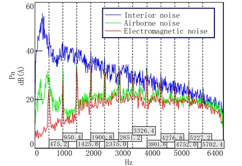
In this paper, noise at the interior target point was measured during the test of electric car on revolving drum test table in the anechoic room under 50 km/h uniform-velocity steady-state conditions, and motor airborne noise at the target point was obtained by experimental method [17]. Fig. 14 shows the comparison between experimental and simulated noise. Measured interior noise was the superimposed noise of each noise source at the interior target point, including powertrain noise, tire noise, suspension structure noise, etc. Motor airborne noise was generated at the interior target point by vibration radiated noise at the motor surface through air transfer path. Such noise was radiated by motor vibration caused by motor suspension force, rotor unbalance force and electromagnetic force, where the noise caused by motor suspension force and rotor unbalance force was mainly middle and low frequency noise and the electromagnetic noise caused by motor electromagnetic force was high frequency noise. As can be seen, the interior motor electromagnetic noise was in good agreement with the airborne noise at high frequency, which was particularly in excellent agreement with the measured interior noise at the main frequency. It can also be seen that the motor electromagnetic noise contributed largely to the interior high frequency noise, and that the electromagnetic noise had a significant impact on the interior acoustic environment.
Fig. 14The comparison between experimental and simulated noise
5.4. Contribution analysis
Interior motor electromagnetic noise was formed by each noise source at the motor surface, which was gradually attenuated via respective air transfer path and finally superimposed at the interior target point. That is, interior motor electromagnetic noise was subjected to the combined effects of excitation source and transfer characteristics. Fig. 15 shows the contribution of each transfer path to the interior motor electromagnetic noise. As can be seen from the figure, noise contributions at motor surface zones 14, 17, 20, 22, 23 and 32 all exceeded 25 dB(A). This means that these zones or transfer paths contributed largely to the interior motor electromagnetic noise, which were the primary contribution paths for interior motor electromagnetic noise. These zones were distributed mainly on the upper motor surface and motor junction box, as shown in Fig. 16. Thus, it can be seen that the upper motor surface and motor junction box were the primary parts contributing to the interior motor electromagnetic noise.
Fig. 15Contribution of each transfer path to motor electromagnetic noise
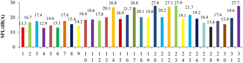
Motor surface zones and transfer paths contributing largely to the interior motor electromagnetic noise are identified by contribution analysis. Measures, such as reduction of vibration by sticking damping material to the motor surface zones with severe vibration or reduction of air transfer function by filling sound-absorbing material at the vehicle cavities, can be taken to reduce the interior motor electromagnetic noise, which provides guidance for the attenuation of interior high-frequency noise.
Fig. 16The larger area of motor electromagnetic noise contribution
6. Conclusions
A methodology for predicting interior motor electromagnetic noise has been developed. The principle of the multiphysics method is to establish a complete 3DstructuralFEM of motor. Based on FEM, natural frequency and modal shape are calculated by modal analysis. Using an electromagnetic finite element solver, the excitation due to electromagnetic phenomena is obtained. Electromagnetic excitation is then projected onto the structure mesh of motor in order to calculate the dynamic response. Radiated Electromagnetic vibration acceleration on the surface of the motor is calculated with modal superposition method. Compared with experimental test results, the creditability of motor electromagnetic vibration simulation is proved. Noise source excitation is calculated by modeling and simulation, while transfer function from motor surface to interior target point is obtained through test. A hybrid test model is created based on the principle of transfer path analysis by combining simulation results with test data for prediction of interior motor electromagnetic noise. Combining with TPA technique, the interior electromagnetic noise of electric vehicles is accurately predicted. The interior motor electromagnetic noise is in good agreement with the airborne noise at high frequency, which is particularly in excellent agreement with the measured interior noise at the main frequency. It can also be seen that the motor electromagnetic noise contributed largely to the interior high frequency noise, and that the electromagnetic noise had a significant impact on the interior acoustic environment. It is further confirmed that the motor electromagnetic noise is a significant component of interior high-frequency noise. Using contribution analysis, it can be seen that the upper motor surface and motor junction box were the primary parts contributing to the interior motor electromagnetic noise. Measures can be taken to reduce the interior motor electromagnetic noise, which provides guidance for the attenuation of interior high-frequency noise. This method plays a significant guiding role in both electric vehicle and permanent magnet synchronous motor for noise control and analysis.
References
-
Govindswamy K., Eisele G. Sound character of electric vehicles. SAE Technical Paper, 2011, https://doi.org/10.4271/2011-01-1728.
-
Brandl Stephan, Graf Bernhard Sound engineering for electric and hybrid vehicles. 1st International Electric Vehicle Technology Conference, 2011.
-
Hirotaka Shiozaki, Yoshihisa Iwanaga, Hideki Ito, Hideki Ito, Yutaka Takahashi Interior noise evaluation of electric vehicle. 1st International Electric Vehicle Technology Conference, 2011.
-
Torregrossa D., Peyraut F., et al. A new passive methodology for reducing the noise in electrical machines: Impact of some parameters on the modal analysis. IEEE Transactions on Industry Applications, Vol. 46, Issue 5, 2010, p. 1899-1907.
-
Dupont Jean Baptiste, Bouvet Pascal Multiphysics modelling to simulate the noise of an automotive electric motor. SAE Technical Paper, 2012, https://doi.org/10.4271/2012-01-1520.
-
Dupont Jean Baptiste, Dupont Jean Baptiste, et al. Simulation of the airborne and structure-borne noise of electric powertrain: validation of the simulation methodology. SAE Technical Paper, 2013, https://doi.org/10.4271/2013-01-2005.
-
Shin H.-J., Choi J.-Y., et al. Vibration analysis and measurements through prediction of electromagnetic vibration sources of permanent magnet synchronous motor based on analytical magnetic field calculations. IEEE Transactions on Magnetics, Vol. 11, Issue 48, 2012, p. 4216-4219.
-
Park Sunghyuk, Kim Sungil, et al. A numerical model for predicting vibration and acoustic noise of IPMSM. IEEE 8th Conference on Vehicle Power and Propulsion, Seoul, 2012.
-
Abdelli Abdenour, Le Berr Fabrice Analytical approach to model a saturated interior permanent magnet synchronous motor for a hybrid electric vehicle. SAE Technical Papers, Vol. 4, Issue 1, 2011, p. 301-313.
-
Li Y. B., Ho S. L., Fu W. N., Xue B. F. Analysis and solution on squeak noise of small permanent-magnet dc brush motors in variable speed applications. IEEE Transactions on Magnetics, Vol. 45, Issue 10, 2009, p. 4752-4755.
-
Gieras J. F., Wang C., Lai J. C. Noise of Polyphase Electric Motors. Boca Raton, 2006.
-
Torregrossa Dimitri, Fahimi Babak Multiphysics finite-element modeling for vibration and acoustic analysis of permanent magnet synchronous machine. IEEE Transactions on Energy Conversation, Vol. 26, Issue 2, 2011, p. 490-500.
-
Zhu Z. Q., Xia Z. P., Wu L. J. Influence of slot and pole number combination on radial force and vibration modes in fractional slot pm brusless machines having single- and double-layer windings. IEEE Energy Conversion Congress and Exposition, 2009, p. 3443-3450.
-
Pellerey P., Lanfranchi V., Friedrich G. Vibratory simulation tool for an electromagnetically excited non skewed electrical motor, case of the wound rotor synchronous machine. ElECT-RI MACS2011, CergyPontoise, 2011.
-
Rainer S., Bíró O., Weilharter B. Weak coupling between electromagnetic and structural models for electrical machines. IEEE Transactions on Magnetic, Vol. 46, Issue 8, 2010, p. 2807-2810.
-
Rong Guo, Gang Wan A study on the transfer path of the interior noise of a fuel cell car. Automotive Engineering, Vol. 29, Issue 9, 2007, p. 635-641.
-
Wu Wenzhi Research on Electric Vehicle Interior Sound Quality Prediction Model Development. Jilin University, Changchun, 2014.
Cited by
About this article

This work was supported by the Science and Technology Development Project of Jilin Province of China (Grant No. 20126007).
Kun Qian wrote paper and established a complete 3D structural finite element model (FEM) of motor. Jintian Wang proposed general frame and calculated natural frequency and modal shape by modal analysis. Yang Gao calculated radiated electromagnetic vibration acceleration on the surface of the motor with modal superposition method. Qiang Sun made transfer path analysis (TPA). Jie Liang identified motor surface zones and transfer paths contributing largely to the interior motor electromagnetic noise.
