Abstract
In order to solve the problem that electromechanical coupling had influences on the control effect of multi-pile hammers linkage, the coupling influence rules were studied. With the complex system of hammer-pile-soil being simplified, the dynamic model was constructed for the two pile hammers vibration system. The mathematical equations of systemic electromechanical coupling were established. Based on the Hamilton principle, synchronous operation conditions and system stability were established. Simulation model was developed with MATLAB/Simulink for numerical simulation. The electromechanical coupling processes and the basic system rules were obtained under different electrical motors’ speeds, the initial phase differences, soil parameters and fixing parameters. It could be found that electromechanical coupling might result in self-synchronization under given conditions. Finally, the mathematical model’s validity, theoretical derivation and simulation results were proved by some experiments. The analytical conclusions of electromechanical coupling rules provide the theoretical evidence for making control strategy on electric control linkage mode, and the basis for related engineering applications and experiments.
1. Introduction
The multi-hammer vibration technology is the use of several vibratory hammers to pile together. It solves the problem that the power is not enough when a single vibratory hammer is used in large diameter pile projects. On the project of Kansai International Airport in Japan, the large steel cylinder, which was 23 m in diameter, was hammered down by eight vibratory hammers (150 kw) connected with the driving shafts in series. Another cylinder was 13.5 m in diameter and was hammered down by four hydraulic hammers connected with bevel gears in China. The following linkage mode is used in some hydraulic vibratory hammers projects currently. Tools such as axle coupling devices are used to connect with each hammer’s rotation axis and make their speeds and phases synchronous [1]. Due to the complexity of foundation load, the synchronous gears are often subjected to severe frictions and impacts during construction. Thus, the service lives of vibratory hammers are greatly shortened. These influence factors, such as high power of hydraulic hammers, violent load changes, pipeline leak, pipeline differences, etc., are seriously restricting the development of equipment performance to the high level. To solve the problem, PVE Company in Holland presented an electronic control linkage method [2]. Phase difference was detected by electricity and adjusted by computer software in real time. Multiple vibratory hammers were putted on the pile in parallel. Through the phase difference between the eccentric blocks being detected, both the speeds and phases of vibratory hammers are controlled synchronously with modern technologies to achieve the maximum energy synthesis. However, no more related project applications of the method can be found afterwards.
Because vibratory hammers are connected with each other through the vibrating objects, there are some electromechanical coupling effects [3] in the multi-hammer synchronous vibration system. The coupling problem is a complex and multidisciplinary subject. For the depth of scientific mechanism and the breadth of the involved subjects, it has become one of the hot and difficult points in current scientific researches. Both domestic scholars and foreign scholars have made detail researches on the electromechanical coupling characteristics of vibratory mechanical system. Cairo and Dente [4] analyzed the vertical harmonic vibration of pile groups combined with closed-form stiffness matrices, which was derived by Kausel and Roësset [5]. Masoumietal [6] proposed a linear coupled finite element-boundary element model to predict vibrations in the free field due to the vibration and pile driving. This model is extended to analyze the non-linear constitutive behavior between soil and piles [7]. Dr. Blekhan [8] from the former Soviet Union presented the common definition of mechanical synchronization and the basic synchronization theory of double vibrators. Czolczynski [9] investigated the synchronization of two non-identical self-excited oscillators with computer simulation. The oscillators were suspended on the elastic structure. Japanese scholars, such as Inoue and Araki, used double motors to drive the planar vibrator to achieve its thrice frequency synchronization. Chinese academicians, such as Wen Bangchun, made intensive researches of vibration and control synchronization of mechanical systems and drew many key conclusions [10]. They are mainly for the vibrators with little damping and stiffness driven by low power motor. These scholars have greatly developed vibratory synchronization theories and control synchronization theories. Those research findings have been applied in industries. Self-synchronous vibrators driven by motors have been widely used currently. However, there are few applications of self-synchronization theories applied in vibratory piling field.
When vibratory synchronization theories are applied to pile hammer groups, the transmission used to provide rigidity will be cancelled. Thus, the structure of the vibratory pile drive is simplified, the heating of system is reduced, while the reliability and production efficiency of system are improved. The research shows that the object stiffness has an important effect on the realization of self-synchronous vibration [10]. The piling objects are large diameter cylinders with the geology of large damping and stiffness used in the large projects, such as cross sea bridge construction projects. The coupling characteristics of vibratory pile hammers are different from the general synchronous vibration mechanical system. They are affected by motor characteristics, soil parameters, the installation position and the distance between pile hammers. How do they affect the synchronization of the large damping and stiffness vibratory hammer system? It needs to be further studied. The synchronous vibration mode of pile hammers can make vibration energy fully used for piling. Strong electromechanical coupling exists among multiple vibratory pile hammers. It will impact the synchronous control. From current research papers, there are few researches on the electromechanical coupling characteristics of multi vibratory pile hammers at home and abroad. Therefore, the electromechanical coupling characteristics were studied for the multi vibratory pile hammers driving system to get the basic coupling rules. It is of great importance for the further researches of synchronization control.
In this paper, the dynamic model and electromechanical coupling mathematical equations were established for the two electric driven pile hammers linkage system. The coupling mechanism was approximately analyzed. The coupling strength expression and the influencing factors were determined. Based on the Hamilton principle, the conditions for steady and synchronous operations were established. Then the electromechanical coupling process of the system was numerically simulated. The electromechanical coupling process and the basic rules were obtained under different motor rotation speeds, initial phase differences and soil parameters. At last, theoretical derivation and simulation results were validated by experiments. It provides available references and theory basses for making the synchronous control strategy of pile hammers and related engineering applications.
2. Electromechanical coupling mathematical model of vibration system
The stiffness of soil is much smaller than the one of a pile in the piling process. According to the literature [11, 12], when building system model they are reasonably assumed as follows: 1) The soil is elastomer. The hammers and piles are absolutely rigid bodies. 2) When the piles are vibrated, damping force and elastic force are linear functions of pile speed and displacement separately. 3) Two eccentric blocks’ eccentric torques are symmetrically equal. The motor drive has the same angular velocity of rotating in the opposite direction (assured by the transmission gear). The centrifugal force of the direction is compensated for each other. Exciting force is superimposed perpendicular to the direction.
Vibratory system mechanics model is displayed in Fig. 1, where is an absolute coordinate, is a moving coordinate, is included angle between two coordinates, is motion synthesis barycenter, is the barycenter of vibratory mechanism(vibratory hammer and vibratory object), is the midpoint of vibratory hammer eccentric block rotation center line. , , . is the mass of eccentric block, is the rotating angular velocity of double vibratory hammers’ eccentric blocks, is the eccentricity of the eccentric block, , , , are soil stiffness coefficients, , , , are soil damping coefficients respectively.
Fig. 1Two vibration hammers excitation system model
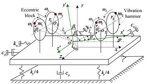
While vibrating hammers are being excited, the vibrating body will engender both vertical and deflecting vibrations. The rotary eccentric block is supposed as the object. The kinetic model is built with Lagrangian method and the kinetic equation is also developed. , , , , and are chosen as generalized coordinates. Where the vibratory system’s kinetic energy , potential energy and generalized force are shown as follows:
Mass center equation is:
Eqs. (1)-(3) are put into Lagrangian equation [12]. Eq. (4) is considered, then the kinetic equation of the vibratory system can be obtained as follows:
where is the rotary inertia of the vibratory system, is the rotary inertia of the motor, is electromagnetic torque of the motor shaft, is the total mass of vibratory hammer and pile.
The electric driven vibratory hammer uses three-phase asynchronous motor. Under the two-phase synchronous rotating coordinate, the mathematical model [13] can be expressed as follows:
where , are stator terminal voltages, , are rotor terminal voltages, , are stator terminal currents, , are rotor terminal currents, , are stator and rotor resistances separately, are self-inductances coefficients separately, is mutual inductance coefficient, , are synchronous rotating and rotor angular velocity separately. is friction and windage resistance torque coefficient, is rotary inertia of motor groups.
The electromechanical coupling mathematical model of double vibratory hammers system is composed of the kinetic equation Eq. (5) and the electrical motor mathematical models Eqs. (6), (7). From the mathematical models, it’s not an ideal system where the vibratory subsystem and the kinetic subsystem affect each other. It expresses the electromechanical coupling relationship between the kinetic subsystem and the vibratory subsystem.
3. Synchronization and stability analysis of a vibration system
The vibration system is a complete and non-conservative system. According to the Hamilton principle, the integral interval is in a vibration period. The model is:
where, is Hamiltonian function, is generalized force, is generalized coordinate.
In the established model, generalized force consists of two parts, the damping force of the vibration system and the driving torque of the motor. The two parts are the functions of the generalized coordinate . Then the expression of Hamilton principle in the model is:
where, is the Hamilton action amount in a motion cycle.
The displacement response of the system can be approximated by the displacement response at an average speed. According to the superposition principle of linear equations, the steady responses of and in the vibration system can be obtained as follows:
where, , are amplitudes in the directions of , respectively, , are phases in the directions of , respectively.
According to Fig. 1 the mechanical model of two piling hammers vibration system, the kinetic energy of the system is Eq. (1) and the potential energy is Eq. (2) under the coordinates of , , , , and . The Hamiltonian action can be obtained by substituting Eqs. (1), (2) into the Hamiltonian mathematical expression. is the kinetic energy of the mass of vibration. The kinetic energy can be taken as a constant when the motor is running steadily. The action of a steady vibrating system in one cycle is:
where, is the system (including two hammers) moment of inertia, is the total mass of pile hammer and pile.
Suppose that two hammers are symmetrically installed, and the mechanical structure and geometric dimensions are exactly the same. Set:
where , , , is the phase difference of the two motors. With the variation of generalized coordinate , the Hamiltonian function is:
Then, Eq. (12) can be changed into Eq. (13):
where:
In addition to the force, the system is impacted by the driving torque and damping torque of the motor in the motion process. Taking as the generalized coordinate, the generalized force formula of the vibration system is obtained by virtual power method.
The first part of generalized force is generated by the damping force. The generalized coordinate is changed to get:
The second part of the generalized force is driving force torque. In the motion process, the driving torque of the two motors is , and the friction torque of the motor shaft is . Taking as the generalized coordinate, the system has two free degrees. The generalized force is:
If the driving torque difference is , the resistance torque difference is , then the generalized force is:
The Eqs. (13), (14), and the Eq. (16) are substituted into Eq. (9), then:
If has a solution in the Eq. (17), the condition shall be 1, namely:
where, is synchronicity index, is the stability index in the synchronous state, , are the differences of torque and resistance respectively.
With the phase difference of two eccentric rotors being adjusted, the loading torques of two motors can be changed. Then the vibration system frequency capture can be achieved. is defined as the system frequency capture torque. The larger is, the easier the system is to get into a synchronous status. Deflection vibration is useful for synchronization. Whether the system can get the synchronous status, it depends on the ability of adjusting the capture torque of the vibration system. The more similar the parameters of the motors are, the less the electromagnetic torque difference of the motors is. The easier the synchronization conditions are to get. When 1, the adjusting ability of system frequency capture torque is less than . The system can not realize frequency capture and synchronous operations of two motors.
The conditions of a steady system were analyzed based on the function extreme, the stability of the multivariable function system and the extreme theory of the function. According to the Hamilton principle and the mathematical extreme method, the steady condition is that the extreme of the Hamilton function exists. The second variation of Hamilton action is greater than zero, 0, the steady condition can be obtained by simplifying it:
Eq. (19) is the steady synchronization condition of the two hammers vibration system. is defined as the parameter of synchronous operation stability of the system. It is closely related to stiffness, damping ratio and response state. If 0, the stable range of phase difference is . If 0, the stable range of phase difference is .
4. The numerical simulation analysis of system coupling process
With the vibration system model being built, the numerical simulation described the detail behaviors and related parameters’ influence rule and validates the accuracy of theory derivation. Based on GB50040-96 criterion and document [14], the soil parameters in the simulation were chosen as follows: The equivalent stiffness coefficients , were 2×10⁸ N/m, 1×10⁵ N/rad respectively. The equivalent damped coefficients , were 2×10⁵ N·s/m, 0.2×10⁵ N·s/rad respectively. The vibratory hammer applied the parameters of DZPJ90 type electrical driving vibratory hammer. The equivalent stiffness coefficient and equivalent damping coefficient were gradually increased with the sinking of pile, but they could be considered to be invariable in the same layer of discrete soil with a certain thickness. Therefore, it was reasonable to simulate the dynamic equation described by Eq. (5) within a short time.
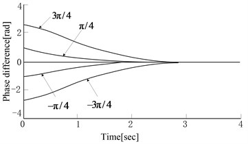
The parameters of two hammers are supposed to be the same, such as mechanical structure, physical dimension, electrical motor’s performance, etc. When the speeds of two hammers’ electrical motors are the same and the initial phase difference is , the simulation results are shown in Fig. 2. The phase difference will be converged to zero gradually. The speed of electrical motor can be converged more quickly when the speed is higher within limits. But when the speed comes up to 1500 r/min, the phase difference will tend to be a non-zero value. The result is shown in Fig. 2(c). It’s proved that the speed of electrical motor has a limit value for making phase difference converged to zero. It is closely related to soil parameters and vibration system parameters, etc. When the phase difference tends to be zero, the amplitude in the direction is also changed from the disorder status to the stable status gradually. The torsion angle will decay and tend to be zero gradually. The results are shown in Fig. 2(a) and Fig. 2(b). The results of different initial phase differences are shown in Fig. 2(d). The smaller initial phase difference is, the faster convergence rate changes. The rotation speed variation process of eccentric blocks is from an asynchronous fluctuation to a synchronous fluctuation and achieves to a fixed phase difference value at last. Based on the simulation test, it can be concluded that under certain conditions, the electromechanical coupling has the effect of making rotating speed and phase difference tend to be a fixed value. When the excitation frequency reaches to a certain value (The vibration acceleration in the direction reaches to a certain value, that is to say, the inertia load torque reaches to a certain value), phase difference will tend to . When the vibration acceleration in the direction is small, phase difference will tend to zero.
Fig. 3 shows the simulation result when the electrical motor’s speed difference is large. When the system is simulating, one electrical motor’s speed is 1000 r/min and the other is 1035 r/min. The speed difference is 35 r/min. Fig. 3 shows that the phase difference curve emanative. When the electrical motors’ speeds are the same or similar, phase difference will tend to be zero or a fixed value automatically. It results from the effects of the system electromechanical coupling, vertical vibration and deflection vibration. The simulation conclusions align with the theoretical derivation. Meanwhile, electromechanical coupling is also closely related to the exciting position and vibratory object characteristics. When the rotational speed difference is small, self-synchronization can be realized. When the rotational speed difference is large, self-synchronization can’t be realized. The large speed difference can’t meet the synchronization conditions shown in Eq. (18). Therefore, phase difference curve does not converge. The simulation results validated the correctness of the theoretical derivation in Section 3.
Fig. 2Simulation results of electromechanical coupling process
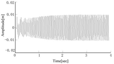
a) Amplitude variation in the direction
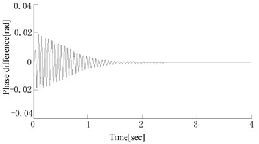
b) Torsion angle change
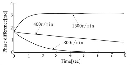
c) Phase differences of different motor speeds
d) Phase differences of different initial phases
Fig. 3Phase difference under the large motor speed difference
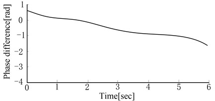
The simulation results showed that phase difference would tend to be zero or a fixed value in the ideal case when the rotation speeds of the motors were the same or similar. It was the result of electromechanical coupling in the pile hammer vibration system. The electromechanical coupling effect was transferred by the load torque of the motor. The change of vibration state led to the change of vibration acceleration. Thus, the load torque of motor was changed. The rotation speed of motor was changed, and phase difference was changed accordingly. Thus, the vibration state was changed with the combined influence of vertical vibration and deflection vibration again and again. Finally, the system tended to be stable. The rotation speed and phase difference were kept constantly, that is the phenomenon of self-synchronization.
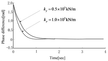
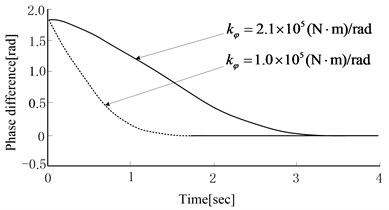
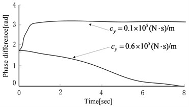
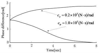
Under ideal situations, the electrical motors’ speed of two vibratory hammers was set as 1100 r/min. Based on different soil parameters, the simulation results are shown in Fig. 4. The larger was, the sooner phase difference tended to be zero. The smaller was, the sooner phase difference tended to zero. When was smaller, phase difference would tend to be a nonzero steady value. When was larger, the phase difference would converge to zero. The larger was, the faster the convergence rate changed. was opposite to for affecting system electromechanical coupling.
From the simulation analysis of equivalent stiffness and damping, and the simulation results of excited frequency, the following conclusions could be inferred. Under the over resonance region situations, the stronger the vertical vibration was (the smaller equivalent stiffness and damping in thedirection was), the easier phase difference tended to be . The stronger vibratory body torsion was (the smaller equivalent stiffness and damping in the direction was), the easier phase difference tended to be a fixed value next to zero finally. In the process of pile sinking, the equivalent stiffness and damping is increasing while the penetration depth of pile is increasing [15]. At the beginning of pile sinking, the vertical vibration and the torsion vibration were stronger, and phase difference would tend to be a nonzero fixed value. When the pile was sinking, the torsion vibration was smaller and smaller, and the vertical vibration played a leading role. Thus, phase difference would be closer to with the same exciting frequency. From the simulation, it can be seen that with the pile sinking, phase difference will automatically tend to be a certain value, and the value is more and more likely to deviate from zero. At the beginning of pile sinking, equivalent stiffness and damping are smaller. To achieve the self-synchronous effect, electrical motor’s rotation speed needs to be small. And the speed has to be increased with the pile sinking.
Fig. 4Equivalent stiffness and damping coefficient effects on phase difference
a) effect on phase difference
b) effect on phase difference
c) effect on phase difference
d) effect on phase difference
From the simulation test results of multi-hammers vibration pile sinking system, the synchronous vibration resulted from system coupling. To get a good self-synchronous effect for the two vibratory hammers pile sinking system, the mechanical structure, physical dimension and electrical motor’s performance etc. should be consistent, and two electrical motors’ speeds should be equal or close. The self-synchronous effect is closely related to the exciting point’ s position and soil parameters (equivalent stiffness and damping coefficients). Due to the complexity and nonlinearity of dynamic response between pile and soil, the effect of soil parameters on electromechanical coupling is very complex. It is not enough to realize synchronous vibration of two hammers by self-synchronization. It is necessary to realize by controlling synchronization. Therefore, the phase is supervised and controlled with controlling method generally in engineering applications.
5. Experiments and analysis
Two electric driven vibration hammers DZP90 were used in the test. The pile parameters were defined as follows. Diameter was 1450 mm, pile length was 9.8 m, wall thickness was 22 mm and mass was 7700 kg. The synchronous pile sinking system of two vibrating hammers was used to validate the electromechanical coupling rule and the synchronization control effect. Frequency converter was used to control the rotation speeds of electrical motors. Gear velocity measurement sensor was applied to detect the real-time position signal of the eccentric block. The signal was sent to the controller to calculate and record parameters, such as phase difference and rotation speed, etc. The field test devices are shown in Fig. 5.
Fig. 5Field test device
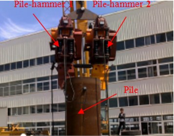
Fig. 6Self-synchronization control test results
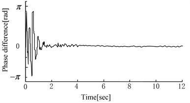
a) Phase self-synchronization process
b) Phase difference after changing speed
c) Self synchronization curve under different speed differences
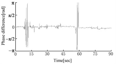
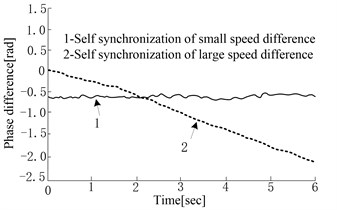
Fig. 6 shows self-synchronization control test results. Fig. 6(a) shows the phase self-synchronization process. Two vibration hammers’ phase differences will tend to be synchronous after 4 s under the effect of control. The phase difference has a small fluctuation. Fig. 6(b) shows the real-time detected phase difference curve when the rotation speed of virtual vibration hammer is suddenly changed in the pile sinking process. It shows that phase difference fluctuates and quickly returns to synchronization when the rotation speed changes. For the complexity of system dynamic response, the electromechanical coupling characteristics of the system become too complex to be predicted. Thus, phase difference has tiny fluctuations in the synchronous process. Fig. 6(c) shows the phase difference curve of self-synchronization when the pile is sunk down to the depth of 3 m. If the rotation speed difference is small, phase difference will fluctuate in a fixed range. The larger the electrical motors’ rotation speed difference is, the farther away from zero the phase difference is and the stronger the fluctuation is. If the rotation speed difference is too large (30 r/min), the system cannot come to self-synchronization.
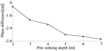
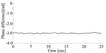
Fig. 7 shows the curve of phase difference’s changes with the pile sinking. When the pile sinks to a certain depth, the stiffness and the damping of the soil reach to the maximum values. The vertical vibration when the rotation rate is 800 r/min is smaller than the one when the pile begins to sink. Phase difference can tend to be zero. When the pile sinks down to the depth of 1 m, the vibration is mainly vertical vibration which is much more than swing vibration; phase difference tends to be ; the excited forces from two vibration hammers are mainly cancelled out; the pile stops sinking. It shows that phase difference can tend to be a value automatically, which will be fluctuant with the pile sinking. The general change trend is that phase difference tends to be larger and larger with the pile sinking.
Fig. 7Phase difference curve changes with the pile penetration
a) Phase difference changes with the pile depth
b) Differential phase changes of 7 m
Fig. 8Synchronization control experimental results
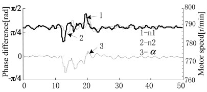
a) Synchronization control curve after disturbance
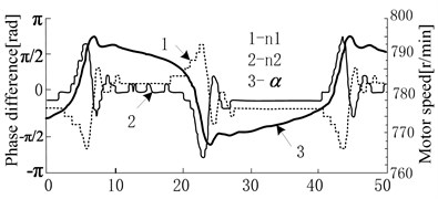
b) Synchronization control curve of 60 % eccentric torque
Fig. 8 shows control synchronization test results. Fig. 8(a) shows the real time measured curve of rotation speed and phase difference changes when pile sinking is interrupted. When one vibratory hammer’s electrical motor rotation speed is interrupted, the rotation speeds of two electrical motors will be adjusted synchronously due to the coupling compensation for rotation speed difference. The adjustment is done to eliminate the rotation speed difference and ensure smaller phase difference fluctuation. Fig. 8(b) shows the synchronization control curve. When eccentric torque comes to 60 %, frequency and phase hopping happens. The system vibration acceleration grows and the load torque of electrical motor increases, then frequency hopping happens on the electrical motor with advanced phase difference first. Phase difference increases quickly, and the load of two electrical motors becomes smaller. The rotation speed increases rapidly and then return to be normal. At last phase difference decreases by the control method. And again, and again, two electrical motors’ rotation speeds turn to mutate in the opposite direction. The vibratory hammer with advanced phase difference mutates first. The synchronization control method is unavailable when the electrical motor’s power is limited. When electrical motors are chosen for designing the vibration system, the biggest acceleration of eccentric block should be considered.
6. Conclusions
The pile hammer linkage system solved the problem that the power is not enough when using one hammer in large diameter pile projects. In order to solve the problem that electromechanical coupling had influences on the control effect of multi-pile hammers linkage, the coupling influence rules were studied. The research results provide the theoretical foundation for the synchronization control strategy of the pile hammer synchronous vibration system. The related conclusions were summarized as follows.
(1) According to the Lagrange equation, the mathematical model was established for the pile hammers linkage system. The proposed system was an electromechanical coupling system. According to the Hamiltonian method, the system conditions of synchronization and stability were derived. Force and energy were transferred among vibration hammers. Strong coupling effect existed in the system. Under certain conditions, the coupling result was that phase difference tended to be a fixed value automatically. The self-synchronization phenomenon of the system appeared. The synchronization condition margin could be increased by adjusting the electromagnetic torque difference and the friction moment coefficient of motor.
(2) The strength of system electromechanical coupling was related to the motor’s mechanical characteristics curve, soil parameters, phase difference, the rotation angle speed and angle acceleration of vibration hammer’s eccentric block. Phase difference tended to be a large value when the pile was sinking, and the synthetic exciting force would be reduced. Coupling effect was transferred by motor’s load torque and reaches to the balance of load torque at last. To get a good synchronous effect for the two vibratory hammers pile sinking system, the mechanical structure, physical dimension and electrical motor’s performance etc., should be consistent, and two electrical motors’ speeds should be equal or close.
(3) The dynamic response of the multi-hammers vibration system was complex and nonlinear. The complexity and nonlinearity of dynamic response between pile and soil, differences of vibration hammer structures and motor characteristics etc., made the electromechanical coupling of the system complex. Moreover, the electromechanical coupling was inherent. Therefore, the self-synchronous mode of vibration hammers was not sufficient for the pile sinking, and it should be the control synchronization mode.
(4) The synchronous control of pile hammer must be carried out based on the matched motor power. Frequency hopping occurs when motor power was insufficient. Under the condition of meeting the power requirements, the fixed phase difference caused by coupling was overcome. Meanwhile, the larger the motor’s power rating was, the stronger the mechanical properties of motor were; the smaller the disturbance influence of vibration system to the dynamical driving system was; the smaller the influence of coupling to the motor’s rotation rate was; the better the controlling effect was.
References
-
Zhi Yongai, Chun Linliu Vertical vibration of a pile in transversely isotropic multi-layered soils. Journal of Sound and Vibration, Vol. 357, 2015, p. 145-155.
-
Hou Yongjun, Yan Guoxing Electromechanical coupling mechanism of self-synchronous vibrating system with three motor driving. Journal of Vibration Engineering, Vol. 19, Issue 3, 2006, p. 354-358.
-
Mahboob I., Nier V., Nishiguchi K., Fujiwara A., Yamaguchi H. Multi-mode parametric coupling in an electromechanical resonator. Applied Physics Letters, Vol. 103, Issue 15, 2013, p. 153105.
-
Cairo R., Conte E., Dente G. Analysis of pile groups under vertical harmonic vibration. Computers and Geotechnics, Vol. 32, Issue 7, 2005, p. 545-554.
-
Kausel E., Roësset J. M. Stiffness matrices for layered soils. Bulletin of the Seismological Society of America, Vol. 71, Issue 6, 1981, p. 1743-1761.
-
Masoumi H. R., Degrande G., Lombaert G. Prediction of free field vibrations due to pile driving using a dynamic soil-structure interaction formulation. Soil Dynamics and Earthquake Engineering, Vol. 27, Issue 2, 2007, p. 126-43.
-
Masoumi H. R., Francois S., Degrande G. Numerical prediction of ground vibrations due to pile driving using a hybrid formulation. 4th International Conference on Earthquake Geotechnical Engineering, Thessaloniki, Greece, 2007.
-
Blekhm An I. I., Fradkov A. L., Tomchina O. P. Self-synchronization and controlled synchronization: general definition and example design. Mathematics and Computers in Simulation, Vol. 58, Issue 4, 2002, p. 367-384.
-
Czolczynski K., Perikowski P., et al. Synchronization of self-excited oscillators suspended on elastic structure. Chaos, Solitons and Fractals, Vol. 32, 2007, p. 937-943.
-
Zhao Chunyu, Zhu Hongtao, Wang Ruizi, et al. Synchronization of two non-identical coupled exciters in a non-resonant vibrating system of linear motion. Shock and Vibration, Vol. 16, Issue 6, 2009, p. 505-515.
-
Zhu Hehua, Xie Yongjian, Wang Huaizhong Analytical solution for pile hammer impact and application of optimum design technique for determining cushion parameters. Journal of Tongji University (Natural Science), Vol. 32, Issue 7, 2004, p. 841-845.
-
Blekhman I. I., Fradkov A. L., Tomchin O. P. Self-synchronization and controlled synchronization: General definition and example design. Mathematics and Computers in Simulation, Vol. 58, 2002, p. 367-384.
-
Wang Feng, Jiang Jianguo, Yan Tianyou Methods of asynchronous motor model simulation based on Matlab. Journal of System Simulation, Vol. 18, Issue 7, 2006, p. 1733-1741.
-
Luo Chunlei, Han Qingkai Synchronization characteristics research of eccentricity ration system controlled by hydraulic driving. Journal of Mechanical Engineering, Vol. 46, Issue 6, 2010, p. 176-181.
-
Pan Fulan Analysis of variation of the coefficient of subgrade rigidity in soil with depth. Acta Mechanica Solida Sinica, Vol. 1, 1981, p. 48-57.
About this article
This work is supported by the National Natural Science Foundations of China (No. 51505290) and Jiangxi Province Key Laboratory of Precision Drive and Control Open Fund Project (PLPDC-KFKT-201622).
