Abstract
From the point of view of frequency capture, the nonlinear dynamic models of the self-synchronous vibrating pile system are presented for the analysis of the nonlinear stiffness of the soil, which is induced by the relationship between the nonlinear stress and the strain in the soil. And the nonlinear dynamic models of the self-synchronous vibrating pile system with electromechanical coupling also are presented for the analysis of the pile- soil- electric coupling. The nonlinear characteristics of the vibrating pile in the self-synchronous vibrating pile system with frequency capture are analyzed, and the periodic solutions for the self-synchronous system with frequency capture are investigated using the nonlinear models. The synchronization condition for the self-synchronous vibrating pile system with frequency capture is theoretical analyzed using the rotor-rotation equations of the two-excited motors, and the synchronization stability condition also is theoretical analyzed using Jacobi matrix of the phase difference equation of the two-excited motors. Using Matlab/Simlink, the reverse rotation synchronization of the two-excited motors and the stability of synchronization of the self-synchronous vibrating pile system with electromechanical coupling are analyzed through the selected parameters. The nonlinear phenomena in the self-synchronous vibrating pile system with electromechanical coupling, such as frequency capture and the limit cycles, are reproduced. Various synchronous phenomena are obtained through the difference rates of the two-excited motors, which are induced by the relationship between the phases of the two-excited motors and the rotation speeds of the two-excited motors. It has been shown that the research results can provide theoretical basis for the design and research of the self-synchronous vibratory system.
1. Introduction
Frequency capture has been an important factor in the vibrating system, and frequency capture is usually explained that the vibration frequency is captured by the first natural frequency when the excitation frequency is close to the definite range of the first natural frequency in the vibrating system [1, 2]. The large amplitude of the vibrating system is very favorable in many engineering field, especially in the self-synchronous vibrating pile system, and the large amplitude can be obtained in the self-synchronous vibrating pile system with frequency capture phenomenon. So frequency capture obtained by the self-synchronous vibrating pile system is very important for performances of the sinking pile. In addition, the exciting force of the vibrating pile system should be vertical sinking into the soil, and a better effect of the sinking pile can be obtained in the vibrating pile system. When the eccentric-blocks on the two excited-motors are the reverse and synchronous rotation in the self-synchronous vibrating pile system, the centrifugal force generated by the rotating eccentric-block can be cancelled by each other on the horizontal direction. And the friction resistance of the pile side can be reduced and the resistance can also be overcome, so the exciting force in the vertical direction is obtained in the vibrating pile system. This vibrating pile system is called as the self-synchronous vibrating pile system, which is including two excited-motor that the eccentric blocks on two excited-motors are the reverse and synchronous rotation. The synchronous rotation can be explained that the phase difference of the two eccentric-blocks is 0 or constant. So investigation on the phase difference of the two eccentric-blocks has become one of the key issues in the self-synchronous vibrating pile system with frequency capture.
Many models of the self-synchronous vibrating pile system, such as the linear model with the linear stiffness of the soil and the simplified ideal model, have been investigated and can be found in many references [3-5]. For the previous research, it had been assumed that the interaction between the pile and the soil was coupled together by linear springs and dampers, and the acting force of the soil in the self-synchronous vibrating pile system was expressed as a linear function [6, 7]. It is no doubt that linear model is a very good model for the analysis of the vibrating pile system, but it is of very limited to describe the acting force of the soil in the vibrating pile system. Firstly, the interaction between the piles and the soil is very complex, and the stress in the soil has a non-linear relation with the strain in the soil, therefore the linear model is not perfect enough. Secondly, the vibrating pile in the soil is self-synchronous vibration, and with the nonlinear nature. If the linear model was used to describe the sinking pile, the self-synchronous vibrating pile system would lose the most essential dynamic phenomena. This linear model cannot describe the nonlinear characteristics, such as the jump phenomenon, frequency synchronization and so on. In addition, the system with the phase synchronization (or speed synchronization) is named as a self-synchronous vibration system, so the investigations on the relationship between the phase difference and the amplitude are essential in the self-synchronous vibrating pile system with frequency capture [8-11], but these investigations can be rarely found in many references.
In this paper, from the point of view of frequency capture, the nonlinear dynamic models of the self-synchronous vibrating pile system with electromechanical coupling also are presented for the analysis of the pile- soil- electric coupling. The synchronization condition and the synchronization stability condition for the self-synchronous vibrating pile system with frequency capture is theoretical analyzed using the rotor-rotation equations of the two-excited motors. Using Matlab/Simlink, the reverse rotation synchronization of the two-excited motors and the stability of synchronization of the self-synchronous vibrating pile system with electromechanical coupling are analyzed through the selected parameters.
2. Mathematical model
The interaction between the piles and the soil has been a nonlinear issue in the self-synchronous vibrating pile system with frequency capture, and which cannot be analyzed using the traditional linear model. From the point of view of the nonlinear relation between the stress and the strain in the soil, the nonlinear characteristics of the interaction between the pile and the soil are expressed using the flexible nonlinear springs. The elastic force of the flexible nonlinear spring can be defined as , where, is the linear elastic stiffness of the soil, is the displacement of the piles, is the linear elastic force, is the nonlinear coefficient of the soil (which is a small integer), is the nonlinear elastic force, and it is usually less than . The vibrating force in the self-synchronous vibrating pile system will be generated by the eccentric blocks with the reverse rotation on the double excited-motors, and this vibrating force is in the vertical direction. The dynamic model of the self-synchronous vibrating pile system is shown in Fig. 1, as shown in Fig. 1, is the coordinate system of the nonlinear vibration system, is the center of the system (it is also the midpoint of the line of the rotating shaft for the two exciter), , is the center of the rotating shaft for the two exciter. Using Lagrange equation, the differential equations of the self-synchronous vibrating pile system under the action of the nonlinear elastic force of the soil are defined as:
Fig. 1The dynamic model of the vibratory pile system
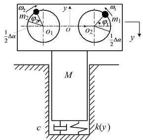
In this equation, , and are the vibration displacement, the velocity and the acceleration of the pile of the vibrating pile system in the vertical direction, respectively, and is the total mass of the vibrating pile system and the total mass is composed of two components, the mass of the vibratory pile hammer and the mass of two eccentric blocks on two excited-motors and , so can be written as , ( 1, 2) is the radiuses of the eccentric block around ( 1, 2), ( 1, 2) is the angular phase of the eccentric block , ( 1, 2) is the angular velocity of the eccentric block , respectively, ( 1, 2) are the angular acceleration of the eccentric block , is the phase difference angle of the eccentric blocks on the two excited motors, is the damping of the soil on the vibrating pile hammer, ( = 1, 2) is the rotating damping of the excited motor , ( 1, 2) is the moment of the inertia of eccentric block , ( 1, 2) is the electromagnetic torque on the excited-motor , ( 1, 2) is the load torque on the excited-motor .
In the paper, three-phase asynchronous motors are chosen as the excited motors in the self-synchronous vibrating pile system with frequency capture, the state equation of the motor is expressed as:
where, , can be expressed as the voltage of the motor in the coordinate system, , are described as the electric current in the rotating coordinate system, respectively, and the subscript 1 and 2 of the electric current are expressed as the stator and rotor respectively. , and are described as the stator winding of the electric machine, the rotor winding of the electric machine and the mutual inductance between the stator winding and the rotor winding. can be described as the pole number of the motor, is the electric angular velocity of the motor stator, and are described as the stator resistance and the rotor conversion resistor of the motor, respectively. can be expressed as the differential operator, namely, . The electromagnetic torque equation of the motor is expressed as the following:
The rotor motion equation of the motor is expressed as the following:
where, is described as the moment of inertia of the rotor system.
Eqs. (1)-(4) constitute a nonlinear dynamic model of the self-synchronous vibrating pile system with the pile- soil-electric coupling, which is named as the model of the self-synchronous vibrating pile system with the electromechanical coupling.
The angular velocity is generated through the rotation of the eccentric block on the exciter-motor and can be expressed as and two angular velocities in the self-synchronous vibration system should be synchronized, which can be named as . The average angularphase of the angular phases may be expressed as , Namely, , . is named as the average speed of two eccentric blocks and can be expressed as , and can been defined as . Where, , , . When , , the eccentricity of the eccentric blocks can be defined as . The first equation in Eq. (1) can be transformed into:
An approximate solution of the self-synchronous vibrating pile system with frequency capture is solved using multi-scale method, and which can be calculated to solve the following equation:
where, , .
In addition, and is named as the first order equivalent natural frequency of the self-synchronous vibrating pile system with frequency capture. Where, and is named as the equivalent stiffness of the self-synchronous vibrating pile system with frequency capture. When the excitation frequency is close to the definite range of the first order equivalent natural frequency, namely, . At this time, the excitation frequency is captured by the natural frequency in the self-synchronous vibrating pile system, and frequency capture occurs in the self-synchronous vibrating pile system.
3. Theoretical analysis
3.1. Theoretical analysis about the synchronization condition
When the phase difference of the two-excited motors is in a certain range, the reverse synchronous operation of the dual excited motor can be realized to run safely and stably in the self-synchronous vibrating pile system. The rotor rotational motion equations (the last two formulas in Eq. (1)) is transformed to obtain the synchronization condition through the theoretical analysis. If frequency capture occurred in the self-synchronous vibrating pile system, the angle frequency of the two excited motor would be equal. is named as average angular frequency of the two excited motor, so the angle frequency of the two-excited motor can be replaced by . It has been assumed that the relevant parameters of the two-excited motor is equal, namely , , , . Then, the last two formulas in Eq. (1) are subtracted from each other, and the rotary motion equation in one period is averaged, and small variables is neglected. Finally, using the last two formulas in Eq. (1), it has been assumed that the relevant parameters of the two-excited motor is equal, the rotary motion equation about the phase difference can be defined as:
If , , Eq. (7) can be transformed into and the state equation of Eq. (7) can be expressed as:
where, is expressed as the difference between the electromagnetic torque and the equivalent load torque. If the state of the stable equilibrium is achieved in the self-synchronous vibrating pile system, , which must be satisfied, namely:
where:
The necessary condition for synchronous operation is that the absolute value of is greater than or equal to 1. So the synchronization condition in the self-synchronous vibrating pile system with frequency capture can be expressed as:
As shown in Eq. (10), if the synchronous and stable operation is achieved in the self-synchronous vibrating pile system with frequency capture, which can be achieved by reducing or increasing . In addition, the difference between the electromagnetic torque and the equivalent load torque is zero, namely, , and it is the ideal condition, but the most unsatisfactory condition is that , namely, in Eq. (10).
The excitation frequency is close to the definite range of the first order equivalent natural frequency in the self-synchronous vibrating pile system with frequency capture, namely, . The self-synchronous vibrating pile system with frequency capture is a flexible nonlinear system, so the first order equivalent natural frequency cannot be identical to the natural frequency in a flexible nonlinear system. Namely, . Therefore is unequal to 0, namely, , and the most unsatisfactory condition (namely, 0) cannot be presented in the self-synchronous vibrating pile system with frequency capture. Eq. (10) can be transformed into and be rewritten as:
If , Eq. (11) can be rewritten as:
The self-synchronous vibrating pile system with frequency capture is a flexible nonlinear system, namely, , and the excitation frequency is close to the definite range of the first order equivalent natural frequency in the self-synchronous vibrating pile system with frequency capture, namely, , so , namely, . Therefore, that () can only be achieved in the self-synchronous vibrating pile system with frequency capture. Here, Eq. (12) can be rewritten as:
When Eq. (13) is satisfied in the self-synchronous vibrating pile system with frequency capture, the reverse synchronous rotation of the two-excited motor can be achieved.
In addition, as shown in Eqs. (10)-(13), if is positive, namely, is negative, the phase different [0°, 90°] or [90°, 180°]. If is negative, namely, is positive, the phase different [–90°, 0°] or [180°, 270°]. Namely, there are two phase difference at each value, and only one solution is stable, and the other one is unstable. Therefore, the synchronous stability condition is analyzed in the self-synchronous vibrating pile system with frequency capture.
3.2. Synchronous stability condition
Using Jacobian matrix in Eq. (8), the synchronous stability condition is deduced in the self-synchronous vibrating pile system with frequency capture. Namely, the synchronous stability condition for the phase different of the two-excited motor are analyzed. Jacobian matrix of Eq. (8) can be expressed as:
The characteristic equation of Jacobi matrix can be written as:
When the real part of the characteristic root is negative in Eq. (15), which can be solved using Hurwits theorem, the phase difference equation is asymptotically stable. The real part of the characteristic root is negative in Eq. (15), which can be satisfied using Hurwits theorem. And the synchronous stability condition must be satisfied and can be expressed as the following:
The self-synchronous vibrating pile system with frequency capture is a flexible nonlinear system, and for the self-synchronous vibrating pile system. When , in Eq. (16). Namely, the phase different is at [–90°, 90°] (namely, [0°, 90°] and [–90°, 0°]). The mean value of the phase difference is 0 at [–90°, 90°], and The self-synchronous vibrating pile system with frequency capture is stable when the phase difference is at [–90°, 90°], but the self-synchronous vibrating pile system is unstable when the phase difference is at [90°, 270°]. So if is negative and the phase difference is at [0°, 90°], the synchronization condition and the synchronization stability condition can be satisfied in the self-synchronous vibrating pile system with frequency capture. If is positive and the phase difference is at [–90°, 0°], the synchronization condition and the synchronization stability condition can be satisfied in the self-synchronous vibrating pile system with frequency capture. In addition, when is 0 and the phase difference is stable at 0, which is the ideal state to meet the reverse synchronous operation of the two-excited motors in the self-synchronous vibrating pile system with frequency capture.
4. Simulation analysis
Using the model of the self-synchronous vibrating pile system with electromechanical coupling (Eqs. (1)-(4)), Some parameters for the self-synchronous vibrating pile system with electromechanical coupling is select as follows: 86 kg, 3.5 kg, 0.08 m, 1552000 N/m, 0.5, 100N∙s/m, 0.01N∙s/m, 0.01N∙s/m, 0.01kg∙m2. And the magnetic pole number of the selected motor is 4 and the excitation frequency of the two-excited motors is 25 Hz (about 157 rad/s). The simulation is performed using Matlab/Simlink, and the responses of the parameters in the model of the self-synchronous vibrating pile system with electromechanical coupling (Eqs. (1)-(4)) has been obtained.
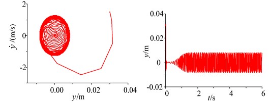
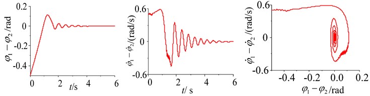
Fig. 2Parameters simulation of the system without frequency capture
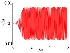
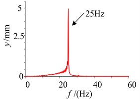
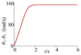
Fig. 3Parameters simulation of the system without frequency capture under different initial conditions
a) Initial velocity (1.5 m/s) and initial displacement (0.03 m)
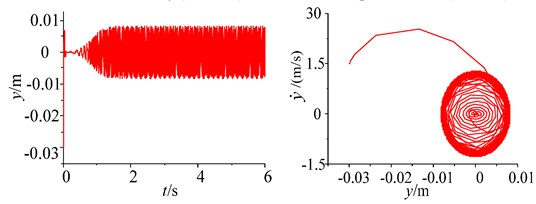
b) Initial velocity (1.5 m/s) and initial displacement (–0.03 m)
From the point of view of simulation analysis, when the damping of the soil is increased (namely, 10000N∙s/m), the responses of the parameters and the phase plane of the vibration displacement in the self-synchronous vibrating pile system with electromechanical coupling (Eqs. (1)-(4)) has been obtained and shown in Figs. 2-3. As shown in Fig. 2, the displacement of the periodic motion is eventually stabilized at about 8mm. But the excitation frequency in the self-synchronous vibrating pile system with electromechanical coupling is about 25 Hz, namely, the speeds of the two-excited motors is eventually stabilized at about 157 rad/s, and the excitation frequency is not captured by the natural frequency, and frequency capture does not occur in the self-synchronous vibrating pile system with electromechanical coupling. In addition, when the initial displacement and the initial velocity is changed in the self-synchronous vibrating pile system with electromechanical coupling, the amplitude of the displacement is not changed, as shown in Figs. 2-3.
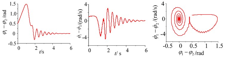
When the damping of the soil is 1000 N∙s/m, the responses of the parameters and the phase plane of the vibration displacement in the self-synchronous vibrating pile system with electromechanical coupling (Eqs. (1)-(4)) has been obtained and shown in Fig. 4. As shown in Fig. 4, after starting the system slowly, the large oscillations of the amplitude in the self-synchronous vibrating pile system with electromechanical coupling can be obtained at the resonance point (about 22.35 Hz), thus the angular frequency of the two-excited motors is captured by the natural frequency, and frequency capture occurs in the self-synchronous vibrating pile system with electromechanical coupling. Then the oscillation of the amplitude is reduced to be stabilized at about 25 Hz (namely, the angular frequency of the two-excited motors), and the speeds of the two-excited motors is eventually stabilized at about 157 rad/s. Finally, the self-synchronous vibrating pile system with electromechanical coupling is still performed under the condition of the angular frequency of the two-excited motors (157 rad/s), the angular frequency of the two-excited motors is not also captured by the natural frequency. The self-synchronous vibrating pile system with electromechanical coupling has occurred frequency capture phenomenon, which is named as critical frequency capture.
Fig. 4Parameter simulation of the system with critical frequency capture
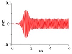
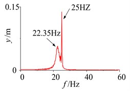
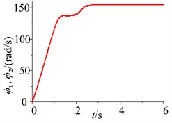
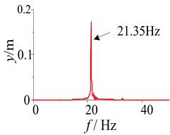
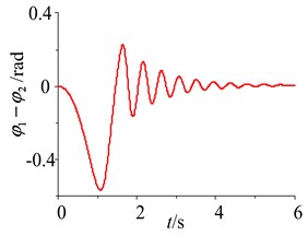
Fig. 5Parameter simulation of the system with frequency capture
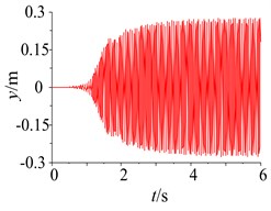
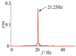
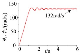
When the damping of the soil is 100 N∙s/m, the responses of the parameters and the phase plane of the vibration displacement in the self-synchronous vibrating pile system with electromechanical coupling (Eqs. (1)-(4)) has been obtained and shown in Fig. 5. When certain parameters of the self-synchronous vibrating pile system with electromechanical coupling are changed appropriately, such as the damping of the soil, the excitation frequency is close to the definite range of the first natural frequency, and the excitation frequency is captured by the first order equivalent natural frequency in the self-synchronous vibrating pile system with electromechanical coupling. As shown in Fig. 5, when the system is slowly started, and the working frequency is not changed after the resonance point (about 21.25 Hz), the response tends to be stable and does periodic motion in the self-synchronous vibrating pile system with electromechanical coupling, and the displacement of the periodic motion is eventually stabilized at about 0.28 m. As shown in Fig. 5 (motor speed diagram), the speeds of the two-excited motors is eventually stabilized at about 132 rad/s and also slightly less than the first order natural frequency (about 134 rad/s), it also has been confirmed that the speeds of the two-excited motors are not the speed (about 157 rad/s) under the condition of their own vibration frequency, and the angular frequency of the two-excited motors is captured by first order equivalent natural frequency (about 21.25 Hz). The self-synchronous vibrating pile system with electromechanical coupling occur frequency capture phenomenon, which is named as frequency capture. As shown in Figs. 2-5, when frequency capture occurs in the self-synchronous vibrating pile system with electromechanical coupling, the amplitude of the system is much greater than the amplitude of the system without the frequency capture. The large amplitude is beneficial to the speed of the pile and the efficiency of the pile, so the self-synchronous vibrating pile system with frequency capture should be rational use. But the synchronous rotation of the two excited motor is very sensitive to the resonance of the system, and it is easy to cause the instability when frequency capture occurs the self-synchronous vibrating pile system with electromechanical coupling. So the reverse synchronous operation of the two-excited motors and the synchronization stability of the self-synchronous vibrating pile system should be analyzed in detail.
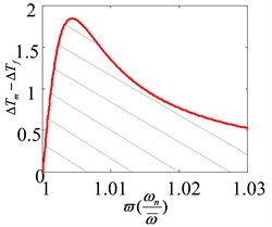
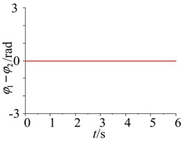
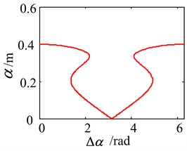
The simulation diagrams of the parameters in the self-synchronous vibrating pile system with frequency capture are shown in Fig. 6. The first diagram in Fig. 6 is obtained by Eq. (13), the difference between the electromagnetic torque and the equivalent load torque must be in the shadow range, and the reverse synchronous rotation of the two-excited motor can be achieved and frequency capture can occur in the self-synchronous vibrating pile system. When frequency capture occurs in the self-synchronous vibrating pile system with electromechanical coupling, the excited frequency (namely, the angular frequency of the two-excited motors) is captured by the first order equivalent natural frequency (about 132 rad/s), namely, the excited frequency can be replaced by the first order equivalent natural frequency. Using the selected parameters, when the ratio between the first natural frequency (134 rad/s) and the excitation frequency (132 rad/s) is 1.0176, the difference between the electromagnetic torque and the equivalent load torque must be less than 0.845 and in Eq. (10) can be greater than 1, and the reverse synchronous rotation of the two-excited motor can be achieved in the self-synchronous vibrating pile system. As shown in the second diagram of Fig. 6, when the initial phase difference and the initial rotational speed difference also are 0, the phase difference (or the rotational speed difference) of the two-excited motors are always 0. As shown in the last diagram of Fig. 6, the relationship between the phase difference and the amplitude of the periodic solution for the self-synchronous vibrating pile system with electromechanical coupling has been obtained by using implicit equations between the phase difference and the amplitude. When the phase difference is at 0 or 2, the maximum amplitude can be obtained at 0 or 2. But the phase difference is at, the amplitude is 0, namely, if the two-excited motors are the reverse synchronous operation, the phase difference must be in the range of 0 (or 2), and the maximum amplitude can be obtained. Thus the phase difference is at 0 or 2, It is very ideal to meet the reverse synchronous operation of the two-excited motors in the self-synchronous vibrating pile system with frequency capture, which is consistent with theoretical analysis.
In theoretical analysis, it has been discussed that the self-synchronous vibrating pile system with frequency capture tend to be stable when the phase difference is at [–90°, 90°]. And when is 0, it is the ideal state for the self-synchronous vibrating pile system with frequency capture. Namely, the difference rate of the two-excited motors is 0 and the phase difference of the two-excited motors is 0, and the ideal state for the self-synchronous vibrating pile system with frequency capture can be obtained. But the two excited motors cannot be completely consistent in actual engineering, the difference rate of the two-excited motors cannot be avoided. So the synchronous operation of the two-excited motors and the stability of synchronization for the self-synchronous vibrating pile system with electromechanical coupling must be quantitative analyzed.
Fig. 6The simulation diagrams of the parameters
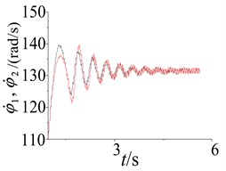
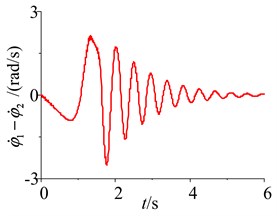
When the initial phase (namely, the initial phase difference is 1rad) of the two-excited motors and the initial rotational speed (namely, the initial rotational speed difference is 0.5 rad) of the two-excited motors are different, the parameters responses of the self-synchronous vibrating pile system with electromechanical coupling are shown in Fig. 7. As shown in Fig. 7, after a big shock has been presented for the rotational speeds of the two-excited motors, finally, the rotational speeds of the two-excited motors also are stable at around 132 rad/s and do periodic motion. Hence, when the difference rate of the two-excited motors is considered, the excited frequency can still be captured by the first order equivalent natural frequency, namely, frequency capture can still occur in the self-synchronous vibrating pile system with electromechanical coupling, and the reverse synchronous operation of the two-excited motors and the stability of synchronization of the self-synchronous vibrating pile system with electromechanical coupling can be achieved.
Fig. 7The system parameter response in different initial conditions
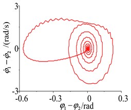
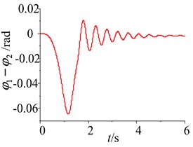
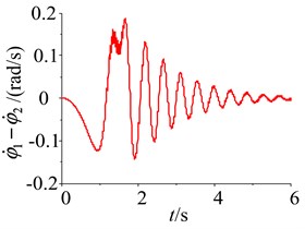
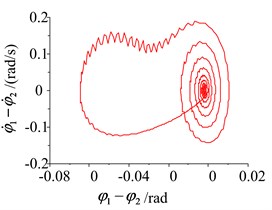
When the difference rates of the two-excited motors are shown in the self-synchronous vibrating pile system with electromechanical coupling, the stabilities problems of the phase difference and the rotational speed difference for the two-excited motors are analyzed in the following. The simulation of the system parameters is performed using Matlab/Simlink, and the responses and the phase plane of the phase difference and the rotational speed difference are shown in Figs. 8-11, when the difference rates of the two-excited motors are selected, such as the different initial phase, the different initial rotational speed, the parameter difference of the two-excited motors and the different rotational damping of the excited motor rotor. As shown in Figs. 8-11, as a result of some differences between the two-excited motors, wherever the initial point of the phase difference and the rotational speed difference are, the phase difference and the rotational speed difference of the two-excited motor are all experienced a gentle transition process, then a high fluctuations of the phase difference and the rotational speed difference are obtained in the self-synchronous vibrating pile system with electromechanical coupling, finally, the phase difference is stable at 0 or 2 and the rotational speed difference is stable at 0, which is consistent with theoretical analysis.
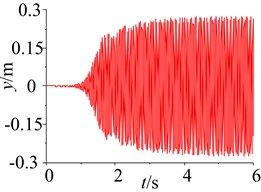
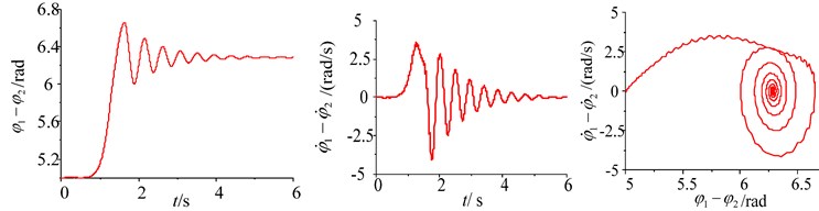
Fig. 8Simulation of the system with frequency capture in different initial phase conditions
a) The initial phase difference (5 rad)
b) The initial phase difference (1.57 rad)
Fig. 9Simulation of the system with frequency capture in different initial rotational speed conditions
a) The initial phase difference (–0.5 rad) and the initial rotational speed difference (0.5 rad)
b) The initial phase difference (0.5 rad) and the initial rotational speed difference (1 rad)
Fig. 10Simulation of the system with frequency capture in the difference of the motors parameters
So when the difference rates of the two-excited motors is in a certain range, the two-excited motor can restore the synchronization by itself, and the phase difference is stable at 0 or 2 and the rotational speed difference is stable at 0, namely, when frequency capture occurs, the reverse synchronous operation of the two-excited motors and the synchronous stability operation of the self-synchronous vibrating pile system with electromechanical coupling can be obtained to achieve the large amplitude of the pile and the pile speed, and to improve the efficiency of the pile.
Fig. 11Simulation of the system with frequency capture in the difference of the rotating damping
5. Conclusions
1. From the point of view of frequency capture (the excited frequency of the excited motor is captured by the first order equivalent natural frequency, namely, ), the synchronization condition of the two-excited motors and the synchronous stability condition is theoretical discussed, and using the relationship between the phase difference and the amplitude of an approximate solution, the synchronization and the synchronous stability are analyzed. It has been shown that the phase difference is stable at 0 or 2, the synchronous stability condition can be achieved in the self-synchronous vibrating pile system.
2. Based on the model of the self-synchronous vibrating pile system with the electromechanical coupling, the reverse synchronous operation of the two-excited motors and the synchronous stability of the self-synchronous vibrating pile system have been quantitative analyzed in the self-synchronous vibrating pile system with electromechanical coupling. It has shown that the amplitude of the system is much greater than the amplitude of the system without the frequency capture when frequency capture occurs in the self-synchronous vibrating pile system with electromechanical coupling. The large amplitude is beneficial to the speed of the pile and the efficiency of the pile, so the self-synchronous vibrating pile system with frequency capture should be rational use. when the difference rate of the two-excited motors is considered, the excited frequency can still be captured by the first order equivalent natural frequency, namely, frequency capture can still occur in the self-synchronous vibrating pile system with electromechanical coupling, and the reverse synchronous operation of the two-excited motors and the stability of synchronization of the self-synchronous vibrating pile system with electromechanical coupling can be achieved.
3. Frequency capture phenomenon in the self-synchronous vibrating pile system with electromechanical coupling are presented for the changes of the system parameters (including the damping of the soil), and various synchronous phenomena of the self-synchronous vibrating pile system with electromechanical coupling are obtained through the difference rates of the two-excited motors (including the initial phase difference, the initial rotational speed difference, the difference of the motors parameters and the difference of the rotating damping). When the difference rates of the two-excited motors is in a certain range, the two-excited motor can restore the synchronization by itself, and the phase difference is stable at 0 or 2 and the rotational speed difference is stable at 0, namely, when frequency capture occur, the reverse synchronous operation of the two-excited motors and the synchronous stability operation of the self-synchronous vibrating pile system with electromechanical coupling can be obtained to achieve the large amplitude of the pile and the pile speed, and to improve the efficiency of the pile.
References
-
Blekhman I. I., Fradkov A. L., Tomchina O. P., Bogdanov D. E. Self-synchronization and controlled synchronization: general definition and example design. Mathematics and Computers in Simulation, Vol. 58, Issues 4-6, 2002, p. 367-384.
-
Zhao C. Y., Zhu H. T., Zhang Y. M., Wen B. C. Synchronization and general dynamic symmetry of a vibrating system with two exciters rotating in opposite directions. Chinese Physics B, Vol. 19, Issue 3, 2010, p. 1-7.
-
Paz M., Cole J. D. Self-synchronization of two unbalanced rotors. Journal of Vibration and Acoustics, Vol. 114, Issue 1, 1992, p. 37-41.
-
Panovko G. Y., Shokhin A. E., Eremeikin S. A. Experimental analysis of the oscillations of a mechanical system with self-synchronized inertial vibration exciters. Journal of Machinery Manufacture and Reliability, Vol. 44, Issue 6, 2015, p. 492-496.
-
Hou Y. J., Yan G. X. Electromechanical-coupling mechanism of self-synchronous vibrating system with three-motor-driving. Journal of Vibration Engineering, Vol. 19, Issue 3, 2006, p. 354-358.
-
Luo C. L., Han Q. K. Synchronization characteristics research of eccentric gyration system controlled by hydraulic driving. Journal of Mechanical Engineering, Vol. 46, Issue 6, 2010, p. 176-181.
-
Lai X., Wu J. Z., Ruan B., Zhang D. B. Numerical simulation and experiments on electromechanical coupling characteristics of pile hammer synchronous vibration system. Journal of Mechanical Engineering, Vol. 25, Issue 2, 2012, p. 167-173.
-
Li X. H., Liu J., Liu J. T. Analysis of harmonic oscillation synchronization for the single-mass nonlinear system under harmonic wave sharp resonance conditions. Journal of Mechanical Engineering, Vol. 46, Issue 1, 2010, p. 86-91.
-
Li L., Ye H. The existence stability and approximate expressions of periodic solution of strongly nonlinear non-autonomous systems with multi-degree-of-freedom. Nonlinear Dynamics, Vol. 46, Issue 2, 2006, p. 87-111.
-
Li X. H., Chen S. P., Liu J. Harmonic vibration synchronization analysis of nonlinear vibration system based on frequency catching phenomenon. Journal of Mechanical Engineering, Vol. 50, Issue 3, 2014, p. 100-107.
-
Olusola O. I., Vincent U. E., Njah A. N. Synchronization, multi-stability and basin crisis in coupled pendular. Journal of Sound and Vibration, Vol. 329, Issue 4, 2010, p. 443-456.
Cited by
About this article

The author gratefully acknowledges that the work was supported by the science research foundation of Beijing University of Civil Engineering and Architecture under the Project No. 00331616043.
