Abstract
In order to study the electromechanical coupling dynamics characteristics of the drive motor and gear transmission system in the electric vehicle electric drive system, firstly, an electromechanical coupling dynamics model of the electric vehicle electric drive system is established; the electromechanical coupling vibration characteristics of the electric drive system under current harmonic excitation is compared and analyzed. The influence law of permanent magnet synchronous motor current harmonics on the meshing vibration of gear transmission system is revealed. The simulation results show that there is an obvious electromechanical coupling effect in the electric drive system; the harmonics of the drive motor can aggravate seriously the vibration state of the mechanical drive system; the research results provide a theoretical reference for further research on the vibration source positioning and active vibration reduction control strategy for the electric drive system of electric vehicles.
Highlights
- An electromechanical coupling dynamics model of the electric vehicle electric drive system is established
- The electromechanical coupling vibration characteristics of the electric drive system under current harmonic excitation is analyzed
- The influence law of permanent magnet synchronous motor current harmonics on the meshing vibration of gear transmission system is revealed
1. Introduction
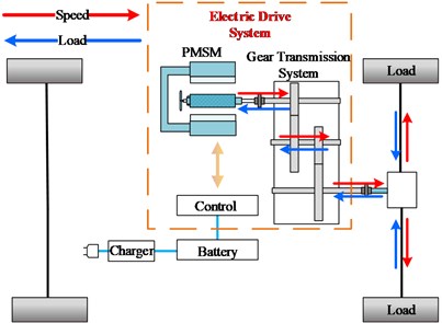
The electric drive system is one of the core components of electric vehicles, and its performance directly affects the safety and reliability of electric vehicles. The electric drive system is mainly composed of a drive motor and a gear transmission system, which is a typical electromechanical coupling system. As the electric drive system develops towards high speed and integration, the problem of coupled vibration has become more prominent, and seriously deteriorating the reliability and dynamic characteristics of the electric drive system of electric vehicles.
In recent years, the electromechanical coupling characteristics of electric drive systems have become a research hotspot for scholars. Yi et al. [1] established a shearer cutting system dynamic model including a cutting motor and a cutting drive system, and the influence of electromagnetic stiffness on the inherent characteristics of the gear system was studied. Chen [2] established a permanent magnet synchronous motor model of hybrid electric vehicles based on park transform and Fourier transform, which considered magnetic tension, saturated magnetic field, space harmonics and other factors, and the influence of electromagnetic parameters and structural parameters on the vibration of the electromechanical coupling system was studied.
Wenyu Bai et al. [3-4] considered factors such as the material of the motor with constant inductance, the spatial distribution of the magnetic field and the time-varying stiffness of the transmission system, and then, an electromechanical coupling dynamic model including the flux network motor and planetary gears was established. The study found that during process of transient change of voltage and loads, the electromechanical coupling system would vibrate violently, especially under the excitation of voltage transients.
Abraham G. [5] established a motor simulation model based on park transformation, and the influence of the number of electrodes and stator slots on the electromagnetic torque ripple of the motor was studied. Literatures [6-8] established a shearer cutting system dynamic model including a cutting motor and a cutting drive system, and the influence of internal and external excitation on the torsional vibration of the electromechanical coupling system under variable-speed and variable-load conditions was studied.
Although the above literatures have studied the electromechanical coupling dynamics in the fields of shearer cutting systems, high-speed train traction systems and permanent magnet synchronous motors, there are few studies on electromechanical coupling systems that consider harmonic problems. The harmonic content in the harmonic current will increase the loss of the motor, aggravate the electromagnetic torque fluctuation of the motor, and affect the service life and operating efficiency of the motor. The torque fluctuation of the motor will bring noise and vibration. In severe cases, the electric drive system may resonate and even damage the shaft of the motor. Therefore, considering the harmonic problem, it can truly reflect the electromechanical coupling dynamics of the electric drive system of electric vehicles, and provide a theoretical basis for suppressing the torsional vibration of the electric drive system [9-10].
Zhao et al. [11] ignored the nonlinear force generated by the gear meshing of the transmission system, an electromechanical coupling dynamics model of the high-speed train traction-transmission system was established, and studied the influence of motor harmonics on the dynamic characteristics of the electromechanical coupling system. P. Pellerey [12] et al. established 2D and 3D finite element models of the motor, and verified that optimizing current harmonics can reduce motor vibration. Literature [13] analyzed the causes of motor torque fluctuations in electric vehicles from two aspects: motor structure and motor controller, and the influence of motor torque fluctuations on the transmission system was studied. The influence of multiple design variables on torque ripple was analyzed in literature [14] and the 6-order torque ripple signal of motor torque through measurement experiments was obtained. Aiming at the 5th and 7th harmonics, the control strategy was proposed in literature [15] which could effectively reduce the torque ripple of 6 times the current frequency, and reduce the vibration amplitude of the drive system at the high frequency natural frequency.
In summary, although there are many literatures on the harmonic issues of motor systems, there are relatively few studies on the impact of current harmonic excitation on the electric drive system of electric vehicles.
Therefore, the purpose of this paper is to establish the electromechanical coupling dynamic model of the electric drive system (as shown in Fig. 1) on the basis of considering the nonlinear factors such as the harmonic current of the motor and the nonlinear dynamics of the gear, and analyze the influence of the permanent magnet synchronous harmonic current on the gear drive system, so as to provide theoretical reference for further suppressing the vibration of the electric drive system of the electric vehicle.
Fig. 1Schematic diagram of electromechanical coupling model of electric vehicle electric drive system
2. Electromechanical coupling dynamics model of electric drive system of electric vehicle
2.1. Permanent magnet synchronous motor model
The gear transmission system is driven by a permanent magnet synchronous motor. An equivalent circuit model of a permanent magnet synchronous motor is established under the d-p coordinate axis with the park transformation theory. And the corresponding voltage equation and electromagnetic torque equation are as follows:
where and denote the and axis voltages respectively; and denote the d and q axis currents respectively; denotes the fundamental voltage angular velocity; denotes the motor stator resistance; and denote the permanent magnet flux linkage components on the and axes, respectively.
The stator flux equations are:
where and denote the and axis inductance parameters respectively; denotes the permanent magnet flux linkage parameters.
Incorporating Eq. (1) into Eq. (2), the stator voltage equation can be obtained as:
The electromagnetic torque equation at this time is:
where denotes the number of pole pairs of the motor; denotes electromagnetic torque of permanent magnet synchronous motor.
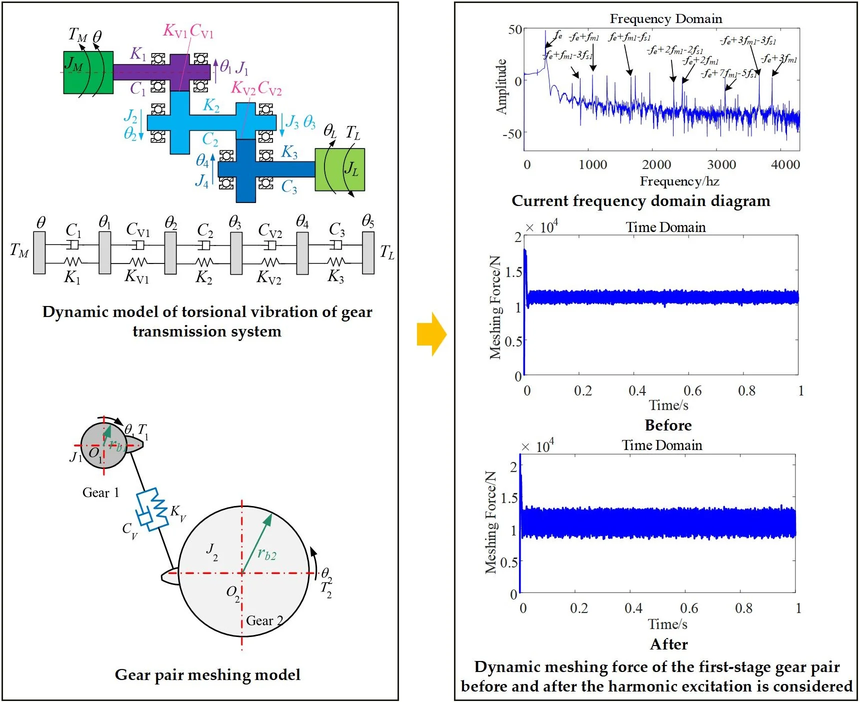
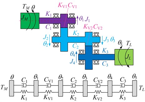
2.2. Dynamic model of torsional vibration of gear transmission system
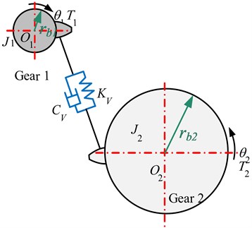
2.2.1. Gear pair meshing force model
In this paper, the lateral and axial deformation of the transmission shaft is ignored, the torsional vibration of the gear is considered, and a two-degree-of-freedom gear pair torsional vibration model is established, as shown in Fig. 2.
The dynamic normal meshing force of the gear including meshing damping can be expressed as:
where denotes the serial number of the gear involved in the meshing: 1, 2; and denotes the comprehensive meshing stiffness and damping coefficient of the gear pair at the meshing point; and denote the base circle radii of the two gears; and respectively denote the rotation angles of the two gears.
The torque balance equation of the driving and driven gears is:
where and denote the rotation angles of the main and driven gears respectively, and and denote the moments of inertia of the two wheels respectively. and denote driving torque and resistance torque. Use to represent the dynamic transmission error of the gear, , then the clearance function as follows:
where, denotes the gear pair clearance; when , the gear teeth are in a normal meshing state; when , the gear teeth are in a separated state; when , the meshing gear teeth are in the meshing state of the tooth back.
Fig. 2Gear pair meshing model
2.2.2. Dynamic model of torsional vibration of gear system
Fig. 3 shows the torsional vibration dynamics model of the gear transmission system. Comprehensively consider the rigid body rotation and elastic torsional vibration of the gear transmission system, and establish the dynamic equations of each component of the transmission system, as shown in Eq. (9).
, , , denote the moments of inertia of the motor, load and the main and driven wheels respectively; , , and denote the rotation angles of the motor, load and the main and driven gear respectively; and denote respectively the main and driven shafts; the torsional stiffness coefficients of and denote respectively the torsional damping coefficients of the master and slave shafts.
Considering the characteristics of the motor, taking into account the speed fluctuations of the motor, and , , , and can be taken as the generalized coordinates of the system, the dynamic equation of the system denotes established by the Newton-Euler method as follows:
where , , , and denote the base circle radii of the four gears respectively, and and denote the dynamic meshing forces between the first and second pairs of gear teeth:
where and denote driving torque and load torque respectively; and denote gear meshing damping coefficients respectively; and denote gear meshing stiffness coefficients respectively. Substituting the change law of and into this equation, the angle change law of the motor can be obtained, that is, the speed fluctuation can be obtained.
Fig. 3Dynamic model of torsional vibration of gear transmission system
3. Dynamics analysis of electromechanical coupling in electric drive system of electric vehicle
3.1. Model validation
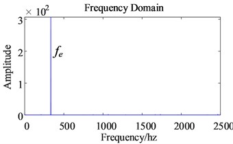
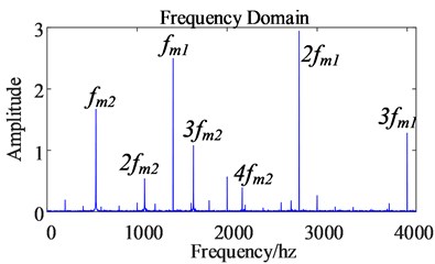
In order to verify the established dynamic model and research the coupling relationship between the mechanical signal and the electrical signal in the electric drive system of electric vehicles under steady-state conditions, constant speed and constant load conditions are applied to the electric drive system, and the meshing force and speed of the mechanical system under this condition are analyzed and studied. And the frequency components in the current signal of the electrical system. (= 1, 2) represents the meshing frequency of the gear pairs from the motor to the load end, (= 1, 2, 3) represents the rotation frequency of the transmission shafts from the motor to the load end.
3.1.1. Simulation results
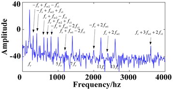
The simulation results are shown in Fig. 4. From the permanent magnet synchronous motor stator current spectrum diagram, it can be seen that although the stator current frequency is mainly , the power frequency, the meshing frequency information of the gear pair and the transmission shaft rotation frequency signal appear at the same time. (= 1400 hz, = 2800 hz, = 4200 hz, = 541.92 hz, = 1083.84 hz, = 1625.76 hz, = 2167.68 hz, = 2709.6 hz, = 3251.52 hz, = 3793.44 hz, = 66.67 hz, = 7.32 hz). Take as an example, the in this frequency represents the power frequency. But because the permanent magnet synchronous motor and the transmission system are directly connected, the electric drive system is modulated between the mechanical system and the electrical system during operation. The power supply frequency is modulated by the first-stage gear pair meshing frequency and the input shaft rotation frequency , so the final frequency is modulated to . The other current frequency modulation principles marked in the figure are similar to the above, and will not be repeated.
Fig. 4Simulation results of three-phase current of permanent magnet synchronous motor
a) Time domain diagram
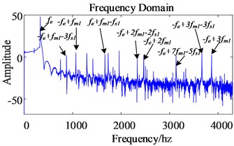
b) Frequency domain diagram
3.1.2. Experiment test results
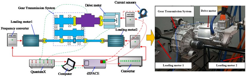
In order to verify the proposed model, the Electric Drive System is tested on the three-motor test stand (Fig. 5) to obtain test data. One whole electric drive system is selected for the test. The drive motor of the test bed is directly connected to the two-staged gear transmission using a rigid shaft, the two electric dynamometer (loading moter1 and loading moter 2) are connected to the two half shafts of the transmission to simulate the load torque. Hall current sensor is adopted to detect the current of drive machine. dSPACE is employed to develop the real-time control system of the test rig.
Fig. 5Experiment test rig schematic diagram and physical drawing (Photo from Key Laboratory of Advanced Manufacturing Technology for Automobile Parts, Chongqing University of Technology)
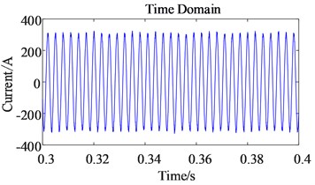
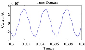
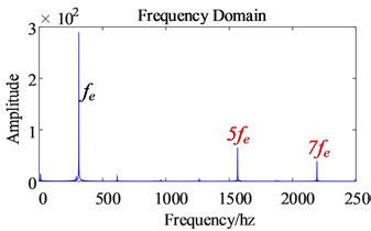
The experiment test results of three-phase current of permanent magnet synchronous motorare shown in Fig. 6. Through the analysis of the test results and simulation results, it can be seen that the motor current frequency is modulated by the rotation frequency and meshing frequency in the gear drive system in the form .In addition to the internal mechanical system of the electric drive system of an electric vehicle, the electrical system and the mechanical system will also influence each other. During the operation of the electric drive system, the electric system not only unilaterally transmits the torque and speed to the mechanical system, but is also affected by the mechanical system. The electric signal contains a wealth of gear pair meshing frequencies and transmission shaft rotation frequency signals. This also proves that the electromechanical coupling characteristics exist in the established electromechanical coupling dynamic model of the electric drive system of electric vehicles, and verifies the effectiveness of the dynamic model.
Fig. 6Experiment test results of three-phase current of permanent magnet synchronous motor
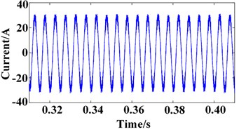
a) Time domain diagram
b) Frequency domain diagram
3.2. Dynamic analysis of electromechanical coupling of electric drive system with considering time harmonic factors
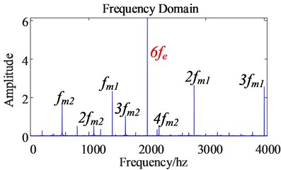
When the permanent magnet synchronous motor has three-phase design imbalance, current or angle sampling error, inverter dead zone, etc., it is very easy to cause undesired 6±1 in the controlled current (= 1, 2, 3,...) order of harmonic currents, which in turn will cause the permanent magnet synchronous motor torque to produce 6 (= 1, 2, 3,...) order of harmonics, which aggravates the electromagnetic torque pulsation of the motor. Among them, the 5th and 7th order harmonic components have the most obvious influence on the electromagnetic torque fluctuation of the permanent magnet synchronous motor (the content of the remaining harmonics decreases in order), which will cause the electromagnetic torque to produce the 6th harmonic torque.
This paper mainly takes the 6th order harmonic torque generated by the 5th and 7th order harmonic currents as the research object. On the basis of the established permanent magnet synchronous motor model, establish a permanent magnet synchronous motor model considering the 5th and 7th order time harmonic factors (the other order time harmonic models are established in the same way, so will not be repeated).
The three-phase voltage of a permanent magnet synchronous motor with 5th and 7th order harmonics can be expressed as:
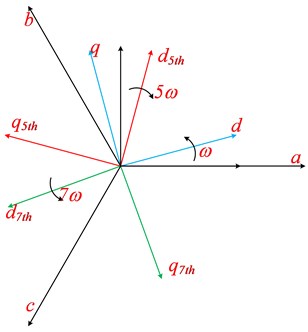
where, , , denote the fundamental wave, 5th order, 7th order harmonic voltage amplitude respectively;, , denote the fundamental wave, the initial phase angle of the 5th and 7th order harmonic voltage. Transform the voltage equation containing harmonics to the 5th-order harmonic synchronous rotating coordinate axis system (as shown in Fig. 7) to obtain Eq. (13). Where and denote the amplitudes of the 5th order harmonic current under the synchronous rotating coordinate axis, respectively:
Fig. 7The 5th and 7th order synchronous rotating coordinate axis system
Since the fundamental wave and the 7th-order harmonic are both AC components under the 5th-order harmonic synchronous rotation coordinate axis system, the terms containing the AC quantity in the formula are discarded, and the 5th-order harmonic steady-state voltage equation in the 5th-order harmonic synchronous rotating coordinate system is obtained, as shown in Eq. (14):
In the same way, transform Eq. (12) to the 7th order harmonic synchronous rotating coordinate axis system, and discard the items containing the alternating current to obtain the 7th order harmonic steady state voltage equation under the synchronous rotating coordinate axis system:
where, and denote respectively the amplitudes under the 7th-order harmonic synchronous rotating coordinate axis system.
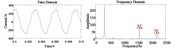
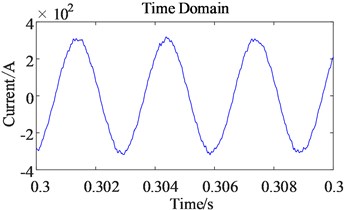
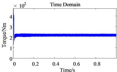
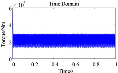
The three-phase current simulation results of the motor model are shown in Fig. 8. Although the frequency domain diagram of the stator three-phase current is dominated by (333.33 hz) frequency, it contains obvious 5th and 7th order harmonic currents. In addition, the waveform of the stator current is no longer an ideal sinusoidal waveform, but is distorted.
The stator current of the motor contains the 5th and 7th order harmonics. After the / coordinate conversion, the 5th and 7th order harmonics are converted into the 6th order harmonic currents, so the current also contains the harmonic components due to time harmonic factors. In addition, the electromagnetic torque shown in Eq. (4) is related to the current , so the electromagnetic torque of the permanent magnet synchronous motor also contains harmonic components due to time harmonic factors, which is 6 marked in Fig. 8(a).
Fig. 8Dynamic analysis of electromechanical coupling of electric drive system with considering time harmonic factors
a) The three-phase current time-frequency diagram of a permanent magnet synchronous motor considering harmonic excitation
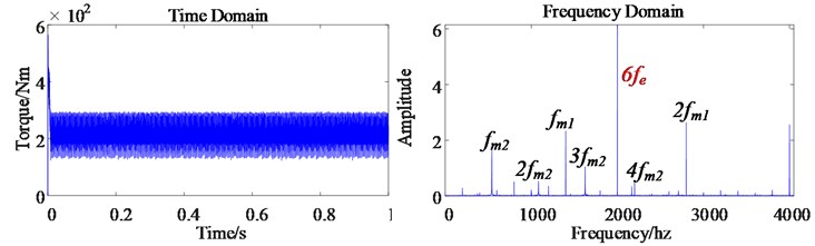
b) The electromagnetic torque dynamic response of permanent magnet synchronous motor
c) Dynamic response of output speed of permanent magnet synchronous motor
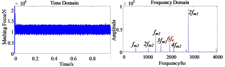
d) The dynamic meshing force of the first-stage gear pair
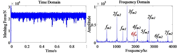
e) The dynamic meshing force of the second-stage gear pair
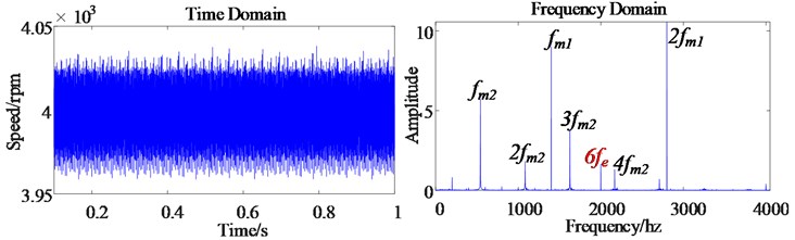
Harmonic components increase the electromagnetic torque pulsation of the motor. Because the electromagnetic torque is directly applied to the motor rotor, the motor output speed also contains 6th order harmonics (as shown in Fig. 8(b) and Fig. 8(c)), which causes the motor output speed pulsation to become obvious, which reduces the control accuracy of the motor.
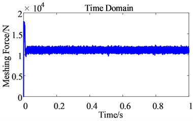
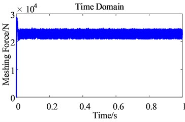
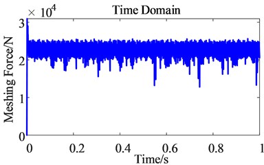
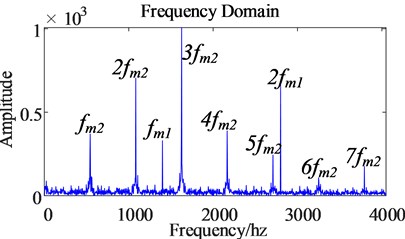
Fig. 8(d) and (e) show the time domain diagram and frequency domain diagram of the first-stage gear pair dynamic meshing force and the second-stage gear pair dynamic meshing force of the transmission system in the electric drive system of an electric vehicle. Because of the electromechanical coupling characteristics in the electric drive system of electric vehicles, the mechanical transmission system is affected by the electrical system, and the meshing frequency of the gear pair of the gear transmission system also contains the corresponding 6th order harmonics. It can be seen from the simulation results that the electrical system and mechanical system in the electric drive system of electric vehicles will be affected by time harmonics, which aggravates the vibration amplitude of the electric drive system.
3.3. Dynamic analysis of electromechanical coupling of electric drive system before and after considering time harmonics
Comparing the time domain (as shown in Fig. 9) with frequency domain (as shown in Fig. 10) of the three-phase current before and after considering the time harmonic factor, it is found that the main influence of time harmonics on the three-phase current is the increase of the 5th and 7th order harmonics. The harmonics of the order of the other orders did not change significantly. The increased 5th and 7th order harmonics have distorted the original sinusoidal three-phase current waveform. Although Fig. 9(a) contains low energy high frequency, the amplitude is smaller than that of , so it is not shown in Fig. 10(a).
Fig. 9Time domain comparison of three-phase current before and after harmonic excitation
a) Before
b) After
Fig. 10Comparison of three-phase current frequency domain before and after harmonic excitation
a) Before
b) After
Since the 5th and 7th order harmonics in the stator current of the permanent magnet synchronous motor are transformed into the 6th order harmonic current under the coordinate axis after coordinate transformation, and because is related to electromagnetic torque, the harmonic current of generates electromagnetic torque harmonics of the corresponding order through electromagnetic induction. So by comparing the electromagnetic torque time domain diagram and frequency domain diagram before and after the harmonic current is considered, it can be found that after considering the harmonics, the electromagnetic torque ripple range of the motor becomes larger, and the amplitude of the 6th order harmonics of the torque is significantly increased.
Fig. 11Time domain comparison of electromagnetic torque before and after harmonic excitation
a) Before
b) After
Fig. 12Frequency domain comparison of electromagnetic torque before and after harmonic excitation
a) Before
b) After
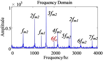
The input shaft of the gear transmission system is the rotor of a permanent magnet synchronous motor. The harmonic current and the magnetic field generated by the permanent magnet produce electromagnetic induction, which causes the electromagnetic torque to contain 6th order harmonics, which makes the motor output speed also contain 6th order harmonic, so the output speed pulsation of the motor becomes larger, which reduces the control accuracy of the motor. The permanent magnet synchronous motor transmits the output speed to the gear transmission system, and at the same time transmits the 6th order harmonics to the gear transmission system, so the 6th order harmonics also appear in the dynamic meshing force of the gears (as shown in Fig. 11-12).
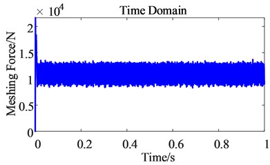
From the time domain diagram of the dynamic meshing force of the first-stage gear pair (as shown in Fig. 13), the pulsation range of the dynamic meshing force of the gear becomes larger after considering the time harmonics, which intensifies the vibration amplitude of the gear transmission system. From the frequency domain diagram of the dynamic meshing force of the first-stage gear pair (as shown in Fig. 14), the frequency domain after considering the time harmonic is only one more than the frequency before considering the time harmonic, indicating that the frequency is the main reason for the increased pulsation of the dynamic meshing force of the gear pair.
From the time domain diagram of the dynamic meshing force of the second-stage gear pair (as shown in Fig. 15), the dynamic meshing force of the gear pair after considering the time harmonics produces slight pulsation. It can be seen that time harmonics can intensify the dynamic meshing force pulsation of the second-stage gear pair.
Fig. 13Frequency domain comparison of the dynamic meshing force of the first-stage gear pair before and after the harmonic excitation is considered
a) Before
b) After
Fig. 14Frequency domain comparison of the dynamic meshing force of the first-stage gear pair before and after the harmonic excitation is considered
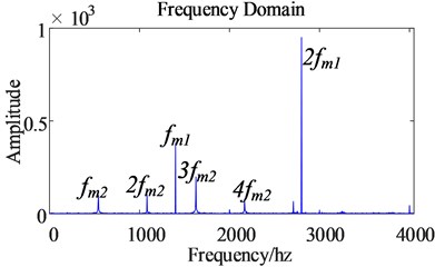
a) Before
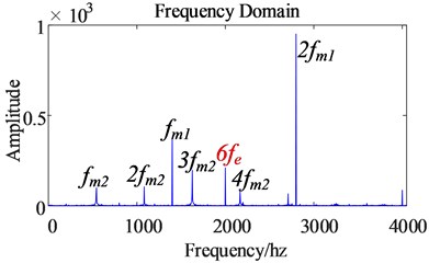
b) After
Fig. 15Time domain comparison of the dynamic meshing force of the second-stage gear pair before and after the harmonic excitation is considered
a) Before
b) After
From the frequency domain diagram of the dynamic meshing force of the second-stage gear pair (as shown in Fig. 16), time harmonics cause the dynamic meshing force of the second-stage gear pair to generate a frequency of 6, which intensifies the dynamics of the second-stage gear pair. The meshing force is pulsating. It can be seen that time harmonics will also aggravate the pulsation of the dynamic meshing force of the second-stage gear pair.
The sixth-order harmonics appearing in the gear transmission system aggravate the pulsation of the meshing force of the gear transmission system. In the transmission process, the increase in the pulsation amplitude of the dynamic meshing force of the gear may cause the transmission efficiency of the transmission system to decrease, increase the transmission error, and thus cause the control performance of the electric drive system to decrease and cause additional energy consumption.
In summary, time harmonics will aggravate the dynamic meshing force pulsation of the gear pair. Time harmonics make the 6 frequency harmonics produced by the permanent magnet synchronous motor speed and electromagnetic torque. This order of harmonics is transmitted to the gear pair through the drive shaft, so the dynamic meshing force of the gear pair also contains the corresponding order of harmonics, which increases the pulsation of the dynamic meshing force of the gear pair, and causes the gear vibration to intensify during the transmission process. Therefore, it is only necessary to suppress the sixth-order harmonics in the gear meshing force to solve the vibration problem of the electric drive system caused by the time harmonics.
Fig. 16The frequency domain comparison of the dynamic meshing force of the second-stage gear pair before and after the harmonic excitation is considered
a) Before
b) After
4. Conclusions
In this study, an electromechanical coupling dynamics model of the electric drive system of electric vehicles is established, which considers factors such as motor harmonic currents and gear nonlinear dynamics. On this basis, the effects of current harmonics of permanent magnet synchronous motors on electromagnetic torque and gear transmission systems are studied. The following conclusion were drawn:
The motor current signal of the electric drive system of the electric vehicle is affected by the internal meshing excitation of the transmission system, which makes the three-phase current frequency components of the motor driven by the electric drive system abundant, including the meshing frequency of the gear transmission system and its doubling frequency.
Affected by the current harmonics of the permanent magnet synchronous motor, the 6th harmonic component in the dynamic meshing force spectrum of the gear transmission system has aggravated the amplitude of the dynamic load fluctuation of the gear transmission system.
The obtained results show that there is an electromechanical coupling characteristic between the electric unit of the electric drive system and the gear transmission system, which provides a theoretical reference for the vibration source positioning and active damping control strategy of the electric drive system of electric vehicles.
References
-
Y. Yi, D. Qin, and C. Liu, “Investigation of electromechanical coupling vibration characteristics of an electric drive multistage gear system,” Mechanism and Machine Theory, Vol. 121, pp. 446–459, Mar. 2018, https://doi.org/10.1016/j.mechmachtheory.2017.11.011
-
X. Chen, J. Hu, K. Chen, and Z. Peng, “Modeling of electromagnetic torque considering saturation and magnetic field harmonics in permanent magnet synchronous motor for HEV,” Simulation Modelling Practice and Theory, Vol. 66, pp. 212–225, Aug. 2016, https://doi.org/10.1016/j.simpat.2016.02.012
-
W. Bai, D. Qin, Y. Wang, and T. C. Lim, “Dynamic characteristics of motor-gear system under load saltations and voltage transients,” Mechanical Systems and Signal Processing, Vol. 100, pp. 1–16, Feb. 2018, https://doi.org/10.1016/j.ymssp.2017.07.039
-
W. Bai, D. Qin, Y. Wang, and T. C. Lim, “Dynamic characteristic of electromechanical coupling effects in motor-gear system,” Journal of Sound and Vibration, Vol. 423, pp. 50–64, Jun. 2018, https://doi.org/10.1016/j.jsv.2018.02.033
-
A. Gebregergis, M. H. Chowdhury, M. S. Islam, and T. Sebastian, “Modeling of permanent-magnet synchronous machine including torque ripple effects,” IEEE Transactions on Industry Applications, Vol. 51, No. 1, pp. 232–239, Jan. 2015, https://doi.org/10.1109/tia.2014.2334733
-
R. Shu, Z. Liu, C. Liu, X. Lin, and D. Qin, “Load sharing characteristic analysis of short driving system in the long-wall shearer,” Journal of Vibroengineering, Vol. 17, No. 7, pp. 3572–3585, Nov. 2015.
-
J. Wei, R. Shu, D. Qin, T. C. Lim, A. Zhang, and F. Meng, “Study of synchronization characteristics of a multi-source driving transmission system under an impact load,” International Journal of Precision Engineering and Manufacturing, Vol. 17, No. 9, pp. 1157–1174, Sep. 2016, https://doi.org/10.1007/s12541-016-0140-7
-
C. Liu, D. Qin, and Y. Liao, “Electromechanical dynamic analysis for the drum driving system of the long-wall shearer,” Advances in Mechanical Engineering, Vol. 7, No. 10, p. 168781401559869, Oct. 2015, https://doi.org/10.1177/1687814015612031
-
Y. Qi and H. Dai, “Influence of motor harmonic torque on wheel wear in high-speed trains,” Proceedings of the Institution of Mechanical Engineers, Part F: Journal of Rail and Rapid Transit, Vol. 234, No. 1, pp. 32–42, Jan. 2020, https://doi.org/10.1177/0954409719830808
-
Y. Luo and C. Liu, “Elimination of harmonic currents using a reference voltage vector based-model predictive control for a six-phase PMSM motor,” IEEE Transactions on Power Electronics, Vol. 34, No. 7, pp. 6960–6972, Jul. 2019, https://doi.org/10.1109/tpel.2018.2874893
-
X. Zhao, F. Lin, Z. Yang, Z. Zhang, and J. Jiao, “Shaft torsional vibration in traction drive system of high-speed train,” in Proceedings of the 2015 International Conference on Electrical and Information Technologies for Rail Transportation, pp. 45–53, 2016, https://doi.org/10.1007/978-3-662-49367-0_6
-
P. Pellerey, G. Favennec, V. Lanfranchi, and G. Friedrich, “Active reduction of electrical machines magnetic noise by the control of low frequency current harmonics,” in IECON 2012 – 38th Annual Conference of IEEE Industrial Electronics, Oct. 2012, https://doi.org/10.1109/iecon.2012.6388727
-
P. Yu, T. Zhang, and L. Sun, “Powertrain torsional vibration study of central-driven pure EV,” Journal of Vibration and Shock, Vol. 34, pp. 121–127, 2015, https://doi.org/10.13465/j.cnki.jvs.2015.10.021
-
M. S. Islam, R. Islam, and T. Sebastian, “Experimental verification of design techniques of permanent-magnet synchronous motors for low-torque-ripple applications,” IEEE Transactions on Industry Applications, Vol. 47, No. 1, pp. 88–95, Jan. 2011, https://doi.org/10.1109/tia.2010.2091612
-
P. Yu, P. Wang, and T. Zhang, “Electro-mechanical coupled torsion vibration analysis and control of electric vehicle drivelines,” Journal of vibration and shock, Vol. 36, pp. 10–16, 2017, https://doi.org/10.13465/j.cnki.jvs.2017.17.002
Cited by
About this article

This research was funded by National Natural Science Foundation of China (Grant No. 52005067, 51905060), Science and Technology Boost Economy 2020 key projects (Grant No. SQ2020YFF0401740), China Postdoctoral Science Foundation (2021M700619), Program for Innovation Team at Institution of Higher Education in Chongqing (No. CXQT21027); Program for Chongqing Talent Scheme (cstc2021ycjh-bgzxm0261).
The datasets generated during and/or analyzed during the current study are available from the corresponding author on reasonable request.
Shuaishuai Ge: resources, datacuration, investigation. Yufan Yang: methodology, software, investigation, writing – original draft. Zhigang Zhang: conceptualization. Yao ze Yang: writing – review and editing. Ruizhi Shu: supervision, validation.
The authors declare that they have no conflict of interest.
