Abstract
Power reflux hydraulic transmission system (PRHTS), which is a recently introduced continuously variable transmission system, enables the improvement of fuel economy of construction vehicles. For investigating the nonlinear dynamic characteristics of PRHTS, its nonlinear dynamic model is established by merging the dynamic models of a planetary gear train and torque converter. A dynamical model of the planetary gear train reveals the parameters of mesh damping, time-varying mesh stiffness, and transmission error. The nonlinear dynamic equations of the PRHTS are solved using the fourth-order Runge-Kutta method. The dynamic orbits of the system are observed through bifurcation diagrams, which use the internal excitation frequency and meshing damping ratios, both of which are dimensionless, as control parameters. Numerical examples show the dynamic evolution mechanism involving one-period motion, multi-periodic motion, quasi-periodic motion, and chaotic motion. The onset of chaotic motion is identified from bifurcation diagrams, dynamic trajectories, phase plane diagram, and Poincaré maps of the PRHTS. The simulation results provide an understanding of the operating conditions under which undesirable dynamic motion occurs in PRHTS and serve as invaluable information for effective dynamic design of PRHTS.
1. Introduction
Construction vehicles play a crucial role in improving the operating efficiency and quality of projects and reducing labor and total project costs [1, 2]. However, these vehicles consume a substantial quantity of fuel [3, 4]. Automatic transmissions have lower efficiency compared with manual transmissions [5]. A power reflux hydraulic transmission system (PRHTS) using a torque converter is proposed in previous papers of these authors [6, 7]. As a result of the harsh operational environment of construction vehicles, planetary gear trains of PRHTSs are highly likely to undergo damage. Both fatigue life prediction and vibration health monitoring of a gear set are more or less influenced by its dynamic behavior [8, 9]. Therefore, it is necessary to study the dynamic behavior of the PRHTS. As the PRHTS consists of the planetary gear train and torque converter, its dynamic behavior is significantly nonlinear.
Wang et al. [10] proposed a generalized nonlinear time-varying (NLTV) dynamic model with backlash nonlinearity, which is also applicable to spur, helical, spiral bevel, and worm gears. Chang et al. [11] studied the dynamic behavior of a spur gear system, in which the damping coefficient and rotational speed ratios, both of which are dimensionless, functioned as control parameters. Kim et al. [12] studied the dynamic behavior of a planetary gear set wherein component gears displayed time-varying pressure angles and contact ratios caused by bearing deformations. Gao and Zhang [13] studied the nonlinear vibration characteristics of a geared-rotor bearing system and interactions among gears, shafts, and plain journal bearings. Guo et al. [14] investigated the dynamics of wind turbine planetary gear sets under the effect of gravity using a modified harmonic balance method that includes simultaneous excitations. Hortel and Škuderová [15] analyzed the dynamics of time heteronymous weakly and strongly nonlinear planetary transmission systems with kinematic couplings–gears, which constituted the study of a complex function for a number of parameters including the material of gears, damping properties, and viscosity of lubricating oil film in the gear mesh. Liu et al. [16] studied the static bifurcation characteristic and stability of a nonlinear electromechanical coupling system with time delay. The equivalent low-dimensional bifurcation equation is obtained by the Lyapunov–Schmidt reduction method. Mohammadpour et al. [17] presented a tribo-dynamic model of planetary gear sets of hybrid-electric-vehicle configurations. The model, which comprises a six degree-of-freedom torsional multi-body dynamic system as well as a tribological contact model, enables the evaluation of the lubricant film thickness, friction, and efficiency of meshing gear-teeth contacts. Saghafi and Farshidianfar [18] described a control system for replacing the dynamic gear system. The method is an analytical approach toward the elimination of chaos in a gear system with the application of external control excitation. Zhang et al. [19] developed a nonlinear dynamic model of a Ravigneaux compound planetary gear set, wherein all the members possess translational and torsional vibration degrees-of-freedom, in order to quantify the influence of nonlinear internal excitations on load sharing behavior and to study the combined effects of meshing stiffness, backlash, and bearing clearance on the load sharing behavior.
As is apparent from the above references, studies have described a number of nonlinear dynamic models. However, no study has investigated the nonlinear dynamic response of the PRHTS. Therefore, in this study, a torsional vibration model is constructed for the PRHTS by merging the dynamic model of the planetary gear train and that of the torque converter. The effects of the internal excitation frequency and meshing damping ratio, both of which are dimensionless, are discussed.
2. PRHTS
Variator elements (such as chain belt, torque converter, hydrostatic transmission, and electric converter) have low efficiency, and thus a PRHTS could improve the efficiency by dividing the input power of the system into two parts [20, 21]. A part of the input power is transmitted by high efficiency gears, while the other part is transmitted by a low efficiency variator element. The power transmitted by the variator element decreases, and thus the transmission system efficiency improves [22-25].
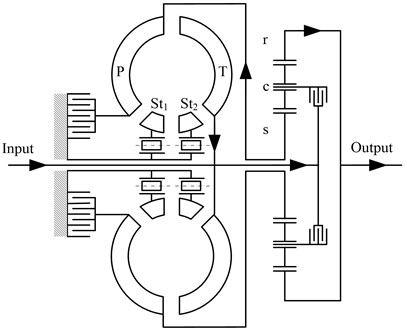
Fig. 1 shows a flow chart of a PRHTS. The major characteristic of a PRHTS involves a torque converter with a reflux power path that comprises a turbine that is connected to the input shaft of the transmission system and a pump that is connected to the sun gear of the planetary gear train. The power flow of a PRHTS is shown in Fig. 1 and is described as follows. First, the engine power reaches the input shaft of the PRHTS (as shown at the left side of Fig. 1). The power is then transferred into the carrier of the planetary gear train. Most of the power is transmitted into the ring gear (at the right side of Fig. 1), which corresponds to the power split characteristics of the planetary gear train. The remainder of the power is termed as reflux power, and it enters the pump of the torque converter via the sun gear. The reflux power enters the input shaft of the PRHTS by torque amplification of the torque converter. The reflux power combines with the output power of the engine, and the resulting combination enters the carrier. Therefore, the output shaft of the transmission system has a continuous variable speed by means of the torque converter, while the speed of the engine is constant. Therefore, PRHTS is a continuous variable transmission system.
Fig. 1Flow chart of PRHTS: T: turbine; P: pump; St1, St2: stators; r: ring gear; c: carrier; s: sun gear
3. Modeling and equations of nonlinear dynamics of PRHTS
3.1. Purely rotational nonlinear dynamic model of planetary gear train
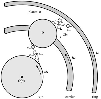
Fig. 2 contains a scheme of the purely rotational nonlinear dynamic model of the planetary gear train [26].
Newton’s law is utilized to obtain the equations of motion of the planetary gear train:
where:
Fig. 2Purely rotational nonlinear dynamic model of planetary gear train
3.2. Dynamic model of torque converter
The dynamic model of the torque converter proposed in this paper is based on four first-order differential equations [27], which are implemented in Matlab software. Eqs. (4-6) are the conservation of momentum equations of pump, turbine, and stator, respectively.
Eq. (7) is the conservation of energy equations of the torque converter:
The parameters that define the state of the models are the pump’s angular speed , turbine’s angular speed , stator’s angular speed , and volumetric flow rate . The pump torque and turbine torque were also integrated into the model.
3.3. Nonlinear dynamic model of PRHTS
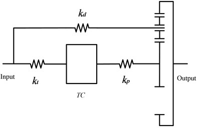
Fig. 3 illustrates a nonlinear dynamic model of the PRHTS. By merging the equilibrium equations of the planetary gear train dynamic and torque converter dynamic, the equilibrium equation of the PRHTS dynamics is established.
Fig. 3Nonlinear dynamic model of PRHTS
4. Analysis of nonlinear dynamic responses
4.1. Nonlinear dynamic responses
The possible steady motion types of a nonlinear dynamic system can be divided into four types: stationary state, periodic motion, quasi-periodic motion, and chaotic motion. The period of the periodic motion is the integral multiple of the excitation period; however, the quasi-periodic motion contains several frequencies which have no common divisor. Long-term prediction of periodic motion and quasi-periodic motion, which are insensitive to the system parameters and initial conditions, are feasible. Chaotic motion is a type of unusual steady state of motion, which has been discovered in recent years. Chaotic motion is a broadband and continuous spectrum motion, which is similar to a random motion under a single period excitation. Chaotic motion cannot be long-term predicted and is sensitive to system parameters.
Chaos signifies an apparently random irregular motion in a deterministic system; it is an important branch of nonlinear science. The Chaos theory states that there may be a simple, deterministic nonlinear law behind the complex phenomenon. From another perspective, a simple and completely determined nonlinear dynamic system can also produce a similar random irregular motion that cannot be predicted over a long period. The Chaos theory breaks the traditional determinism, and builds a bond between certainty and randomness. It also provides a new way to explain and analyze the complex phenomena in nature.
4.2. Analytical method
In this study, the nonlinear dynamics of the PRHTS, illustrated in Fig. 3, are analyzed by using bifurcation diagrams, dynamic trajectories, phase plane diagram, and Poincaré maps. The basic principles of each analytical method are reviewed in the following sub-sections.
This study creates the first analytical method to identify the onset of chaotic motion with the use of dynamic trajectories of the PRHTS. The dynamic trajectories of the PRHTS provide a fundamental indication as to whether the system behavior is periodicor non-periodic. The dynamic trajectories of chaotic motion display randomness and aperiodicity. However, it is not feasible to identify the onset of chaotic motions using them because the dynamic trajectories of quasi-periodic motion also display similar randomness and aperiodicity. Therefore, it is challenging to distinguish between quasi-periodic motion and chaotic motion with only dynamic trajectories. Accordingly, another form of analytical method is required.
Displacement and speed can indicate an object’s kinestate at any time. Therefore, displacement and speed are called state variables. Phase plane diagrams, in which - and -coordinates are displacement and speed, respectively, display the variation of state variables with time. In general, the phase plane diagram of a periodic motion is a closed curve. The phase plane diagram of a quasi-periodic motion is not a closed curve; however, it has certain regularity. The phase plane diagram of chaotic motion comprises lines of reciprocal chiasmata and twine.
In nonlinear dynamic systems, Poincaré maps are composed of state variable points of a time series corresponding to a constant time interval, which is the period of the excitation force. Poincaré maps of quasi-periodic motion comprise several closed curves. For a chaotic motion, a Poincaré map is a fractal structure comprising a number of irregularly-distributed points. Finally, for a periodic motion, a Poincaré map consists of several discrete points. Therefore, Poincaré maps are an effective analytical method to distinguish between quasi-periodic motion and chaotic motion.
Bifurcation is an important characteristic of nonlinear dynamic systems. Bifurcation represents the response of nonlinear dynamic system with varying control parameters. A bifurcation diagram summarizes the essential dynamics of nonlinear dynamic systems and is an effective method for observing its nonlinear dynamic response. Bifurcation diagrams of periodic motion consist of several curves. For a chaotic motion, a bifurcation diagram is a cloudy point set within a control parameter region. Bifurcation diagram is necessary for a comprehensive understanding of nonlinear dynamic systems. However, the use of only bifurcation diagrams is not enough to distinguish between quasi-periodic motion and chaotic motion. Accordingly, various analytical methods are required to analyze nonlinear dynamics. In this study, the bifurcation diagrams are generated using two control parameters – the internal excitation frequency, , and meshing damping ratio, , both of which are dimensionless.
4.3. Effect of dimensionless internal excitation frequency
The nonlinear dynamic equations of the PRHTS are solved using the fourth-order Runge-Kutta method. The sampled data are used to generate the bifurcation diagrams, dynamic trajectories, phase plane diagram, and Poincaré maps of the PRHTS to study its nonlinear dynamic behavior [28]. The dimensionless internal excitation frequency () of the PRHTS is one of the key parameters that affects the dynamic behavior of the mechanical transmission system. Fig. 4 presents the bifurcation characteristic of the PRHTS in terms of the dimensionless displacement, using as a bifurcation parameter. It can be observed that when the dimensionless internal excitation frequency is varied, various types of motion forms such as periodic motion, quasi-periodic motion, and chaotic motion are generated. Specifically, bifurcation diagram is a line at low values of the (< 1.13). According to the theory of bifurcation diagram, the PRHTS exhibits period-1 motion. However, when is between 1.13 and 1.25, two disjoint lines are shown in the bifurcation diagram. Therefore, the period-1motion of the PRHTS is replaced by the period-2 motion. As the value is further increased, many scattered points appear in the bifurcation diagram. Combined with Poincaré map, it can be determined that the period-2 motion turns into the quasi-periodic motion when the value is further increased from 1.25 to 1.36. Finally, for > 1.36, the PRHTS performs chaotic motion. The motion form, dynamic trajectories, phase plane diagram, and Poincaré maps at = 1.1, 1.2, 1.3, and 1.5 are presented in Figs. 5-8, respectively, to illustrate the dynamic characteristics of the system [29].
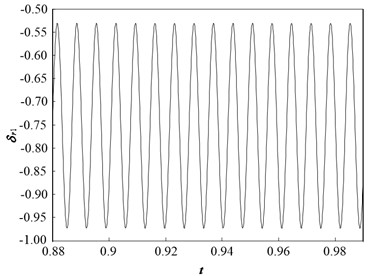
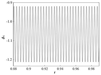
Fig. 5 presents the dynamic trajectories and phase plane diagram when is 1.1. The dynamic trajectories have the form of a sine wave, and their phase plane diagram is a closed circle. This implies that the system response is period-1 motion, which is consistent with the bifurcation diagram.
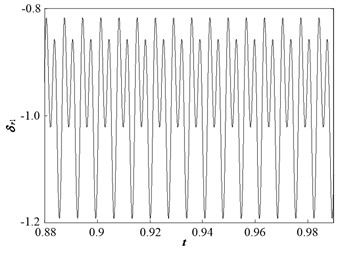
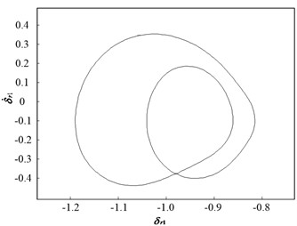
When is 1.2, the dynamic trajectories display a periodic motion, and the phase plane diagram comprises two closed circles (Fig. 6). This implies that the system motion state is transformed from periodic-1 motion to periodic-2 motion, which is consistent with the bifurcation diagram.
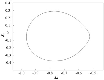
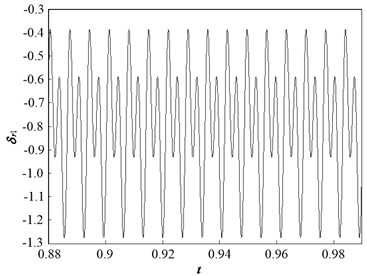
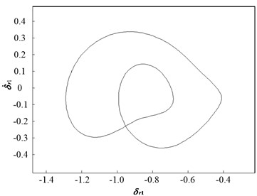
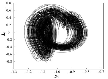
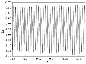
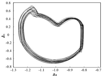
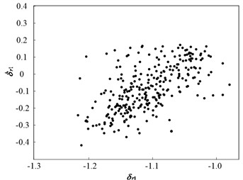
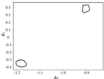
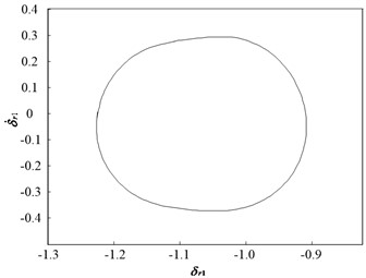
Fig. 7 and Fig. 8 present dynamic trajectories and phase plane diagrams when is 1.3 and 1.5, respectively. In Fig. 7 and Fig. 8, it can be observed that dynamic trajectories and phase plane diagrams at = 1.3 and 1.5 are similar. Accordingly, the Poincaré maps presented in Fig. 9 enable one a clear view to distinguish between the quasi-periodic motion and chaotic motion. When is 1.3, the Poincaré map comprises two closed circles, as illustrated in Fig. 9(a). When is 1.5, the Poincaré map forms a fractal structure comprising a number of irregularly distributed points, as illustrated in Fig. 9(b). Therefore, the system motion state is quasi-periodic motion when is 1.3, and chaotic motion when is 1.5.
Fig. 4Bifurcation diagram of dimensionless displacement vs. dimensionless internal excitation frequency
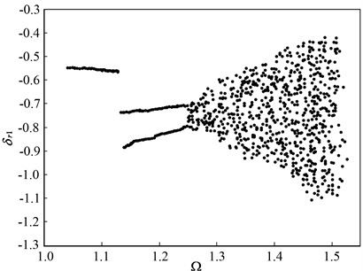
Fig. 5Dynamic characteristic curve of PRHTS at Ω = 1.1
a) Dynamic trajectories
b) Phase plane diagram
Fig. 6Dynamic characteristic curve of PRHTS at Ω = 1.2
a) Dynamic trajectories
b) Phase plane diagram
Fig. 7Dynamic characteristic curve of PRHTS at Ω = 1.3
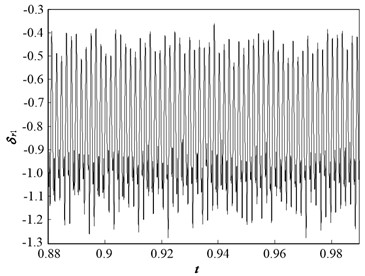
a) Dynamic trajectories
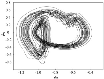
b) Phase plane diagram
Fig. 8Dynamic characteristic curve of PRHTS at Ω = 1.5
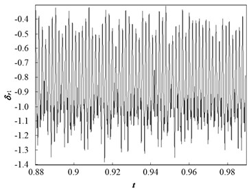
a) Dynamic trajectories
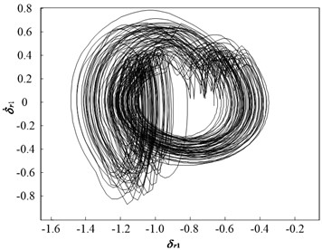
b) Phase plane diagram
Fig. 9Poincaré maps of PRHTS at Ω = 1.3 and 1.5
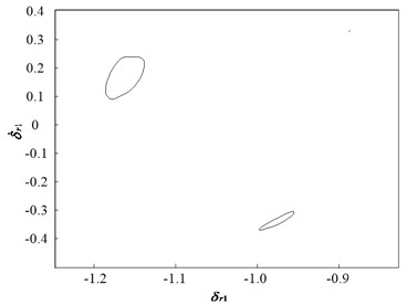
a)= 1.3
b)= 1.5
4.4. Effect of dimensionless meshing damping ratio
The dimensionless meshing damping ratio of the PRHTS is another key parameter that affects the dynamic behavior of the mechanical transmission system. Fig. 10 presents the bifurcation characteristic of the PRHTS in terms of dimensionless displacement using the dimensionless meshing damping ratio () as a bifurcation parameter. It can be observed that variation of generates various kinds of motion forms such as chaotic motion, quasi-periodic motion, and periodic motion. Specifically, it can be observed that many scattered points appear in the bifurcation diagram at low values of . Combined with Poincaré map, it can be determined that the PRHTS exhibits chaotic motion at low values of (< 0.034). However, when is between 0.034 and 0.039, the chaotic motion is replaced by quasi-periodic motion. As the value is further increased, two disjoint lines are shown in the bifurcation diagram. According to the theory of bifurcation diagram, the quasi-periodic motion of the PRHTS transits to period-2 motion when is further increased from 0.039 to 0.061. Finally, at > 0.061, bifurcation diagram is a line, so the PRHTS performs period-1 motion. The dynamic trajectories, phase plane diagram, and Poincaré maps at = 0.03, 0.035, 0.05, and 0.07 are presented in Fig. 11, Fig. 12, Fig. 14, Fig. 15, respectively, to illustrate the dynamic characteristics of the system.
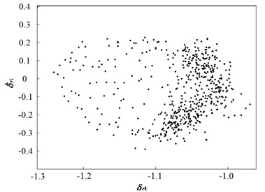
Fig. 11 and Fig. 12 present the dynamic trajectories and phase plane diagrams when is 0.03 and 0.035, respectively. In Fig. 11 and Fig. 12, it can be observed from the dynamic trajectories and phase plane diagrams at = 0.03 and 0.035 that it is challenging to distinguish between quasi-periodic motion and chaotic motion. Accordingly, Poincaré maps are illustrated in Fig. 13. When is 0.03, the Poincaré map is a fractal structure comprising a number of irregularly-distributed points, as illustrated in Fig. 13(a). When is 0.035, the Poincaré map comprises two closed circles, as illustrated in Fig. 13(b). This implies that the system motion state is chaotic when is 0.03 and quasi-periodic when is 0.035.
Fig. 14 presents the dynamic trajectories and phase plane diagram when is 0.05. The dynamic trajectories display a periodic motion, and their phase plane diagram comprises two closed circles. This implies that the system response is period-2 motion, which is consistent with the bifurcation diagram.
When is 0.07, the dynamic trajectories display a sine wave and phase plane diagram comprises a closed circle, as illustrated in Fig. 15. This implies that the system motion state is transformed from period-2to period-1 motion, which is consistent with the bifurcation diagram.
Fig. 10Bifurcation diagram of dimensionless displacement with dimensionless meshing damping ratio variation
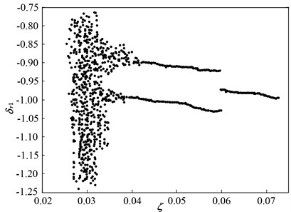
Fig. 11Dynamic characteristic curve of PRHTS at ζ = 0.03
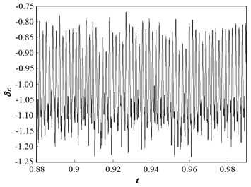
a) Dynamic trajectories
b) Phase plane diagram
Fig. 12Dynamic characteristic curve of PRHTS at ζ = 0.035
a) Dynamic trajectories
b) Phase plane diagram
Fig. 13Poincaré maps of PRHTS at ζ = 0.03 and 0.035
a)= 0.03
b)= 0.035
Fig. 14Dynamic characteristic curve of PRHTS at ζ = 0.05
a) Dynamic trajectories
b) Phase plane diagram
Fig. 15Dynamic characteristic curve of PRHTS at ζ = 0.07
a) Dynamic trajectories
b) Phase plane diagram
5. Conclusions
1) A nonlinear torsional vibration dynamic model of the PRHTS, which considers the time-varying mesh stiffness, mesh damping, and transmission error, is proposed. This study has presented a numerical analysis of the nonlinear dynamic response of the PRHTS as a function of internal excitation frequency and meshing damping ratio, both of which are dimensionless.
2) Nonlinear dynamics of the system have been analyzed with reference to its bifurcation diagrams, dynamic trajectories, phase plane diagram, and Poincaré maps. Nonlinear behaviors such as chaotic motion and quasi-periodic motion are observed, in particular, for heavy internal excitation frequency and light meshing damping ratio. It is demonstrated that an increase in the meshing damping ratio and a decrease in the internal excitation frequency lead to a decrease in the nonlinearity of the PRHTS.
3) The simulation results provide a detailed understanding of the nonlinear dynamic response of the PRHTS under various internal excitation frequencies and meshing damping ratio conditions. Specifically, the results enable the specification of internal excitation frequency and meshing damping ratio for preventing chaotic behavior, and thus for reducing the amplitude of vibrations within the system and prolonging the system life.
References
-
A. Macor and A. Rossetti, “Optimization of hydro-mechanical power split transmissions,” Mechanism and Machine Theory, Vol. 46, No. 12, pp. 1901–1919, Dec. 2011, https://doi.org/10.1016/j.mechmachtheory.2011.07.007
-
A. Rossetti and A. Macor, “Multi-objective optimization of hydro-mechanical power split transmissions,” Mechanism and Machine Theory, Vol. 62, pp. 112–128, Apr. 2013, https://doi.org/10.1016/j.mechmachtheory.2012.11.009
-
X. Zeng, N. Yang, Y. Peng, Y. Zhang, and J. Wang, “Research on energy saving control strategy of parallel hybrid loader,” Automation in Construction, Vol. 38, pp. 100–108, Mar. 2014, https://doi.org/10.1016/j.autcon.2013.11.007
-
X. Zeng et al., “Multi-factor integrated parametric design of power-split hybrid electric bus,” Journal of Cleaner Production, Vol. 115, pp. 88–100, Mar. 2016, https://doi.org/10.1016/j.jclepro.2015.07.034
-
M. A. Kluger and D. M. Long, “An overview of current automatic, manual and continuously variable transmission efficiencies and their projected future improvements,” International Congress and Exposition, Mar. 1999, https://doi.org/10.4271/1999-01-1259
-
H. Wang and D. Sun, “Theory and application on power-cycling variable transmission system,” Journal of Mechanical Design, Vol. 139, No. 2, p. 02450, Feb. 2017, https://doi.org/10.1115/1.4035055
-
H. Wang and D. Sun, “Optimal matching between a diesel engine and a PRHTS transmission,” Journal of the Brazilian Society of Mechanical Sciences and Engineering, Vol. 39, No. 9, pp. 3375–3387, Sep. 2017, https://doi.org/10.1007/s40430-017-0741-9
-
A. Kahraman and R. Singh, “Non-linear dynamics of a spur gear pair,” Journal of Sound and Vibration, Vol. 142, No. 1, pp. 49–75, Oct. 1990, https://doi.org/10.1016/0022-460x(90)90582-k
-
Y. Shen, S. Yang, and X. Liu, “Nonlinear dynamics of a spur gear pair with time-varying stiffness and backlash based on incremental harmonic balance method,” International Journal of Mechanical Sciences, Vol. 48, No. 11, pp. 1256–1263, Nov. 2006, https://doi.org/10.1016/j.ijmecsci.2006.06.003
-
J. Wang, T. C. Lim, and M. Li, “Dynamics of a hypoid gear pair considering the effects of time-varying mesh parameters and backlash nonlinearity,” Journal of Sound and Vibration, Vol. 308, No. 1-2, pp. 302–329, Nov. 2007, https://doi.org/10.1016/j.jsv.2007.07.042
-
C.-W. Chang-Jian and S.-M. Chang, “Bifurcation and chaos analysis of spur gear pair with and without nonlinear suspension,” Nonlinear Analysis: Real World Applications, Vol. 12, No. 2, pp. 979–989, Apr. 2011, https://doi.org/10.1016/j.nonrwa.2010.08.021
-
W. Kim, J. Y. Lee, and J. Chung, “Dynamic analysis for a planetary gear with time-varying pressure angles and contact ratios,” Journal of Sound and Vibration, Vol. 331, No. 4, pp. 883–901, Feb. 2012, https://doi.org/10.1016/j.jsv.2011.10.007
-
H. Gao and Y. Zhang, “Nonlinear behavior analysis of geared rotor bearing system featuring confluence transmission,” Nonlinear Dynamics, Vol. 76, No. 4, pp. 2025–2039, Jun. 2014, https://doi.org/10.1007/s11071-014-1266-8
-
Y. Guo, J. Keller, and R. G. Parker, “Nonlinear dynamics and stability of wind turbine planetary gear sets under gravity effects,” European Journal of Mechanics – A/Solids, Vol. 47, pp. 45–57, Sep. 2014, https://doi.org/10.1016/j.euromechsol.2014.02.013
-
M. Hortel and A. Škuderová, “Nonlinear time heteronymous damping in nonlinear parametric planetary systems,” Acta Mechanica, Vol. 225, No. 7, pp. 2059–2073, Jul. 2014, https://doi.org/10.1007/s00707-013-1041-9
-
S. Liu, S. Zhao, B. Niu, J. Li, and H. Li, “Stability analysis of a nonlinear electromechanical coupling transmission system with time delay feedback,” Nonlinear Dynamics, Vol. 86, No. 3, pp. 1863–1874, Nov. 2016, https://doi.org/10.1007/s11071-016-3000-1
-
M. Mohammadpour, S. Theodossiades, and H. Rahnejat, “Dynamics and efficiency of planetary gear sets for hybrid powertrains,” Proceedings of the Institution of Mechanical Engineers, Part C: Journal of Mechanical Engineering Science, Vol. 230, No. 7-8, pp. 1359–1368, Apr. 2016, https://doi.org/10.1177/0954406215590644
-
A. Saghafi and A. Farshidianfar, “An analytical study of controlling chaotic dynamics in a spur gear system,” Mechanism and Machine Theory, Vol. 96, pp. 179–191, Feb. 2016, https://doi.org/10.1016/j.mechmachtheory.2015.10.002
-
H. Zhang, S. Wu, and Z. Peng, “A nonlinear dynamic model for analysis of the combined influences of nonlinear internal excitations on the load sharing behavior of a compound planetary gear set,” Proceedings of the Institution of Mechanical Engineers, Part C: Journal of Mechanical Engineering Science, Vol. 230, No. 7-8, pp. 1048–1068, Apr. 2016, https://doi.org/10.1177/0954406215597958
-
G. Mantriota, “Theoretical and experimental study of a power split continuously variable transmission system Part 1,” Proceedings of the Institution of Mechanical Engineers, Part D: Journal of Automobile Engineering, Vol. 215, No. 7, pp. 837–850, Jul. 2001, https://doi.org/10.1243/0954407011528428
-
F. Bottiglione and G. Mantriota, “MG-IVT: an infinitely variable transmission with optimal power flows,” Journal of Mechanical Design, Vol. 130, No. 11, p. 11260, Nov. 2008, https://doi.org/10.1115/1.2976802
-
P. Linares, V. Méndez, and H. Catalán, “Design parameters for continuously variable power-split transmissions using planetaries with 3 active shafts,” Journal of Terramechanics, Vol. 47, No. 5, pp. 323–335, Oct. 2010, https://doi.org/10.1016/j.jterra.2010.04.004
-
F. Bottiglione and G. Mantriota, “Reversibility of power-split transmissions,” Journal of Mechanical Design, Vol. 133, No. 8, p. 08450, Aug. 2011, https://doi.org/10.1115/1.4004586
-
F. Bottiglione and G. Mantriota, “Effect of the ratio spread of CVU in automotive kinetic energy recovery systems,” Journal of Mechanical Design, Vol. 135, No. 6, p. 06100, Jun. 2013, https://doi.org/10.1115/1.4024121
-
K. Pettersson and P. Krus, “Design optimization of complex hydromechanical transmissions,” Journal of Mechanical Design, Vol. 135, No. 9, p. 2013, Sep. 2013, https://doi.org/10.1115/1.4024732
-
J. Lin and R. G. Parker, “Analytical characterization of the unique properties of planetary gear free vibration,” Journal of Vibration and Acoustics, Vol. 121, No. 3, pp. 316–321, Jul. 1999, https://doi.org/10.1115/1.2893982
-
D. Hrovat and W. E. Tobler, “Bond graph modeling and computer simulation of automotive torque converters,” Journal of the Franklin Institute, Vol. 319, No. 1-2, pp. 93–114, Jan. 1985, https://doi.org/10.1016/0016-0032(85)90067-5
-
M. Kostrzewski, “Sensitivity analysis of selected parameters in the order picking process simulation model, with randomly generated orders,” Entropy, Vol. 22, No. 4, p. 423, Apr. 2020, https://doi.org/10.3390/e22040423
-
Y. Chen, Y. Liao, M. Xiao, W. Zhang, and G. Jin, “Fretting wear analysis of spline couplings in agricultural tractor with axis deviation,” Journal of Vibroengineering, Vol. 22, No. 5, pp. 1165–1173, Aug. 2020, https://doi.org/10.21595/jve.2020.21304
About this article

The authors would like to acknowledge the support and contribution from the Key Laboratory of Advanced Manufacturing Technology for Automobile Parts, Chongqing University of Technology, China. The study was funded by the National Key R&D Program of China (Grant No. 2018YFB0106100), National Natural Science Foundation of China (Grant No. 52005067), Key R&D Program of Chongqing Science and Technology Major Theme Project (Grant No. cstc2018jszx-cyztzxX0005), Electric Vehicle Industry Technology Innovation Strategies Alliance Direction Common Technology Program (Grant No. CA2019), Natural Science Foundation Project of Chongqing Science and Technology Commission (Grant No.cstc2019jcyj-msxmX0733), Natural Science Foundation Project of Chongqing Science and Technology Commission (Grant No. cstc2021jcyj-msxmX0555), Youth project of Science and Technology Research Program of Chongqing Education Commission of China (No. KJQN201901115), and Initial Scientific Research Fund of Chongqing University of Technology (Grant No. 2019ZD94).
The datasets generated during and/or analyzed during the current study are available from the corresponding author on reasonable request.
The authors declare that they have no conflict of interest.
