Abstract
The present work investigates the non-smooth vibration characteristic and time delay feedback control of a gear pair system involving backlash and time-varying mesh stiffness. Firstly, a gear pair model with backlash non-smooth characteristic is established. Then in combination with the discontinuity mapping method, Floquet theory is presented to determine the stability and bifurcation of periodic response, and the period doubling bifurcation has been accurately predicted. Moreover, the maximal Lyapunov exponent is obtained to determine the chaos state in gear pair system which is conform to the bifurcation diagram and Poincare section. Finally, a time delay feedback is introduced to control the dynamic behaviors of the system, and numerical simulation results show that the system can be effectively controlled from chaotic motion into stable periodic motion by increasing the delay feedback gain or delay time.
1. Introduction
Gear transmission system plays an irreplaceable role in mechanical systems, and the vibration of gear directly affects the performance and reliability of the whole mechanical system. Therefore, it has important theoretical and practical value to study the vibration characteristic of gear system.
Given the complexity, the early researches were mainly built on the basis of linear vibration theories without considering nonlinear factors [1]. Subsequently, a kind of linear time-varying model (LTV) was established which merely contained time-varying mesh stiffness [2, 3]. As researches continue, both the time-varying meshing stiffness and backlash were considered, and the dynamic behaviors of the gear transmission system were studied from the view of time variation and non-linearity. In [4], a kind of gear pair model which contains both backlash and time-varying stiffness was established, and an approximate periodic solution was obtained through the multi-scale method. Then Yongjun Shen [5] investigate the nonlinear dynamics of a kind of gear pair model which contains backlash and time-varying mesh stiffness through incremental harmonic balance method, and the general forms of periodic solutions were given. In [6, 7], a survey of nonlinear vibration of gear transmission systems was made, the progress in nonlinear dynamics of gear transmission systems in the past twenty years was reviewed, especially nonlinear dynamic behavior of the gear system considering the backlash and time-varying mesh stiffness of teeth.
As mentioned above, a mass of valuable researches had been carried out on gear system. But they rarely involved the non-smooth dynamics of gear system. Exactly speaking, the gear system is a typical system with piecewise properties, which causes by the presence of backlash[8-13]. Due to this nonlinear factor, the gear system is no longer a smooth system, and the traditional nonlinear analysis method is no longer applicable. During recent years, considerable interest in such systems has been seen, particularly applied to piecewise linear systems excited by external periodic force[14-19]. In Ref [20], a kind of spur gear pair model including the backlash nonlinearity was established, and forced vibration responses of the gear system were investigated through multiple scale method. In Ref. [21], a nonlinear dynamic model of a spur gear pair with backlash, time-varying stiffness and static transmission error was established and based on the Melnikov analysis the global homoclinic bifurcation and transition to chaos in this model were predicted. In Ref. [22], a practical model of gear system had been proposed, and non-feedback control method was used to control chaos by applying an additional excitation torque to the driver gear. In Ref. [23], A two-degree-of-freedom system with a clearance and subjected to harmonic excitation was considered, and two key parameters of the system, the exciting frequency and clearance, were emphasized to reveal the influenced of the main factors on dynamic performance of the system. At present, the analytical methods about non-smooth dynamical systems are relatively limited, and there are few researches about the control method of systems with non-smooth characteristic.
Based on the researches above, the present paper is to investigate the non-smooth vibration characteristic and time delay control of gear pair system. Firstly, the gear pair model involving backlash, time-varying stiffness and static transmission error is established. Then the stability and bifurcation of periodic response is analyzed by the discontinuity mapping method and Floquet theory. The maximal Lyapunov exponent and several numerical methods are present to analyze the global dynamics of gear pair system. At last, a time delay feedback is introduced to control the dynamic behaviors of the system and some numerical simulations are presented to validate the control effect. These provide a theoretical basis for design and control of the gear transmission system which is widely used in practical engineering.
2. The non-smooth gear pair system dynamic model with backlash
The mechanical model of gear pair system involving backlash, time-varying meshing stiffness and static transmission error is shown in Fig. 1.
Fig. 1The non-smooth dynamic model
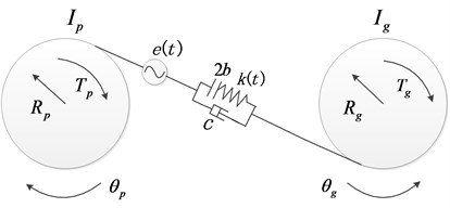
According to the Newton’s law, the balance equation for the driving wheel and driven wheel can be obtained as follows:
where and are the rotational inertia of drive and driven gears, and represent the angular displacement of drive and driven gears, and are the base radius of drive and driven gears, and represent the input torque and load torque, is the time-varying meshing stiffness, is the associated linear damping which neglected its nonlinear properties [20, 24], is the static transmission error caused by manufacturing.
In order to investigate the rotational vibration of the gear pair system, let , then Eq. (1) and Eq. (2) can be transformed as:
with , , and:
where represents the total backlash of gear pair model.
For gear pair system, both the stiffness and the static transmission error quantities can approximately be considered as time-periodic functions. In addition, if the tooth to tooth variation are neglected, the fundamental frequency of both of these quantities equals the gear meshing frequency, which implies that the meshing stiffness and static transmission error are expanded by Fourier series only up to the first harmonic term as: .
Next, introduce the parameters as: , , , , , . Then the original equation of motion Eq. (3) can eventually be put in a normalized form:
In Eq. (4), the symbol has been replaced by for simplicity, where, , , and:
Let , , , Eq. (4) can be expressed as:
where:
Eq. (5) is the dynamical state equation of the non-smooth gear pair system involving backlash, time-varying meshing stiffness and static transmission error. Next, we consider external forces as the main parameter to analysis dynamic behaviors of the system.
3. Stability analysis of periodic solutions
Since the gear pair system belongs to non-smooth system. The general method can’t deal with it thoroughly. Therefore, in combination with the discontinuity mapping method, Floquet theory is presented to analyze the stability of periodic solutions in non-smooth system.
The stability of periodic solutions is governed by the modulus of the largest eigenvalue of the monodromy matrix [25], which is the fundamental solution matrix after the period time. The monodromy matrix relates how an infinitely small perturbation of an initial point on the periodic solution causes a final disturbance of the end-point of the periodic solution:
The monodromy matrix is obtained by integrating the variational equation (a matrix differential equation):
where, is the periodic solution, is the initial value.
However, the vector field of the non-smooth system Eq. (5) is discontinuous on the boundary , the crossing of the switching boundary by the solution at time instance causes the fundamental solution matrix to jump, which we describe by a saltation matrix:
where, is called saltation matrix [26], and in some literatures is also called the discontinuity mapping. The derivation of is as follows:
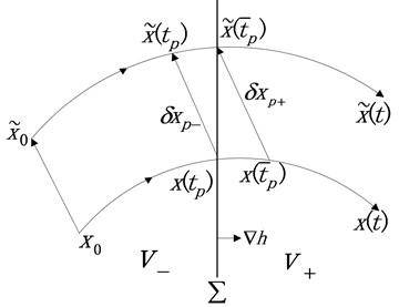
Take a trajectory such as the one depicted in Fig. 2 and suppose that it intersects the separation boundary at some time , and at time , the disturbed trajectory reaches the separation boundary . represents the initial disturbance, denotes the disturbance when the trajectory reaches the switching manifold, represents the disturbance when the trajectory reaches the separation boundary. Then, suppose , where denotes the correction when the trajectory crosses the separation boundary from sub-domain to .
Fig. 2The discontinuity mapping
In the form of Taylor series, can be expressed as:
where . According to the analytical conditions at switching point , we can get:
Form Eq. (9) and Eq. (10), we can get:
Then we can yield:
where, are the right-hand sides before and after crossing the switching boundary , is the normal to .
Based on the above analysis, the Floquet theory is introduced. According to Floquet theory, when the modulus of all the eigenvalues of are less than 1 (or all the eigenvalues of are within the unit circle) the system will be in stable periodic motion; when the modulus of any eigenvalue of is greater than 1 (or any eigenvalue of crosses the unit circle) the system will lose its stability.
The system parameters are chosen as: 0.024, 0.06, 0.61, 0.25.
The change of the modulus of the largest eigenvalue and the evolution of all the eigenvalues are shown in Fig. 3.
Fig. 3The change of the eigenvalues
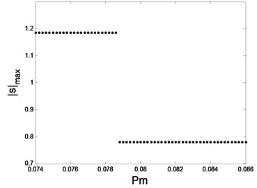
a) The change of the largest eigenvalue

b) The evolution of the eigenvalues
As shown in Fig.3, when 0.079, is less than 1, and all the eigenvalues are within the unit circle, so the system is in stable single periodic motion and the periodic solution is stable. When 0.079, is greater than 1, one of the eigenvalues jumps out the unit circle from –1, and the other one is still inside the unit circle, which implies the period doubling bifurcation occurs.
4. Global dynamics analysis of gear pair system
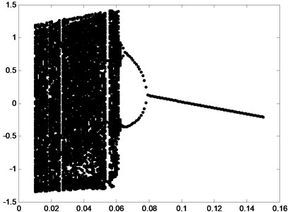
In order to demonstrate the global dynamic of gear system Eq. (5) and verify the conclusion above, the bifurcation diagram with the parameter varying is shown in Fig. 4.
In the bifurcation diagram, when is in the interval [0.08, 0.15], the response is period-1 motion. When is in the vicinity of 0.079, the period doubling bifurcation occurs. Then the system may enter chaos state through period doubling bifurcation, which are consistent with the Floquet method above.
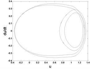
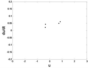
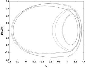
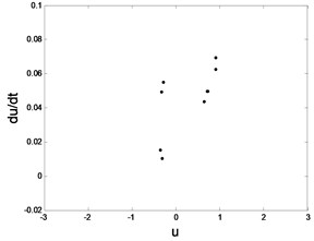
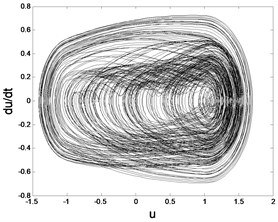
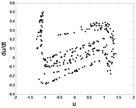
In order to demonstrate the transition process in detail, suppose 0.08, 0.07, 0.064, 0.0624, 0.05 respectively. The corresponding phase diagram and Poincare section are obtained as shown in Fig. 5.
By using the Floquet theory we can merely get the stability and bifurcation of periodic motions. For determining the chaos state, other effective method needs to be introduced. As the Lyapunov exponent spectrum is one of the most precise tools to determine the chaos state. Herein, the maximum Lyapunov exponent spectrum is presented in Fig. 6.
Fig. 4Bifurcation diagram
From Fig. 6, we can deduce that when 0.06, the maximum Lyapunov exponent are negative, which implies the system does not enter the chaos state. When 0.06, the maximum Lyapunov exponent are positive, which implies the system is under chaos state. By comparing the result with the bifurcation and Poincare sections, consistent conclusions can be obtained.
Through the analysis above, a conclusion can be obtained as: under different external excitation, the existence of the backlash will produce the impact of the teeth, which will affect the stability of the gear transmission system. Specifically, with the decrease of external excitation, the system undergoes the period doubling bifurcation and finally enters chaos state.
5. Time delay feedback control of gear pair system with backlash non-smooth characteristic
According to the dynamic analysis of gear pair system above, it can be known that the periodic- and chaotic motion will appeared under the external excitation. In order to control the dynamic behaviors of the non-smooth system, a time delay feedback is introduced in this section.
The form of time delay feedback controller can be written as follows:
where, is feedback gain and is time-delay. When , is equal to which indicates this perturbation does not change the structure of the original system.
By adding the controller given by Eq. (13) to system Eq. (4), one may obtain the following system with time-delay feedback:
When 0, 0, 0.05, other parameters remain the same. In this case, the system is under chaos state. By adjusting the feedback gain and time delay , the system can be controlled from chaotic state to desired stable state. Feedback gain and time delay are two parameters that can be controlled independently.
Fig. 5Phase trajectory (-1), Poincare map (-2) for different fav: fav= 0.08: a1) a2); fav= 0.07: b1) b2); fav= 0.064: c1) c2); fav= 0.0624: d1) d2); fav= 0.05: e1) e2)
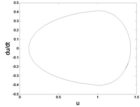
a1) Phase trajectory
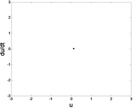
a2) Poincare map
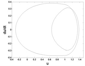
b1) Phase trajectory
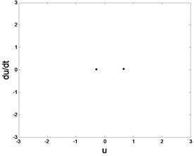
b2) Poincare map
c1) Phase trajectory
c2) Poincare map
d1) Phase trajectory
d2) Poincare map
e1) Phase trajectory
e2) Poincare map
Firstly, the control effect of the feedback gain is analyzed. To analyze the control effect of the feedback gain on the gear pair system, the parameters are selected when the system is in chaotic motion. Chose 0.05, 0.45, other parameters remain the same. Then the bifurcation diagram with the feedback gain varying is obtained as shown in Fig. 7. It can be seen in Fig. 7 that, with the increase of , the system in chaotic motion undergoes the period doubling bifurcation and it later becomes single stable periodic motion.
Fig. 6The maximum Lyapunov exponent spectrum
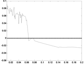
Fig. 7Bifurcation diagram of system: β is varied from 0 to 0.5
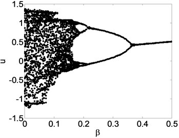
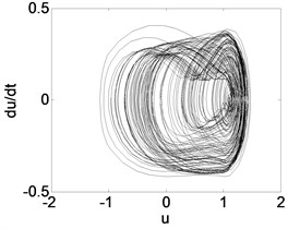
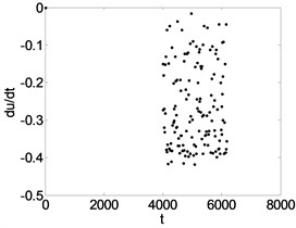
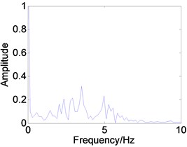
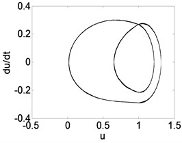
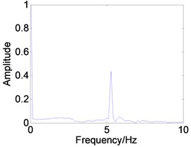
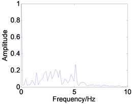
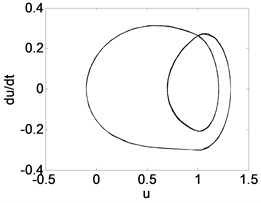
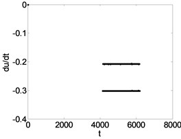
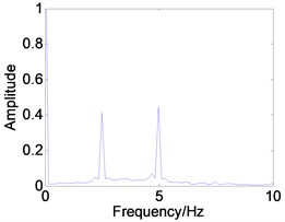
Fig. 8Phase trajectory (a1, b1, c1), Poincare map (a2, b2, c2), and power spectrum (a3, b3, c3) for different β. (a1)-(a3) β= 0.04; (b1)-(b3) β= 0.3; (c1)-(c3) β= 0.4
a1)
a2)
a3)
b1)
b2)
b3)
c1)
c2)
c3)
In order to demonstrate the transition process in detail, suppose 0.04, 0.3, 0.4 respectively. The corresponding phase diagram, Poincare section, and power spectrum are obtained as shown in Fig. 8.
Then, the control effect of the time delay is also analyzed. The parameters are selected when the system is in chaotic motion. Chose 0.05, 0.04, other parameters remain the same. Then the bifurcation diagram with the time delay varying is obtained as shown in Fig. 9. It can be seen in Fig. 9 that, with the increase of , the system in chaotic motion undergoes the period doubling bifurcation and it later becomes single stable periodic motion.
Fig. 9Bifurcation diagram of system: τ is varied from 0 to 2.5
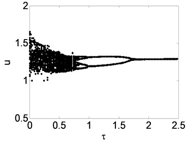
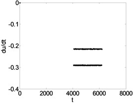
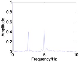
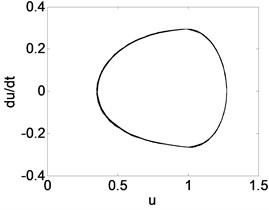
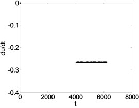
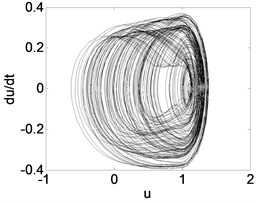
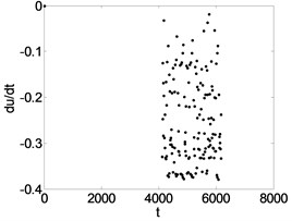
Fig. 10Phase trajectory (a1, b1, c1), Poincare map (a2, b2, c2), and power spectrum (a3, b3, c3) for different τ. (a1)-(a3) τ= 0.5; (b1)-(b3) τ= 1.2; (c1)-(c3) τ= 1.8
a1)
a2)
a3)
b1)
b2)
b3)
c1)
c2)
c3)
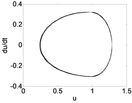
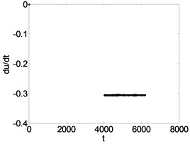
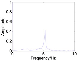
In order to demonstrate the transition process in detail, suppose 0.5, 1.2, 1.8 respectively. The corresponding phase diagram and Poincare section are obtained as shown in Fig. 10. The simulation diagrams are described as shown in Table 1. Table 1 shows that by increasing the feedback gain or time delay , the system can be effectively controlled from the chaotic state to periodic-1 motion.
Table 1Under different values of β and τ, the description of phase trajectory, Poincare section and power spectrum
Control parameters | Simulation diagrams | Description of system motion |
0.04 | Fig. 8(a1), (a2), (a3) | The system is chaotic. It can be seen that the phase trajectory repeatedly winding in enclosed area but not closed, Poincare section are irregular scattered points set, and power spectrum is continuous. |
0.5 | Fig. 10(a1), (a2), (a3) | |
0.3 | Fig. 8(b1), (b2), (b3) | The system response is a stable period-2 motion. It can be seen that the phase trajectory for two closed curves, the Poincare map for two parallel lines, and the power spectrum are two obvious peak values. |
1.2 | Fig. 10(b1), (b2), (b3) | |
0.4 | Fig. 8(c1), (c2), (c3) | The system response is a period-1 motion. It can be seen that the phase trajectory for a closed curve. the Poincare map for a straight line, and the power spectrum has an obvious peak value. |
1.8 | Fig. 10(c1), (c2), (c3) |
Through the research and realization of above control method, a conclusion can be obtained as: delay error as the control signal is fed back to the original system, and then by adjusting delay feedback gain and time delay the system can be controlled from the chaotic state to the stable periodic state. The control signal is a persistent excitation signal which can avoid the system being affected by the external environment as far as possible. This method does not need to know the accurate mode and the stable periodic orbit of the system. The result of simulation indicates the design of the controller is simple and easy to realize and it has strong adaptation.
6. Conclusions
In this paper, considering backlash, time-varying stiffness and static transmission error, the mechanical model of a gear pair system with backlash non-smooth characteristic is established according to the Newton’s law. In combination with the discontinuity mapping method, Floquet theory has been presented to determine the stability and bifurcation of periodic response, and the period doubling bifurcation has been accurately predicted which is conform to the bifurcation diagram. In addition, the maximum Lyapunov exponent spectrum has been obtained to determine the chaos state in gear pair system. By comparing it with the bifurcation diagram, phase diagram and Poincare section, consistent conclusions have been gained. Finally, a time delay feedback is introduced to control the dynamic behaviors of the system. The method uses the feedback error signal to stabilize the system to the desired orbit. Numerical simulation results show that increasing the delay feedback gain and time delay both can effectively control system from chaos to period-1 motion.
The researches in this paper can not only make us have a better understanding of the non-smooth vibration, but also provide us with an effective control method to suppress the vibration in gear transmission system. In addition, the conclusions of this work have important practical value, which can guide us to choose reasonable system parameters in the actual project to avoid the non-smooth vibration which we do not expect.
References
-
Özgüven H. N., Houser D. R. Mathematical models used in gear dynamics – a review. Journal of Sound and Vibration, Vol. 121, Issue 3, 1988, p. 383-411.
-
Vinayak H., Singh R. Multi-body dynamics and model analysis of compliant gear bodies. Journal of Sound and Vibration, Vol. 210, Issue 2, 1998, p. 171-214.
-
Vinayak H., Singh R., Padmanabhan C. Linear dynamic analysis of multi-mesh transmissions containing external, rigid gears. Journal of Sound and Vibration, Vol. 185, Issue 1, 1995, p. 1-32.
-
Theodossiades S., Natsiavas S. Non-linear dynamics of gear-pair systems with periodic stiffness and backlash. Journal of Sound and Vibration, Vol. 229, Issue 2, 2000, p. 287-310.
-
Shen Yongjun, Yang Shaopu, Liu Xiandong Nonlinear dynamics of a spur gear pair with time-varying stiffness and backlash based on incremental harmonic balance method. International Journal of Mechanical Sciences, Vol. 48, Issue 11, 2006, p. 1256-1263.
-
Wang J., Li R., Peng X. Survey of nonlinear vibration of gear transmission systems. Anesthesia and Analgesia, Vol. 56, Issue 3, 2003, p. 222-227.
-
Jianjun W., Li Q., Li Runfang, et al. Research advances for nonlinear vibration of gear transmission system. Advances in Mechanics, Vol. 35, Issue 1, 2005, p. 36-51.
-
Chen Q., Ma Y., Huang S., et al. Research on gears’ dynamic performance influenced by gear backlash based on fractal theory. Applied Surface Science, Vol. 313, Issue 1, 2014, p. 325-332.
-
Yang T., Yan S., Han Z. Nonlinear model of space manipulator joint considering time-variant stiffness and backlash. Journal of Sound and Vibration, Vol. 341, Issue 14, 2015, p. 246-259.
-
Zhang H., Shi Y., Mehr A. S. Stability and stabilization in switched discrete-time systems. International Journal of Adaptive Control and Signal Processing, Vol. 26, Issue 26, 2012, p. 991-1012.
-
Maré J.-Charles Requirement-based system-level simulation of mechanical transmissions with special consideration of friction, backlash and preload. Simulation Modelling Practice and Theory, Vol. 63, Issue 1, 2016, p. 58-82.
-
Ponce Israel U., Orlov Yury, Aguilar Luis T., et al. Nonsmooth H∞ synthesis of non-minimum-phase servo-systems with backlash. Control Engineering Practice, Vol. 46, Issue 1, 2016, p. 77-84.
-
Ding B., Cazzolato B. S., Grainger S., et al. Active preload control of a redundantly actuated Stewart platform for backlash prevention. Robotics and Computer-Integrated Manufacturing, Vol. 32, Issue 1, 2015, p. 11-24.
-
Kurushin M. I., Balyakin V. B., Kurushin S. А. Methods of vibration control in elastic systems with gears. Procedia Engineering, Vol. 106, 2015, p. 192-201.
-
Chávez J. P., Wiercigroch M. Bifurcation analysis of periodic orbits of a non-smooth Jeffcott rotor model. Communications in Nonlinear Science and Numerical Simulation, Vol. 18, Issue 9, 2013, p. 2571-2580.
-
Zhang C., Han X., Bi Q. Dynamical behaviors of the periodic parameter-switching system. Nonlinear Dynamics, Vol. 73, Issues 1-2, 2013, p. 29-37.
-
Hu Z., Tang J., Chen S., et al. Coupled translation-rotation vibration and dynamic analysis of face geared rotor system. Journal of Sound and Vibration, Vol. 351, 2015, p. 282-298.
-
Huang J., Shi Y., Zhang X. Active fault tolerant control systems by the semi-Markov model approach. International Journal of Adaptive Control and Signal Processing, Vol. 28, Issue 9, 2014, p. 833-847.
-
Vörös J. Identification of nonlinear dynamic systems with input saturation and output backlash using three-block cascade models. Journal of the Franklin Institute, Vol. 351, Issue 12, 2014, p. 5455-5466.
-
Moradi H., Salarieh H. Analysis of nonlinear oscillations in spur gear pairs with approximated modelling of backlash nonlinearity. Mechanism and Machine Theory, Vol. 51, Issue 5, 2012, p. 14-31.
-
Farshidianfar A., Saghafi A. Identification and control of chaos in nonlinear gear dynamic systems using Melnikov analysis. Physics Letters A, Vol. 378, Issue 46, 2014, p. 3457-3463.
-
Saghafi A., Farshidianfar A. An analytical study of controlling chaotic dynamics in a spur gear system. Mechanism and Machine Theory, Vol. 96, 2016, p. 179-191.
-
Luo G. W., Shi Y. Q., Jiang C. X., et al. Vibro-impact dynamics of a two-degree-of freedom periodically-forced system with a clearance: diversity and parameter matching of periodic-impact motions. International Journal of Non-Linear Mechanics, Vol. 65, Issue 4, 2014, p. 173-195.
-
Wang J., Zheng J., Yang A. An analytical study of bifurcation and chaos in a spur gear pair with sliding friction. Procedia Engineering, Vol. 31, Issue 16, 2012, p. 563-570.
-
Leine R. I., Campen D. H. V. Bifurcation phenomena in non-smooth dynamical systems. European Journal of Mechanics – A/Solids, Vol. 25, Issue 4, 2006, p. 595-616.
-
Leine R. I. Bifurcations in Discontinuous Mechanical Systems of Filippov-Type. Eindhoven University of Technology, 2000.
Cited by
About this article

Project supported by the National Natural Science Foundation of China (Grant Nos. 51575472, 61673334). Talent Project of Human Resources Department of Hebei Province (Grant No. A201500109).
