Abstract
Brushless DC motor (BLDCM) is a multivariable nonlinear time-varying system, which is difficult to control. The discrete sliding mode control method for BLDCM of electric vehicle on the basis of particle swarm optimization (PSO) is studied to improve the application of BLDCM in electric vehicle. The mathematical model of BLDCM of electric vehicle is established using the state formula. Based on the mathematical model of BLDCM, through the analysis of electromagnetic torque control of BLDCM, it is clear that controlling the angle between rotor flux and stator flux can accurately control the electromagnetic torque of BLDCM. The adaptive discrete sliding mode controller (SMC) is set to control the electromagnetic torque of BLDCM of electric vehicle, and the PSO algorithm is adopted to obtain the optimal parameters of the adaptive discrete SMC to realize the discrete sliding mode control of BLDCM of electric vehicle. According to experimental results, the proposed method can achieve the accurate control of torque and speed of BLDCM of electric vehicle, and increase the application of BLDCM in electric vehicle.
Highlights
- An adaptive discrete SMC electromagnetic torque control system is studied and designed
- Using Particle Swarm Optimization to Calculate the Optimal Parameters of Sliding Mode
- The mathematical model of brushless DC motor is established
- Research has weakened the chattering phenomenon of SMC
- The research has improved the motor control accuracy and anti-interference ability
1. Introduction
Nowadays, under the dual pressure of energy shortage and environmental degradation, vigorously developing electric vehicles and promoting the sustainable development of automobile industry has become the common goal of the development of automobile industry all over the world. Major automobile enterprises and colleges and universities are actively studying and developing electric vehicles and related technologies. Wide application of BLDCM of electric vehicle has been achieved in household appliances, automobile and other industries because of its small size and good reliability [1]. Compared with other motors, the speed regulation control system of BLDCM of electric vehicle is a multivariable and strongly coupled complex system. It is difficult for the classical PID controller to set the parameters in the speed regulation control process of BLDCM of electric vehicle [2], and it is also difficult to achieve the ideal results. Driving motor is the heart of electric vehicle, so driving motor control technology is also particularly important for electric vehicle. The principle of electric vehicle motor control technology is to efficiently transform the electric energy of power battery into the mechanical energy, overcome various resistance in the operation of electric vehicle [3], transform the kinetic energy into the electric energy and recover it to the energy storage system in the case of electric vehicle braking to realize the mutual conversion of energy. The control efficiency of the drive system directly affects the power performance and economic performance of electric vehicles [4], so the research of drive motor control technology is of great significance. In daily life, electric vehicles often encounter driving conditions such as frequent starting, acceleration and deceleration, climbing and braking. Therefore, the driving motor is different from the general motor. The particularity of electric vehicle operation requires that it can meet various complex working conditions encountered by the vehicle during driving [5].Generally speaking, the driving motor of electric vehicle should meet the following requirements: large starting torque, good starting performance and fast torque response; In the low-speed constant torque area, there should be a large torque, while in the high-speed constant power area, it is necessary to maintain a high speed; High impact resistance and reliability, able to work for a long time in harsh environment; The volume and mass should not be too large to relieve the weight of electric vehicle and improve the power performance of the vehicle. The structure of DC motor is simple, the control method has been very mature, and has good speed regulation performance [6], which can basically meet the performance requirements of vehicles. Therefore, when electric vehicles were just developed, most of the driving motors of electric vehicles were DC motors. However, the brush and commutator in the DC motor may cause commutation sparks during motor operation, resulting in rotor heating, electromagnetic interference and impact on other electrical appliances in the vehicle. Due to the mechanical structure of DC motor, if it works for a long time, the internal structure of the motor is easy to be lost, which will increase the maintenance cost, limit the instantaneous overload capacity and motor speed. Besides, it will also be difficult to meet the requirements of modern electric vehicles [7]. Therefore, DC motor is rarely used as the driving motor of electric vehicles at present. Permanent magnet BLDCM is improved and developed from ordinary DC motor. Electronic commutation device is used instead of mechanical commutation, so there is no commutation spark and it is easy to dissipate heat. Permanent magnet BLDCM has simple mechanical structure, large starting torque, small scale, high-level efficiency and convenient maintenance [8]. Due to the high power and density of the electric motor, it can reduce the electric motor’s size and density effectively. SMC is a control strategy of variable structure control system [9]. The control characteristic has nothing to do with the parameters and disturbance input of the system. It can make the system have good robustness and is widely used.
At present, there are many researches on the discrete SMC of BLDCM of electric vehicle. Curiel-Olivares et al. studied the active disturbance rejection controller (ADRC) for the balance problem of electric vehicle [10]. This method can effectively improve the balance problem of electric vehicle, but there is a defect that the calculation process is too complex; Aiming at the dynamic performance of BLDCM driver, Ebadpour et al. researched fast fault-tolerant control (FFTC) to improve the control performance of BLDCM. This method can achieve the control of BLDCM, but the control performance is not ideal [11]; Zheng et al. proposed the improved DC link series IGBT chopper strategy for BLDCM drive [12], realized the driving performance of BLDCM, and used this method to control BLDCM, which has chattering. Aiming at the defects of the above control methods, the discrete SMC method of BLDCM of electric vehicle on the basis of PSO is proposed in this study. The mathematical model of Brushless DC motor of electric vehicle is established by using state equation. On the basis of the mathematical model of Brushless DC motor, through the analysis of the electromagnetic torque control of Brushless DC motor, it is shown that the electromagnetic torque of Brushless DC motor can be accurately controlled by controlling the angle between the rotor flux and the stator flux. The adaptive discrete sliding mode controller (SMC) is used to control the electromagnetic torque of the brushless DC motor of electric vehicles, and the particle swarm optimization algorithm is used to obtain the optimal parameters of the adaptive discrete sliding mode controller, so as to achieve efficient control of the brushless DC motor of electric vehicles. The experimental results show that the method applied to the BLDCM of electric vehicle can achieve the effective control of BLDCM of electric vehicle, and the control performance is superior.
It can be seen that in the research of related fields, more research focuses on the dynamic performance and control effectiveness of brushless DC motor. However, this study focuses on the dynamic and static control performance of the control strategy, and at the same time focuses on the design of the anti-interference of the system, so that the model can achieve more stable control effect that is less susceptible to interference on the basis of dynamic and static efficient control, and provide technical support for practical applications in complex environments.
2. Materials and methods
2.1. Mathematical model of BLDCM of electric vehicle
The composition structure of BLDCM includes motor body, electronic switch circuit and position sensor connected with rotor shaft. The motor body includes rotor and stator. The AW (AW) which is installed on the stator is generally made into polyphase. The windings can be connected in star or triangle, which are respectively connected with each power tube of the electronic switching circuit. The rotor is made of permanent magnet material, which can be made into multiple pairs of magnetic poles [13]. The mathematical model of electric vehicle’s BLDCM is established using the state formula. The three-phase voltage formula of BLDCM of electric vehicle is shown in Eq. (1):
where, the stator phase winding; , is the self-inductance of stator, is the mutual inductance of stator phase winding; , , is the current of phase , and respectively; , , is the reverse electromotive force of phase , and respectively.
The calculation formula for the opposite electromotive force of BLDCM of electric vehicle is shown below:
where is the angular velocity of rotor; is the angle of rotor; is the back EMF shape function of phase .
With the dynamic change of , and are the back EMF shape functions of phase and respectively. The shape of the three-phase back EMF shape function is mainly the same, and the difference of phase is 120° electrical angle. The specific values of the three shape functions depend on the actual motor back EMF.
The expression of electromagnetic torque of BLDCM of electric vehicle is shown below:
where, is electromagnetic power; is the motor’s poles; is electromagnetic torque.
To form a complete mathematical model of BLDCM of electric vehicle, the motion formula of BLDCM of electric vehicle is introduced here, and the expression is shown below:
where, is the torque of load; is the inertia moment; is the coefficient of friction.
In modern control theory, the research of the control system motion state is mainly realized by its state formula. The state formula of BLDCM of electric vehicle can be obtained by algebraic transformation of differential formula mathematical model [14]. In this paper, the angular velocity and three-phase current are selected as state variables to obtain the fourth-order state formula, which is expressed as:
where:
and is the maximum value of permanent magnet flux distribution of turn chain of each phase winding; .
The controllability of linear system is the basis of optimal control and optimal estimation. For the state formula of BLDCM of electric vehicle, it is necessary to test its controllability [15]. The controllability matrix expression of BLDCM of electric vehicle is shown below:
where, , , 1, 2, 3.
It can be seen from the above formula that the controllable matrix satisfies 4 at any time. According to the rank criterion of linear time-varying system, the mathematical model of BLDCM of electric vehicle represented by Eq. (6) is completely controllable.
2.2. Control of electromagnetic torque of BLDCM
According to the unified theory of BLDCM of electric vehicle, the expression of electromagnetic torque of motor is shown below:
where: is the torque coefficient; and are rotor flux amplitude and stator flux amplitude respectively; is the included angle between rotor flux and stator flux.
Suppose that the inner circle radius of the hexagonal flux path of the BLDCM of the electric vehicle is , the motion speed is , the rotor flux rotates counterclockwise, the stator flux is located in the sector, and the initial position is at point .
The amplitude expression of stator flux linkage (SFL) is shown below:
where, .
In the case that SFL moves to point , the absolute value of the amplitude change rate of the SFL is the largest. From Eq. (8), it can obtain:
The sine value of the included angle between rotor flux and stator flux is:
where: is the initial value of the angle between rotor flux and stator flux; and are the rotation speed of rotor flux and stator flux respectively.
The angle of SFL is shown below:
When the SFL moves to point , the absolute value of is the smallest. From Eq. (11):
Ignoring that and are close to 1, we can get from Eq. (12):
Generally, if , can be obtained.
The above analysis shows that the change of electromagnetic torque mainly depends on the included angle between rotor flux and stator flux. Controlling the angle between rotor flux and stator flux can control the electromagnetic torque of BLDCM.
After combining the given torque of the BLDCM with the given torque vector comparator, the output of the BLDCM is directly controlled by the difference value of the given torque vector comparator [16]. During low-speed commutation, the attenuation of closed commutation current is slower than that of open commutation current. At this time, the direct torque control can chop the open commutation current by selecting the corresponding voltage space vector (VSV) to keep the non-commutation current constant and suppress the electromagnetic torque ripple of current commutation. At high speed, the attenuation of closed commutation current is faster than that of open commutation current. At this time, direct torque control loses the ability to suppress current commutation electromagnetic torque ripple.
2.3. Discrete SMC
Through the above analysis, it can be seen that controlling the angle between rotor flux and stator flux can achieve the control of electromagnetic torque of BLDCM. The discrete SMC is set to control the electromagnetic torque of BLDCM of electric vehicle. The switching function expression of adaptive discrete SMC is shown below:
where, represents the adjustment function, and represent the stator flux signal and rotor flux signal respectively.
Using exponential reaching law control, we can get:
where, represents the rate of approaching the switching surface; represents the calculation step; represents the switching function.
Under the condition of exponential approach rate, the control voltage expression of BLDCM of electric vehicle is shown below:
The following is the stability proof, and the Lyapunov function is selected:
If the BLDCM of electric vehicle is required to be stable, it shall meet , and the stability condition of discrete sliding mode is equivalent to:
It can get:
It can be seen from Eq. (19) that when exponential reaching law is adopted. To meet the stable operation of BLDCM of electric vehicle, it is necessary to meet:
In sliding mode control, due to the influence of input control switching, it is difficult for the system to reach the equilibrium state after reaching the sliding mode surface, so it often forms the phenomenon of repeatedly crossing the sliding mode surface, forming chattering. This study has optimized this phenomenon. According to Eq. (20), when the value of is large, the sign of changes continuously near , resulting in strong chattering of the system; When the value of is small, changes slowly and the arrival time will be prolonged. Therefore, in the initial stage, the value of should be large and quickly reach near the sliding surface [17], and then it should be gradually reduced to weaken the chattering phenomenon of the system, taking:
where is a constant value. By changing the size of , the speed of the system approaching the sliding mode surface can be adjusted. In the discrete SMC, the selection of exponential approach rate needs to meet the conditions required by Eq. (20). Therefore, whether the discrete SMC is stable depends on the influence of [18], and . By introducing Eq. (21) into Eq. (20), it can be deduced that the stability of discrete SMC needs to meet:
By introducing Eq. (22) into Eq. (16), we can get:
Whether the discrete SMC is stable is analyzed. Based on the above formula, it can see that:
Therefore, under the condition of satisfying Eq. (22), the system is stable. At this time, is in the range of (0, 0.2]. Under the condition of satisfying Eq. (22), the value of is not the smaller the better. Due to the existence of nonlinear friction, appropriately increasing the value of can keep the system in small amplitude chattering, which improves the rapidity of the system and weakens the impact of low-speed area caused by friction, but should not be too large, which will enhance the chattering of the system.
2.4. PSO algorithm
PSO algorithm is a smart optimization algorithm on the basis of group cooperation. It is a random search algorithm developed from the simulation of birds’ foraging behavior. PSO algorithm has the strengths including evolutionary computing and swarm intelligence. The global search is carried out by the cooperation and competition of PSO. The reason why PSO algorithm is selected as the main optimization algorithm in this study is that compared with genetic algorithm and simulated annealing algorithm, PSO algorithm is more efficient in improving step wave response ability. In the environment of brushless DC motor, PSO algorithm has greater advantages in speed control, overshoot control, etc. Firstly, a group of initial particles are randomly generated. Each particle in flight is a feasible solution, and the basis of judgment is determined by the fitness function. Each particle has a velocity in solution space, which determines its flying direction and distance. Particles generally follow the track of the present best particle and obtain the best solution through generation based on generation search. In all generations of particle swarm, particles will be subject to two extreme values. One is the optimum solution sought by the particle itself from the beginning to the end, and the other is the overall best solution sought by the whole particle swarm from the beginning to the end [19].
In an -dimensional space, the population number is , is the speed of the -th particle at the -th iteration update, is the position vector of the -th particle at the -th iteration update, and is the optimal position of the particle in the -th iteration before the -th particle, namely, the position of the individual extreme value. is the optimal position of the whole particle swarm in the first -th iterations, that is, the position of the extreme value of the population. The particle swarm, at the beginning, is initialized as a group of random particles, and then looks for and follows the current best particle in the solution space. Each particle updates itself in the iteration by following the best solution value of the present particle itself and the best solution value experienced by the whole group. The formula of position and particle velocity in solution space is shown below:; .
Among it, and are learning factors, and is the random number in [0, 1].
The basic PSO algorithm is relatively plain and easy to realize. It has strengths including strong local search ability and fast calculation speed, and it also has less parameters. Nevertheless, during operation, PSO has strong local convergence. Thus, all things will be ignored and it is easy to fall into local best solution. Aiming at the deficiency of basic PSO algorithm, inertia weight is added to the speed term. Inertia weight indicates the particle update speed ability, which has a great influence on whole algorithm’s accuracy and convergence. The velocity and position formula of particle swarm with inertia weight is shown below:
The larger value of can enhance the algorithm’s global search ability. However, a smaller can enhance the algorithm’s local search ability. Therefore, in the iterative process, value should be reduced to make the particles achieve a balance between their convergence speed and search ability. value is determined according to the following formula:
where, indicates the initial weight, indicates the final weight, indicates the current number of iterations of the particle, and indicates the maximum number of iterations of the particle.
Under sliding mode control, the neural synovial control law under PSO control is shown in Eq. (27):
where, represents the output value of BP neural network, which is taken as the switching coefficient of control input. When is used, the control law is the traditional equivalent sliding mode control rate. When is used, the chattering phenomenon can be controlled by using the output of BP neural network. When does not use fixed constants, but uses variable constants, when the absolute value of error is not less than 0.03, a larger parameter setting value can effectively reduce the transition time and improve the reaction speed. When is about to reach the sliding surface, a small parameter setting can effectively reduce the buffeting phenomenon. The parameter setting value can be confirmed by Eq. (28):
The BP neural network process used in the study is:
1) Initialize the threshold value and weight value.
2) Given input and target output.
3) Calculate the actual output and calculate the error output layer error.
4) The threshold and weight are corrected according to the error back propagation.
5) Output the results when the error accuracy and cycle number requirements are met, otherwise return to step (3).
Discrete SMC of PSO algorithm
Let be the calculation step; refers to the number of calculated points. Discrete SMC of BLDCM of electric vehicle on the basis of PSO algorithm is shown below:
Eq. (7) is discretized to obtain the difference formula as follows:
Let the total number of particles be . For each particle , its corresponding objective function value can be defined as and recorded as:
It can be seen from Eq. (31) that during optimization, the particles are scattered on the division points according to the random principle, and the particles with the best evaluation function value are recorded [20]. In the search process, the neighborhood search mechanism is embedded, that is, when , particle moves from its neighborhood to particle's neighborhood according to probability ; When , particle searches its own neighborhood to find a better solution.
3. Results
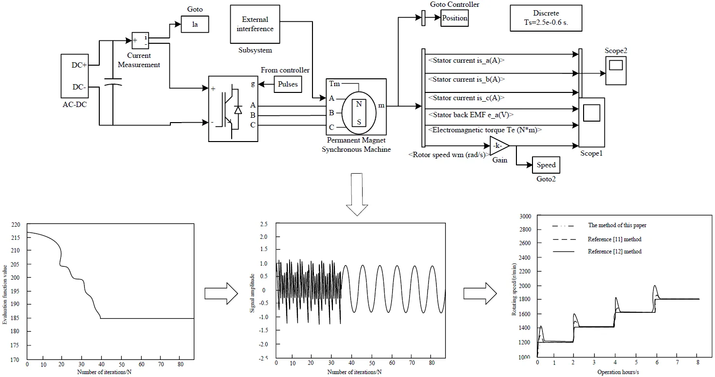
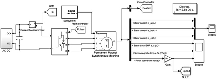
To verify the effectiveness of discrete SMC method for BLDCM of electric vehicle on the basis of PSO to control BLDCM of electric vehicle, an experimental model of BLDCM control of electric vehicle is built in Simulink software. The parameters of Brushless DC motor of electric vehicle are set as follows: rated power: 1.5 kW, rated voltage: 190 V, rated current: 50 A, rated speed: 2800 R/min, stator resistance: 0.785 Ω, stator inductance: 1.5 MH, voltage constant: 0.1455 v/(r.min-1), torque constant: 1.4 N.M, moment of inertia: 0.009 kg. M2, resistance factor: 0.002, number of poles of Brushless DC motor: 5. The step signal of BLDCM of electric vehicle is set as 1. The discrete SMC control system model of Brushless DC motor for electric vehicles is shown in Figure 1.
Fig. 1Discrete SMC control system model of Brushless DC motor of electric vehicle
The state change curve of BLDCM of electric vehicle controlled by the proposed method is shown in Fig. 2.
Fig. 2System state change curve
According to the experimental results in Fig. 1, when the number of iterations is 40, the PSO algorithm can stabilize the discrete SMC of BLDCM of electric vehicle in a fixed control range. The experimental results in Fig. 2 verify that the proposed method has ideal discrete SMC performance of BLDCM of electric vehicle, and can quickly stabilize the BLDCM of electric vehicle to the ideal control range with less iterations.
In this paper, PSO algorithm is used to realize the discrete SMC of BLDCM of electric vehicle. The evolution curve of evaluation function of PSO algorithm is shown in Fig. 3.
Fig. 3Evaluation function evolution curve
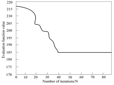
According to experimental results in Fig. 2, with the increase of the number of iterations of the PSO algorithm, the evaluation function value of the PSO algorithm continues to decrease until the number of iterations is 40, and the evaluation function value of the PSO algorithm is stable at 185. At this time, the evaluation function value is the final evaluation function value of the BLDCM of electric vehicle controlled by the PSO algorithm in this method. The experimental results in Fig. 3 verify that the PSO algorithm adopted in this method can achieve the effective control of BLDCM of electric vehicle.
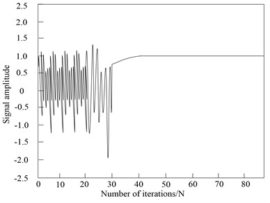
The discrete SMC of BLDCM of electric vehicle is realized using the proposed method, and the sinusoidal signal is applied to the discrete SMC. The output result of the control signal is shown in Fig. 4.
Fig. 4Sine signal control effect
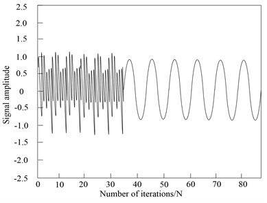
According to the experimental results in Fig. 4, the sinusoidal signal frequency set for the BLDCM of electric vehicle is high, and the signal of BLDCM of electric vehicle changes rapidly, which improves the difficulty of discrete SMC of electric vehicle’s BLDCM of. The proposed method can still track the sinusoidal signal of discrete SMC of electric vehicle’s BLDCM of smoothly, with good control performance, without jitter and vibration. At the same time, the tracking waveform of BLDCM of electric vehicle controlled by this method has no distortion, which verifies that this method has good control performance.
According to the statistics, the proposed method is adopted to control the BLDCM of electric vehicle, start the BLDCM of electric vehicle without load, give the initial speed of 1600 r/min, adjust the speed to 1900 r/min after 100 ms after the speed is stable, and obtain the corresponding speed and torque response curve of BLDCM of electric vehicle, as shown in Fig. 5.
Fig. 5Response curve of speed and torque of BLDCM of electric vehicle
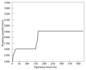
a) Speed curve
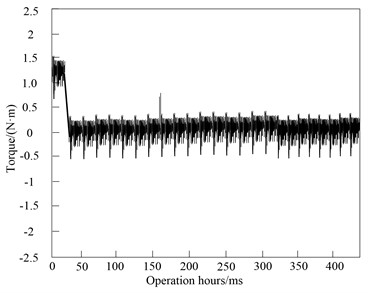
b) Torque curve
By comprehensively analyzing the experimental results in Fig. 5 and Fig. 6 and observing the speed response curve in Fig. 5(a), the no-load starting response curve of BLDCM of electric vehicle quickly rises to the reference speed and stabilizes quickly, and the response time is less than 50 ms. When the operation time of BLDCM of electric vehicle is 150 ms, it can adjust the speed of BLDCM of electric vehicle to 1900 r/min, and the BLDCM of electric vehicle rises to the given speed in a very short time. This method controls the BLDCM of electric vehicle with short rise time and basically no overshoot. Therefore, it can be seen that the system can operate stably when the speed demand changes, the steady-state error is controlled within 0.1 %, and the adjustment time is short. The speed regulation effect is good. The motor only needs to overcome friction during no-load starting, so the torque response curve has a torque of about 1.5 nm at the starting point of the motor, and then quickly drops to 0. At this time, the motor starts to operate stably. When the time is 150 ms, adjust the speed, the torque increases rapidly, and then quickly recover to the original state. The BLDCM of electric vehicle also operates stably at the new speed. The current waveform shows the current fluctuation of BLDCM of electric vehicle at the beginning of starting and at the moment of speed change. The discrete SMC has simple algorithm and strong parameter robustness. It is suitable for computer control. It can provide electromagnetic torque feedback for direct torque control system of BLDCM and realize BLDCM’s direct torque control. This method is simple and can effectively suppress non ideal back EMF and low-speed commutation torque ripple. In the estimation of electromagnetic torque, low-pass filter is adopted to filter the high-frequency (HF) signal, and the phase lag of back EMF will affect the estimation accuracy of electromagnetic torque.
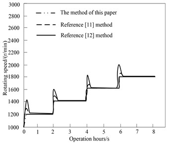
To verify the proposed method’s control performance on the BLDCM of electric vehicle, this method and the methods in Reference [11] and Reference [12] are compared. The initial speed of BLDCM of electric vehicle is set as 1200 r/min and increased by 200 r/min every 2 s. Set the period of the sinusoidal curve of the position as 1.6 s, the amplitude as 10°, and the simulation time as 5S. The response results of the three methods are shown in Fig. 6.
Experimental results in Fig. 6 show that the three methods can achieve the speed regulation of BLDCM of electric vehicle, and the performance of BLDCM of electric vehicle controlled by the method in Reference [11] is smaller than that in Reference [12]. But the best effect is the control performance of the proposed method. This method has the strengths including small error and fast response, and it also has no overshoot. Under the condition of sudden load, the speed drop of this method is smaller and has stronger ability to suppress disturbance. In the process of load operation, the proposed method can quickly adjust the speed to the given speed after receiving the signal of speed increase, and the speed fluctuation is small. The control effect of the method in Reference [12] is poor, the steady-state error is large, and the speed decreases significantly under load operation, with large deviation and severe fluctuation. Therefore, the ability of the proposed method to control BLDCM of electric vehicle is obviously better than that of the other two methods. It is verified that this method has good dynamic and static performance.
Fig. 6Response results of different methods to control BLDC motor
The application performance of BLDCM of electric vehicle controlled by the proposed method and other motors in electric vehicle is counted. The statistical results are presented in Table 1.
Table 1Performance comparison of electric vehicle drive motors
Parameter name | The method of this paper | Induction motor | Permanent magnet synchronous motor |
Size | Small | High | Middle |
Quality | Light | Middle | Middle |
Power density | High | Middle | Middle |
Peak efficiency | 0.98 | 0.95 | 0.95 |
Load efficiency | 0.98 | 0.93 | 0.92 |
Cost | Medium | High | High |
Through the comparison of Table 1, in general, the BLDCM controlled by the proposed method as the driving motor meets the requirements of electric vehicles. Compared with induction motor, the BLDCM controlled by this method has higher efficiency, smaller quality and size, and the control is relatively simple; Compared with permanent magnet synchronous motor (PMSM), the BLDCM controlled by this method has higher torque and energy density, and the control is relatively simple, which can reduce the cost; Compared with switched reluctance motor, the BLDCM controlled by this method has higher efficiency, less noise and vibration. The overall performance of BLDCM is good, and the cost of permanent magnet materials will decrease with the progress of technology, which has a broad prospect. Through the above comparative analysis, the BLDCM controlled by the proposed method is highly applicable as the driving motor of electric vehicle.
4. Discussion
The discrete SMC of BLDCM of electric vehicle is realized by PSO algorithm. According to experimental results, the proposed method has high control performance. Due to motor current commutation and its own design characteristics, BLDCM of electric vehicle generally has the problem of torque ripple, which restricts its application to a certain extent. There are three main factors affecting the torque ripple of BLDCM of electric vehicle:
(1) Influence of current commutation.
When the BLDCM operates, the power switches are turned on and off in order. Because of the existence of internal resistance and inductance of each winding, the instantaneous change of current is affected, and torque pulsation occurs when the current in the AW is reversed. The torque ripple generated by this commutation is the largest one of the torque ripple generated by the motor.
(2) Electromagnetic influence.
If the BLDCM works in the ideal state, the current waveform should be square and the back EMF waveform should be trapezoidal. However, in fact, due to the mechanical manufacturing level and material properties, the back EMF waveform may not be standard, and the crest width may not be 120° electrical angle; When the accuracy of the control system is not high, the electromotive force waveform and current cannot be synchronized, and the current waveform is distorted. This torque ripple is called electromagnetic torque ripple.
(3) Alveolar effect.
There are stator teeth in BLDCM, which leads to the change of inner pole reluctance in magnetic state and produces cogging torque. Especially when the BLDCM runs at low speed, the cogging torque is particularly prominent, which produces vibration and noise, which affects the performance and control accuracy of the motor. Such torque ripple is also known as reluctance torque ripple. At present, different solutions are adopted for different reasons caused by torque ripple of BLDCM.
The torque ripple generated by the characteristics of the motor can be reduced by improving the motor design and manufacturing technology; The torque ripple generated by current commutation can be improved by adding advanced control methods to the motor control. In this study, PSO algorithm is adopted to achieve the discrete SMC of BLDCM of electric vehicle to improve the control performance of BLDCM of electric vehicle and make the application of BLDCM in electric vehicle more widely.
5. Conclusions
In this paper, a discrete SMC on the basis of PSO algorithm is constructed for BLDCM of electric vehicle. Using PSO algorithm to get the optimal parameters of discrete SMC can effectively weaken the chattering of discrete SMC. Using PSO algorithm can effectively improve the control performance of discrete SMC for BLDCM of electric vehicle. According to experimental simulation results, the control method can track various signals better, and has the strengths including fast response speed, high control accuracy and strong anti-interference ability. Through the discrete SMC of BLDCM of electric vehicle, and comparing the position control error and control voltage of BLDCM of electric vehicle, it is verified that the discrete SMC optimized by PSO can effectively weaken the flat top and chattering phenomenon of BLDCM of electric vehicle. This method has small amount of calculation and obvious effect, and is easy to control the BLDCM of electric vehicle.
References
-
N. Saed and M. Mirsalim, “Enhanced sensor‐less speed control approach based on mechanical offset for dual‐stator brushless DC motor drives,” IET Electric Power Applications, Vol. 14, No. 5, pp. 885–892, May 2020, https://doi.org/10.1049/iet-epa.2019.0625
-
Y. Cao, T. Shi, Y. Yan, X. Li, and C. Xia, “Braking torque control strategy for brushless dc motor with a noninductive hybrid energy storage topology,” IEEE Transactions on Power Electronics, Vol. 35, No. 8, pp. 8417–8428, Aug. 2020, https://doi.org/10.1109/tpel.2020.2964434
-
Y. Zhang, H.C. Wang, H.F. Wei, Y.J. Li, K.L. Li, and W.T. Liu, “New fault‐tolerant control method for Hall signals in brushless DC motor driver of E‐bicycle,” Electronics Letters, Vol. 56, No. 6, pp. 284–286, Mar. 2020, https://doi.org/10.1049/el.2019.3143
-
Y. Zhu, H. Wu, and C. Zhen, “Regenerative braking control under sliding braking condition of electric vehicles with switched reluctance motor drive system,” Energy, Vol. 230, No. 7, p. 120901, Sep. 2021, https://doi.org/10.1016/j.energy.2021.120901
-
C. Napole, M. Derbeli, and O. Barambones, “A global integral terminal sliding mode control based on a novel reaching law for a proton exchange membrane fuel cell system,” Applied Energy, Vol. 301, No. 5, p. 117473, Nov. 2021, https://doi.org/10.1016/j.apenergy.2021.117473
-
J. H. Huang, J. H. Yang, H. F. Chen, and H. R. Cai, “Decoupling sliding mode chaos control with pso of permanent magnet linear synchronous motor,” Computer Simulation, Vol. 38, No. 11, pp. 215–220, 2021, https://doi.org/10.3969/j.issn.1006-9348.2021.11.044
-
Z. Jia, Q. Zhang, and D. Wang, “A sensorless control algorithm for the circular winding brushless dc motor based on phase voltages and dc current detection,” IEEE Transactions on Industrial Electronics, Vol. 68, No. 10, pp. 9174–9184, Oct. 2021, https://doi.org/10.1109/tie.2020.3018057
-
L. Cao, K. T. Chau, C. H. T. Lee, and H. Wang, “A double-rotor flux-switching permanent-magnet motor for electric vehicles with magnetic differential,” IEEE Transactions on Industrial Electronics, Vol. 68, No. 2, pp. 1004–1015, Feb. 2021, https://doi.org/10.1109/tie.2020.2969101
-
A. Credo, G. Fabri, M. Villani, and M. Popescu, “Adopting the topology optimization in the design of high-speed synchronous reluctance motors for electric vehicles,” IEEE Transactions on Industry Applications, Vol. 56, No. 5, pp. 5429–5438, Sep. 2020, https://doi.org/10.1109/tia.2020.3007366
-
G. Curiel-Olivares, J. Linares-Flores, J. F. Guerrero-Castellanos, and A. Hernández-Méndez, “Self-balancing based on active disturbance rejection controller for the two-in-wheeled electric vehicle, experimental results,” Mechatronics, Vol. 76, No. 1, p. 102552, Jun. 2021, https://doi.org/10.1016/j.mechatronics.2021.102552
-
M. Ebadpour, N. Amiri, and J. Jatskevich, “Fast fault-tolerant control for improved dynamic performance of hall-sensor-controlled brushless dc motor drives,” IEEE Transactions on Power Electronics, Vol. 36, No. 12, pp. 14051–14061, Dec. 2021, https://doi.org/10.1109/tpel.2021.3084921
-
B. Zheng, Y. Cao, X. Li, and T. Shi, “An improved dc-link series IGBT chopping strategy for brushless dc motor drive with small dc-link capacitance,” IEEE Transactions on Energy Conversion, Vol. 36, No. 1, pp. 242–252, Mar. 2021, https://doi.org/10.1109/tec.2020.3008902
-
S. Ding, M. Cheng, J. Hang, and L. Sun, “Segment design of the complementary magnetic-geared dual-rotor motor for hybrid electric vehicles,” Electrical Engineering, Vol. 102, No. 4, pp. 2109–2122, Dec. 2020, https://doi.org/10.1007/s00202-020-01013-7
-
B. Dianati, S. Kahourzade, and A. Mahmoudi, “Optimization of axial-flux induction motors for the application of electric vehicles considering driving cycles,” IEEE Transactions on Energy Conversion, Vol. 35, No. 3, pp. 1522–1533, Sep. 2020, https://doi.org/10.1109/tec.2020.2976625
-
X. Zhou et al., “A high-efficiency high-power-density on-board low-voltage DC-DC converter for electric vehicles application,” IEEE Transactions on Power Electronics, Vol. 36, No. 11, pp. 12781–12794, Nov. 2021, https://doi.org/10.1109/tpel.2021.3076773
-
M. Rubagotti, G. P. Incremona, D. M. Raimondo, and A. Ferrara, “Constrained nonlinear discrete-time sliding mode control based on a receding horizon approach,” IEEE Transactions on Automatic Control, Vol. 66, No. 8, pp. 3802–3809, Aug. 2021, https://doi.org/10.1109/tac.2020.3024349
-
Y. Zhu and L. Ma, “Composite chattering-free discrete-time sliding mode controller design for active front steering system of electric vehicles,” Nonlinear Dynamics, Vol. 105, No. 1, pp. 301–313, Jul. 2021, https://doi.org/10.1007/s11071-021-06465-5
-
R. Yang, W. X. Zheng, and Y. Yu, “Event-triggered sliding mode control of discrete-time two-dimensional systems in ROESSER model,” Automatica, Vol. 114, No. 5, p. 108813, Apr. 2020, https://doi.org/10.1016/j.automatica.2020.108813
-
F. Setoudeh and A. Khaki Sedigh, “Minimum variance control of chaos in a hyperchaotic memristor based oscillator using online particle swarm optimization,” Physica Scripta, Vol. 96, No. 3, p. 035221, Mar. 2021, https://doi.org/10.1088/1402-4896/abdaef
-
S. M. Abedi Pahnehkolaei, A. Alfi, and J. A. T. Machado, “Convergence boundaries of complex-order particle swarm optimization algorithm with weak stagnation: Dynamical analysis,” Nonlinear Dynamics, Vol. 106, No. 1, pp. 725–743, Sep. 2021, https://doi.org/10.1007/s11071-021-06862-w
Cited by
About this article

The authors have not disclosed any funding.
The datasets generated during and/or analyzed during the current study are available from the corresponding author on reasonable request.
The authors declare that they have no conflict of interest.
