Abstract
This paper is considered with a non-linear suspension design for half vehicle model by using particle swarm optimization technique. To analyze the ride comfort, a five-degree of freedom system is built, and it is integrated with the Particle Swarm Optimization (PSO) for optimizing the vehicle vibrations. A multi-objective function is proposed as the sum of the minimum seat and vehicle body acceleration, the minimum suspension deflection and the constraints and the design variables of the optimization problem are selected as the spring and damping coefficients of the front and rear suspension and the non-linear spring and the linear damping coefficients of the seat. The simulations are carried out and the results are compared with the non-optimized values. It is demonstrated that the vehicle vibration is decreased significantly with the help of the optimum values of the suspension parameters.
1. Introduction
The vehicle vibration is one of the most important issues for the vehicle design process and many researches has been performed on this important topic in order to obtain high ride comfort. The vibration is mainly caused by road profile it should be compensated by using a well-designed suspension system. The suspension systems are generally divided into three main categories: Passive suspension, semi-active suspension and active suspension system [1-3]. Among them, the most common one is the passive suspension system because of its simplicity, efficiency and low cost [4]. In this type of suspension system, the spring and damper have the predefined characteristic, while in the semi-active and active suspension system, the reaction forces are controlled. On the other hand, by adding a non-linear spring into passive suspension, one can provide a more proper vibration response for different road profiles.
The vehicle vibration is analyzed by using three main mathematical models: Quarter vehicle model (QVM) [5, 6], half vehicle model (HVM) [7] and full vehicle model (FVM) [8]. The simplest of these is the QVM. This model supposes that the vehicle moves only in the vertical direction while HVM has four degrees of freedom (DOF) and it is used to determine the characteristic of the pitch motion as well. If the roll behavior of the vehicle needs to be analyzed, the most complex model, FVM, should be used, which has seven DOF. Furthermore, the seat and human model can be added to these models as well [9].
The optimization of vehicle vibration is very important to achieve better ride comfort and many tools are available for solving such complex engineering problems. The optimization problem can be solved by using a deterministic or a stochastic method that solves the objective function with systematical random inputs. One of the most common stochastic optimization methods is the Particle Swarm Optimization (PSO) technique and it has been applied for many different engineering problems as well as vehicle vibration.
In this paper, a half vehicle model is considered with non-linear seat suspension and five equations of motion are derived and then they are integrated with Particle Swarm Optimization (PSO) algorithm. The design variables of the optimization problem are the spring and damping coefficients of the front and rear suspension, and the non-linear spring and the linear damping coefficients of the seat. The objective function of the optimization problem is defined as the sum of the minimum seat and vehicle body acceleration and the minimum suspension deflection. The simulations are performed, and the results are compared with the non-optimized simulations. It has been found that much lower vibration amplitudes can be achieved by using optimum suspension parameters.
2. Mathematical model of 5 DOF vehicle
In this chapter, the mathematical model of the vehicle is derived to characterize the vehicle vibration with non-linear seat suspension. As shown in Fig. 1, the half vehicle model with non-linear seat spring system has five DOF: The vertical motion of the front () and rear wheel (), the vertical () and pitch motion of the vehicle body () and the vertical motion of the seat ().
Fig. 1A schematic diagram of a half vehicle model
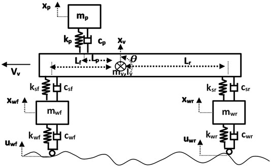
In the mathematical model, the seat spring force is considered as a cubic non-linear term:
where the and are the spring coefficients of the seat suspension. Considering Newton-Euler approach, the equation of motions of HVM are derived as below:
where the , and denote the mass of front wheel, rear wheel and vehicle body while , and , are the stiffness and damper coefficients of the front and rear wheels respectively. The parameters , and , represent the stiffness and damper coefficients of the front and rear suspension system, which are the design variables. Also, the and indicate the pith angle and the mass moment of the inertia of the vehicle body while , and are the distance from the rear suspension, front suspension and passenger axes to the center of gravity respectively. The subscript and denote the front and rear wheel.
The input road profile is represented with and it can be defined as a sinus function and it is given in Fig. 2 by using following equations:
where and represent the angular frequency and the vehicle velocity which are equal to and . The amplitude of the road profile is 0.05 m, and the period of it 11.1 m.
Table 1Half vehicle parameters with the range of design variables
Parameter | Value/range | Parameter | Value/range |
[kg] | 60 | [Ns/m] | 10 |
[kg] | 50 | [Ns/m] | 10 |
[kg] | 700 | [Ns/m] | 100-1500 |
[kg] | 95 | [Ns/m] | 100-1500 |
[kN/m] | 190 | [Ns/m] | 100-1500 |
[kN/m] | 190 | [kgm2] | 1400 |
[kN/m] | 15-55 | [m] | 1.2 |
[kN/m] | 15-55 | [m] | 1.7 |
[kN/m] | 25-105 | [m] | 0.4 |
[kN/m] | 2500-10500 | [m/s] | 22.2 |
3. PSO optimization algorithms and its procedures
Particle Swarm Optimization (PSO) method is proposed by [10] firstly, which is a stochastic population-based optimization algorithm. The PSO algorithm is inspired by the group behavior of birds or fishes and it has a huge usage in the engineering applications [11]. A random group of particles is used to search the extreme point of the objective function and they follow the nearest ones in order to the find the best value of the target by means of the reproduced velocities until the finalize criteria is satisfied. About the PSO pseudo-codes more details are given as follows:
Step-1. Set parameters of PSO and generate the position of particles randomly according to the constrains and give the initial velocities to zero.
Step-2. Calculate the objective function and find the particle best position and global best of swarm.
Step-3. Update each particle position and velocity with the help of the equations (a) and (b). Restrict the velocity and position of particle in determined ranges to avoid exceeding the limits:
where 1, 2,…, , and is the swarm size, 1, 2,…, , and is the variable size, 1, 2,…, , the maximum number of iterations 50 is, is the particle velocity, is the position of the particle, and are the best position of particles and global best of swarm, and the coefficients 0.9 and 0.4. and are random numbers between (0, 1) while the coefficient of cognitive and social acceleration factors are 1.3 and 2.8 respectively.
Step-4. Update the particle best position and global best of swarm by evaluating the fitness of each particle.
Step-5. Finalize the iterations if the requested conditions are achieved. If is it not satisfied, return the step 3.
In order to achieve better ride comfort of the vehicle, there are three main characteristic requirements from the system: Low amplitude of the seat acceleration to improve the ride comfort and low tire deflection for better road-holding ability and low suspension working space. Thus, the objective function is determined as the sum of the maximum acceleration of the seat and the sum of the squares of the constraints. There are three constrain functions regarding the real working conditions of the vehicle suspension system. These are the maximum acceleration of the seat and the vehicle body. Therefore, the objective function () of the optimization problem and the three constrains (, and ) are given as below:
According to the penalty function approach, the square of the constrains are added to the objective function. Design parameters of the optimization problem are selected as follow and the upper and lower limits of them are presented in Table 1:
Since the minimum amplitude of vehicle vibration is requested for better ride comfort, the cost function given in Eq. (12) is minimized by using the PSO algorithm. This minimization is carried out by solving the five equations of motions given Eqs. (2-6) using fourth order Runge-Kutta methods. The input of the differential equations is the road excitations given in Eqs. (7, 8). The values of the parameters of the simulations are given in Table 1.
4. Optimization results
The optimization results of the design variables obtained from the simulations are given in Table 2. Furthermore, the performances of the PSO are compared with un-optimized simulations as illustrated in the Fig. 2. The un-optimized simulation is performed with the following initial values of the suspension: 35 kN/m, 750 Ns/m, 55 kN/m, 5500 kN/m.
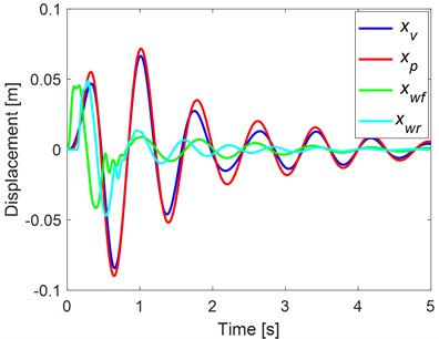
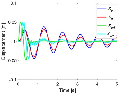
It is possible to see from the figure that the maximum amplitude of the seat and vehicle body acceleration are decreased significantly by using the optimization algorithm. The maximum seat acceleration of un-optimized simulation is 6.3965, while the maximum of optimized seat acceleration is equal to 3.1751. Thus, the maximum amplitude of the seat acceleration was reduced by about 50 percent. Similarly, the vehicle body acceleration is decreased by about 73 %. In Fig. 3, the displacements of the suspension system are illustrated to visualize the optimization effect. The results show that the optimum parameters can provide small amplitudes of displacements for the seat and the vehicle body. The constrains are also in the requested range, which are equal to –0.9729 m/s2, –0.0083 m and –0.0076 m.
Table 2The optimum design variables
Design variables | Optimization results |
[Nm] | 15000 |
[Nm] | 15000 |
[Nm] | 105000 |
[Nm] | 2500000 |
[Ns/m] | 1216.62 |
[Ns/m] | 99.99 |
[Ns/m] | 170.34 |
Fig. 2Optimized and un-optimized simulation results: a) seat and b) vehicle body accelerations
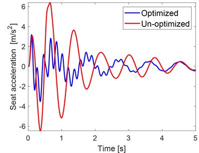
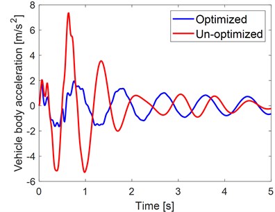
Fig. 3Simulation results: a) un-optimized and b) optimized displacements by using PSO algorithm
5. Conclusions
In this paper, five degrees of freedom of half vehicle with non-linear seat suspension model is handled to analyze and minimize the vehicle vibration for better ride comfort. A multi-objective function approach is used by using PSO algorithm. The design variables of the optimization problems are the stiffness and damping coefficients of the front and rear suspension, the non-linear and linear stiffness of the seat suspension and the damping coefficients of the seat. The fitness function is proposed as the sum of the minimum seat and vehicle body acceleration with constraints of optimization problems. The results of this paper show that the vibration amplitude can be decreased significantly thanks to the optimum design variables of the vehicle suspension by using PSO optimization technique. In future work, it is planning to validate these results by experiments and also to couple with different controller for the active suspension system.
References
-
Gillespie T. D. Fundamentals of Vehicle Dynamics. SAE International, Warrendale, 1996.
-
Jazar R. N. Vehicle Dynamics: Theory and Application. Springer International, New York, 2017.
-
Cao D., Song X., Ahmadian M. Editors’ perspectives: road vehicle suspension design, dynamics, and control. Vehicle System Dynamics, Vol. 49, Issues 1-2, 2011, p. 3-28.
-
Alkhatiba R., Nakhaie Jazarb G., Golnaraghi M. F. Optimal design of passive linear suspension using genetic algorithm. Journal of Sound and Vibration, Vol. 275, Issues 3-5, 2004, p. 665-691.
-
Kuznetsov A., Mammadov M., Sultan I., Hajilarov E. Optimization of a quarter-car suspension model coupled with the driver biomechanical effects. Journal of Sound and Vibration, Vol. 330, Issue 12, 2011, p. 2937-2946.
-
Gundogdu O. Optimal seat and suspension design for a quarter car with driver model using genetic algorithms, International Journal of Industrial Ergonomics, Vol. 37, Issue 4, 2007, p. 327-332.
-
Nariman Zadeh Salehpour N.-M., Jamali A., Haghgoo E. Pareto optimization of a five-degree of freedom vehicle vibration model using a multi-objective uniform-diversity genetic algorithm (MUGA). Engineering Applications of Artificial Intelligence, Vol. 23, Issue 4, 2010, p. 543-551.
-
Guclu R. Fuzzy logic control of seat vibrations of a nonlinear full vehicle model. Nonlinear Dynamics, Vol. 40, 2005, p. 21-34.
-
Ning D., Sun S., Li H., Du H., Li W. Active control of an innovative seat suspension system with acceleration measurement based friction estimation. Journal of Sound and Vibration, Vol. 384, Issue 11, 2016, p. 28-44.
-
Eberhart R. C., Kennedy J. A new optimizer using particle swarm theory. Proceedings of the 6th International Symposium on Micro Machine and Human Science, Nagoya, Japan, 1995.
-
Yildiz A. R. A novel particle swarm optimization approach for product design and manufacturing. The International Journal of Advanced Manufacturing Technology, Vol. 40, Issues 5-6, 2009, p. 617-628.
Cited by
About this article

