Abstract
For the lack of artificial experience in weighted matrix and in LQR optimal control algorithm of suspension, this paper proposed an optimal control strategy based on improved particle swarm optimization for semi-active suspension system. The paper mainly established a quarter vehicle semi-active suspension system model in MatLab, and wrote the S-function of the optimal controller. In addition, this article optimized weighted coefficient matrix of the state variable and the weighted coefficient matrix of the control variable in the linear quadratic regulator (LQR) [1] by utilizing the improved particle swarm optimization. The simulation results showed that the semi-active suspension system which based on the improved particle swarm optimization (IPSO) had better ride comfort and smoothness.
1. Introduction
As a connecting device between the vehicle’s body and wheel, the suspension can bear the weight of the body and isolate the impact and vibration of the vehicle body from the ground. The semi-active suspension system can adjust the suspension stiffness or damping coefficient according to the different driving conditions. It overcomes the technical defects of the passive suspension system and holds the advantage of low cost. In recent years, the semi-active suspension system has became a hot research topic in the suspension field [2]. In semi-active suspension system, the selection of control strategy is the key technology. LQR theory is a state space design method developed in modern control theory, which was the earliest and most proved theory. This theory got the optimal control law of state linear feedback, which is easy to form closed loop optimal control.
The state feedback controller that was designed by the LQR optimal controller required to get the minimum value of the linear quadratic target function , and the was determined only by the weighted matrix and , so it was particularly important to choose the and . In order to solve this problem, this paper proposed the optimal control strategy to IPSO. IPSO was a new type of optimization calculation technology which derived from the study of the predation behavior of flock birds. It belonged to the category of the stochastic global optimization technologies and had the characteristics of rapidity, effectiveness and robustness [3]. This paper was focused on two models, that was established the semi-active suspension system model and integral white noise road input model in MatLab, and applied the improved particle swarm optimization to optimize the weighting coefficient of the optimal controller.
2. The semi-active suspension model establishment
2.1. The filter white noise road input
Based on the known power spectral density of the road surface, the time-domain model of the road surface was established by the filter white noise [4] method, as follows:
where is the road displacement, is the lower cut-off frequency, is the road roughness coefficient, is the vehicle speed, is the filtered white noise.
2.2. The semi-active suspension model establishment
A reasonable assumption for the suspension system was made to establish the model of the quarter vehicle semi-active suspension system which had two degree of freedom, shown as in Fig. 1.
Fig. 1The model of the quarter vehicle semi-active suspension system
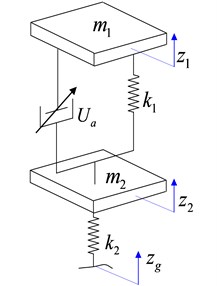
According to Newton second law, the motion differential equation of the semi-active suspension system which had two degree of freedom can be expressed as:
A dynamics model for two degree of freedom suspension system, the state variables of the system was , the input were the controller’s control force and the road disturbance , made .
The established state equation of the system was: :
3. The optimal controller establishment based on improved IPSO
3.1. The optimal controller establishment
The target of the optimal control of semi-active suspension was to make the vehicle getting higher ride comfort and smoothness. Therefore, the linear quadratic comprehensive performance index functional of semi-active suspension was defined as:
where is the weighting coefficient of body acceleration, is the weighting coefficient of suspension working space, and is the weighting coefficient of tires dynamic displacement, and the form of matrix was:
The and in the upper formula are refer to the weighted matrices of the state variables and the control variables respectively. The different values of and allowed the different weighting coefficients to be added to the different performance indexes in the function. After the calculation, the values of , , and were respectively as follows:
In the optimal controller of semi-active suspension, the state variable weighting coefficient matrix and the control variable weighted coefficient matrix are determined by the major experts who are known the prior knowledge. It was difficult to obtain the global optimal LQR controller. For semi-active suspension system of the vehicle, an important problem of the optimal control was determining the reasonable weighted coefficient value of the performance function. In order to control the weighted coefficient matrix better, this paper optimized the weighting coefficient , and of the optimal controller according to the particle swarm optimization, and then changed the state variable weighted coefficient matrix and the control variable weighted coefficient matrix, and obtained the different optimal control feedback gain matrix, and designed an optimal controller of semi-active suspension which could meet the requirements of riding comfort and smoothness [5].
3.2. The improved particle swarm optimization
In particle swarm optimization, each particle dynamically adjusted its speed and position according to its own flight experience and the group flight experience. Besides, each particle position represented the feasible solution of the optimization problem [6]. Given a D-dimensional searched space with particles, the iteration step was , the position and velocity of the th particle were (, , …, ) and (, , …, respectively. In each iteration, the particle dynamically adjusted its velocity vector to adjust its position according to the individual extreme (, , …, ) and the global extreme (,, …, ). The traditional particle swarm optimization algorithm was prone to premature convergence. In order to ensure the stability of the algorithm, this paper improved the particle swarm optimization, and introduced the contraction factor to ensure the convergence of the particle update [7]. Then the evolution equation of the velocity and position of the th particle was as follows:
In the formula, and are acceleration factors, and are the random number uniformly distributed between the sum of the [0 1], is the number of current iterations, is the contraction factor:
3.3. The optimal controller of the improved particle swarm optimization
The particle swarm optimization controller was proposed in this paper, the weighting coefficient was continuously improved according to the particle swarm optimization, so the feedback gain matrix was constantly updated. In order to call the optimal controller weighted matrix easily by the particle swarm program, the optimal controller was written in the MATLAB S-function. Part of the programs were follows as:
function [sys, x0, str, ts]n= mdl Initialize Sizes;
sizes = sim sizes;
sizes.Num Cont States = 0;
sizes.Num Disc States = 0;
sizes.Num Out puts = 1;
sizes.Num Inputs = 5;
sizes.Dir Feed through = 1;
sizes.Num Sample Times = 1;
[K, S, E] = lqr(A, B, Q, R, N);
sys = – K * u.
This paper selected fitness function as:
where , is the body acceleration in step and step ; , is the suspension working space in step and step ; , is the Tires Dynamic Displacement in step and step . The model parameters of vehicle semi-active suspension system were shown in Table 1.
Table 1The parameters of vehicle semi-active suspension system
The parameters | The numerical |
Sprung mass / kg | 690 |
Unsprung mass / kg | 40.5 |
Suspension stiffness (kN⋅m-1) | 19.2 |
Suspension damping coefficient / (kN/ms-1) | 1.5 |
Tire stiffness / (kN·m-1) | 170 |
The simulation semi-active suspension model was established that based on the optimal control strategy of improved particle swarm optimization was shown in Fig. 2.
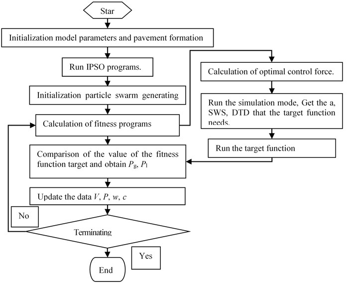
The program flowchart of the optimal controller based on IPSO is shown in Fig. 3.
The test vehicle passed the B level road surface with the uniform speed of 20 m/s, the lower cut-off frequency was 0.01 Hz, the white noise power was 20 dB, the solver was a fixed step ode4 solver [8], the simulation time was 10s. The optimal controller parameters were as follows: 2808, 614, 32, 1.0×105×[0.78, –0.20, 4.30, –5.6, 1.67]T.
Fig. 2The semi-active suspension model based on the optimal control strategy of improved particle swarm optimization
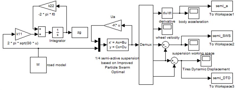
Fig. 3The program flowchart of the optimal controller based on IPSO
4. The simulation results
The time domain simulation results of vehicle body acceleration, suspension working space and tire dynamic displacement of semi-active suspension system were based on the improved particle swarm optimization were shown in Figs. 4-6.
Compared with the passive suspension, the semi-active suspension reduced the body acceleration, and then the suspension movement journey which was under the same tire dynamic displacement was well controlled in a certain range.
In order to further evaluate the optimal control effect of the improved particle swarm optimization, this paper analyzed the frequency response function of the body acceleration, the suspension working space and the tire dynamic displacement, as shown in Figs. 7-9.
Fig. 4The time domain curve of vehicle body acceleration
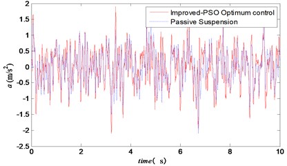
Fig. 5The time domain curve of suspension working space
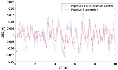
Fig. 6The time domain curve of tires dynamic displacement
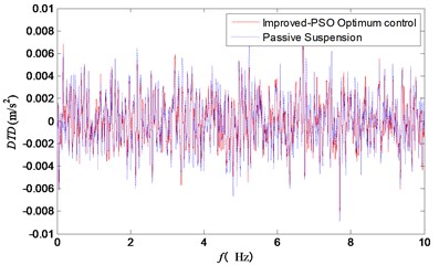
Fig. 7Frequency response curve of weighted body acceleration
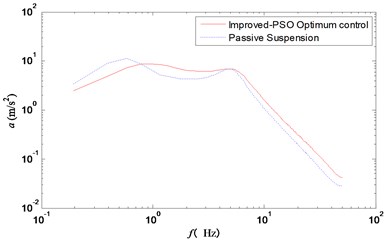
Fig. 8Frequency response curve of suspension working space
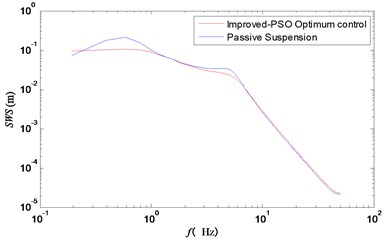
Fig. 9Frequency response curve of tires dynamic displacement
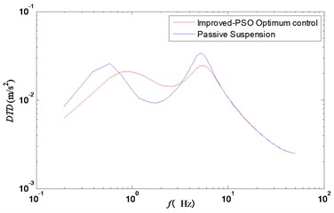
Fig. 6 showed the frequency domain curve of vehicle acceleration. Besides, the resonance frequency points of the wheel and the improved particle swarm optimization control could effectively reduce the vertical acceleration of the vehicle body. Figs. 7 and 8 showed clearly that the two peak values of suspension working space and tire dynamic displacement were significantly reduced under the improved particle swarm optimization control strategy.
References
-
Hubbard D. Survey of advanced suspension developments and related optical control applications. Automatic, Vol. 33, Issue 10, 1997, p. 1781-1817.
-
Wang Xiaopeng, Liu Jianjun, Wu Long A simulation research on seven-degree of freedom semi-active full vehicle suspension. Journal of Hunan University of Technology, Vol. 30, Issue 6, 2016, p. 12-17.
-
Chen Shuang, Zong Changfu Genetic particle swarm LQG control of vehicle active suspension. Automotive Engineering, Vol. 37, Issue 2, 2015, p. 189-193.
-
Yu Fan Vehicle Dynamics and Control. China Machine Press, Beijing, 2010.
-
Zhang Yufen, Long Jinlian, Li Jing, Lu Jiaxuan Research on LQG of active suspension based on immune particle swarm optimization. Computer Engineering and Applications, Vol. 54, Issue 6, 2018, p. 252-256.
-
Agrawal O. P., Shabana A. A. Application of deformable-body mean axis to flexible multibody system dynamics. Computer Methods in Applied Mechanics and Engineering, Vol. 56, 1986, p. 217-245.
-
Andries Engelbrecht P. Fundamentals of Computational Swarm Intelligence. John Wiley and Sons, 2011.
-
Song X., Ahmadian M. Characterization of semi-active control system dynamics with magneto-rheological suspensions. Journal of Vibration and Control, Vol. 16, 2010, p. 1439-1463.
About this article

Research was supported by Binzhou University Scientific research fund: PSO-fuzzy-PID Hybrid Control System Research, BZXYG1505, Binhou University Scientific research fund: Study on Torsional Vibration of Vehicle Transmission System, BZXYQNLG201206.
