Abstract
The lightweight development of electric vehicle motors is a prominent future trend, with the challenge of transmission vibration and noise acting as a key bottleneck that limits the enhancement of power and speed in electric vehicle drive systems. The noise generated by electric vehicle transmissions is primarily associated with the transmission system and gear structure. In line with this, the present study proposes an analysis of transmission error and response mechanisms through gear modifications. The research delves into the analysis of gear deformation and error generation characteristics. It further investigates methods for parametric equation modeling, tooth profile modification, deformation imprint analysis, and vibration response modeling to examine excitation response analysis and noise reduction techniques pertaining to transmission errors. The findings demonstrate that, under 40 % torque, the shaped gear exhibited a maximum reduction in transmission error of 34.2 %, resulting in an overall error improvement of over 5.7 %. Moreover, the maximum error difference after tooth profile and tooth direction shaping exceeded 2 %. The gear-shaping-based electric vehicle transmission showcased favorable economic and technical performance, while its excitation response mechanism provided valuable guidance for mass production. Overall, these results highlight the significance of analyzing transmission errors through gear modifications in achieving lightweight electric vehicle motors. By addressing transmission vibration and noise issues, this research contributes to overcoming limitations and promoting advancements in power and speed within electric vehicle drive systems.
1. Introduction
The increasing promotion of new energy development has created significant growth opportunities and potential for electric vehicles. The operational performance of electric vehicles is greatly influenced by their power train and control systems. Among these components, vehicle transmission plays a crucial role in meeting the driving requirements across various working conditions. Despite its relatively simple structure, it can achieve maximum speeds of up to 20,000 revolutions per minute [1]. Electric vehicle transmissions consist primarily of gears, drive shaft systems, bearings, and cases, among other components. However, differences in processing and manufacturing conditions, installation and commissioning methods, and load fluctuations inevitably lead to automotive error outcomes. Moreover, the meshing process of gears can generate noise, which in turn causes vibration in other parts, resulting in radiated noise [2, 3]. When an object vibrates, it emits sound waves that disturb the surrounding air. When these sound waves interfere with individuals, they are perceived as noise. The vibration and noise produced by the transmission system can significantly impact vehicle performance. Initially, the assessment of transmission noise sources relied heavily on vibration and noise tests conducted on transmission prototypes. Through repeated comparative experiments, the vibration conditions were adjusted until they met the noise criteria [4]. However, the emergence of noise simulation has expedited and improved transmission vibration detection, making it faster and more accurate. As a typical gear transmission system, vibration noise in electric vehicles is primarily attributed to the gear meshing process. This process is characterized by wheel deformation and manufacturing errors, which subsequently give rise to transmission errors [5]. Therefore, this research focuses on investigating the mechanisms behind transmission errors within the gear transmission system. By employing gear modifications and designing relevant parameter models, the aim is to reduce vibration errors and minimize the noise generated during operation.
2. Related works
Improving the torque vector control of an electric vehicle drive train is of great importance in terms of safety. Additionally, adjusting the reference understeer characteristics of the vehicle can effectively reduce energy consumption [6]. Scholar Kim S. proposed a gear control strategy for parallel hybrid electric vehicles based on speed and torque state feedback. They designed a multivariable control scheme incorporating H∞ loop formation. Experimental results demonstrate that this method improved the performance of observation controllers [7]. In another study, scholar Lin C. introduced a dual motor coaxial propulsion system suitable for all weather conditions. The results showed that the dual motor coaxial propulsion system offered superior gear calibration functionality and application effectiveness compared to a single-motor transmission [8]. Based on the flexible combination of power and torque at the electrical ports, scholar Zhu X. proposed a multi-port magnetic planetary gear permanent magnet motor. Experimental results validated the effectiveness of this method through prototype testing [9]. Scholars Holjevac N. employed computer-aided engineering to optimize vehicle energy consumption and performance. Simulation results indicated that the internal combustion engine significantly influenced vehicle energy consumption. Moreover, the careful selection of the number of electric motors and transmissions played a crucial role in enhancing vehicle performance [10]. Scholar Guercioni G. R. analyzed the transmission system of a series-parallel hybrid electric vehicle architecture and conducted stage analysis and equation design for its shift control strategy. The results indicated that the controller exhibited good application performance in nonlinear dynamic models [11]. Scholar Jiang S. conducted theoretical derivations and modal energy analysis on the multi-stage gear transmission system of permanent magnet synchronous motors, considering electromagnetic effects and torsional resonance characteristics. The results highlighted the potential risk of meshing stiffness resonance in synchronous motors during varying gear conditions [12]. Drawing from the relationship between harmonic torque and electric vehicle drive system performance, scholar Hu J proposed an electromechanical coupling dynamics model that considers inverter and transmission system characteristics. They applied a harmonic torque suppression strategy to the model. The results demonstrated that this strategy effectively reduced the dynamic load of the system, enhancing the stability and service life of motor operation [13].
Katz A. conducted an analysis of the relationship between the elastic deflection of the cutting tool and the gear tooth profile error. The results revealed a strong correlation between the simulated profile error and the lateral measurement profile of the gear. This highlighted the importance of enhancing the selection and development of electromechanical power train design parameters in improving the efficiency of electric vehicles [14]. Scholar Schweigert D analyzed the maximum speed and power of the electromechanical power system based on motor transmission characteristics. It was found that increasing the maximum speed of the motor had a significant impact on enhancing the power of the electromechanical power system [15]. In the field of hybrid vehicles, Tang X. proposed a novel approach that combines vision technology with deep reinforcement intelligent control algorithms. They applied visual ranging, control strategies, and energy strategies using deep Q-network learning. Experimental results demonstrated that this multi-objective control method ensured driving distance while simultaneously prioritizing fuel economy and driving safety [16]. Scholar Ritzmann J achieved the simplification of the whole vehicle model by considering torque distribution and gear selection in hybrid electric vehicles. This method outperformed dynamic programming in terms of performance advantages and required less time to implement the scheme [17]. To enhance the performance of electromechanical brake boosters, Wu J designed a nonlinear control method based on position tracking. The results indicated that the booster designed using this method exhibited excellent position tracking and response performance [18]. Li Y. proposed a two-layer scheduling model that considered demand responsiveness and uncertainty. Simulation results demonstrated that this method effectively balanced the problem between vehicle charging demand response and energy uncertainty [19]. Domingues-Olavarria G. developed a cost estimation framework for electric power systems. This framework enabled effective analysis and comparison of motor transmission ratio structure, power cost, and overload capacity [20].
From the above results, it can be seen that the construction of dynamic models and the introduction of computer-aided technology are common research ideas for the performance of electric vehicles. Previous studies have mostly focused on the torque and controller aspects of the transmission system, and have optimized the vehicle system model in many aspects. However, there is less focus on the influencing factors that cause gear changes in the transmission system, and the response mechanism for transmission error control is less involved. Therefore, research is conducted on the power analysis of gear transmission systems based on gear modification to better analyze their error control and vibration response and improve the performance of electric vehicles.
3. Gear transmission control analysis of electric vehicle transmission based on gear trimming
3.1. Transmission gearing mechanism under gear trimming
During practical operation, transmission systems can often experience vibration and noise-related challenges. These issues arise due to the intricate composition of internal components, leading to varying sources of noise. One major factor contributing to this is the dynamic meshing force excitation, which induces circular vibrations in the gears. Furthermore, vibrations occurring in the bearing bore, both radially and axially, transmit into the transmission shell's side wall. Consequently, the generated noise during this process propagates into the environment through the surrounding air medium. Figure 1 illustrates a schematic diagram showcasing the sources of noise excitation and the transmission path within the transmission gear system.
Fig. 1Schematic diagram of transmission vibration and noise generation mechanism and transmission path
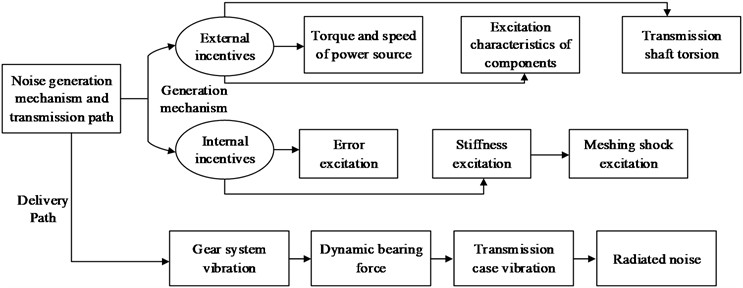
In the context of automobile gear trains, vibration noise primarily arises from transmission errors and excitation vibration noise caused by meshing-in and meshing-out shocks, time-varying stiffness, as well as mechanical vibration excitation and noise stemming from structural errors. Therefore, when designing transmissions for electric vehicles, it is crucial to not only focus on the performance of gear materials but also to consider their modification methods and parameters while controlling the error associated with their vibration and noise excitation sources. Transmission errors, being the intrinsic excitation affecting gear meshing systems, mainly result from manufacturing errors in gears and tooth profile deformations under load. Geometric dimensional errors that occur during the gear manufacturing process can change the contact points and increase vibration noise. However, non-variable errors can be optimized through the manufacturing process to reduce the impact of vibration noise. The mathematical formula for transmission error is shown in Eq. (1):
where, represents gear deformation, is tooth shape error under manufacturing error, is tooth pitch error under manufacturing error and is the trim curve [21]. The low-frequency noise of electric vehicle transmissions can have an impact on the noise, vibration, and acoustic roughness of the entire vehicle, and its wide speed range makes it easier for the transmission to overlap in operation. The internal excitation of the gear system in transmission has the most significant impact on its overall vibration noise. The extent of this excitation is influenced by various factors, such as machining and assembly errors, stiffness excitation resulting from changes in mesh stiffness, and abrupt shock excitation upon gear engagement and disengagement. Tooth pitch error and tooth shape error can have a significant impact on gear vibration noise, and both forms of error are shown in Fig. 2.
Fig. 2Tooth pitch error and tooth profile error
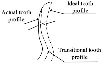
a) Tooth pitch error and tooth shape error
b) Mechanism of tooth shape error generation
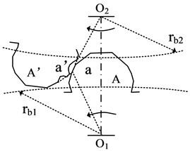
In order to achieve optimal meshing, the ideal tooth profile on the driving wheel should perfectly align with the actual tooth profile on the driven wheel. However, due to tooth shape errors, the contact point during the meshing process is shifted, denoted as point “a”, resulting in a change in gear ratio and subsequent dynamic excitation. Gear stiffness excitation refers to the phenomenon caused by the variation in mesh stiffness over time. To analyze the mechanisms behind this phenomenon, the study focuses on spur gears as an example. Fig. 3 illustrates the mechanism’s generation in detail.
Fig. 3Gear stiffness excitation mechanism and meshing stiffness curve
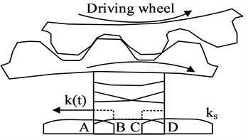
a) Gear stiffness excitation mechanism
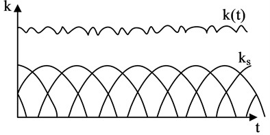
b) Meshing stiffness curve
When a single pair of teeth in gears mesh, they bear a relatively lower load, resulting in greater gear deformation. However, when two pairs of teeth are loaded, the gears experience less deformation and exhibit increased meshing stiffness. At the transition point between these two scenarios, a step phenomenon occurs. To mitigate load fluctuations, tooth profile modification is employed to reduce interference during meshing. The deformation of a single pair of teeth is primarily caused by the elastic deformation of the gear under load. According to the principle of deformation coordination, the meshing stiffness of a single pair of gears can be expressed using Eq. (2):
where, represents the mesh stiffness of the active wheel and is the mesh stiffness of the driven wheel. The study focuses on gears with varying tooth shapes, where the meshing process involves alternating between single and double teeth. The analysis is based on the involute tooth profile and utilizes a parametric equation model for representing the tooth profile. Mathematically, this can be expressed as Eq. (3), where the specific equation will depend on the particular gear shape being investigated:
where, is the radius of the pitch circle, is the angle of rotation, is the origin and is the point on the profile of the tangent wheel [7]. By fitting a multinomial function to the gear deformation curve, an approximate parabolic deformation curve of the gear teeth can be obtained under load. To study and design the deformation and stiffness curves of a single pair of teeth during the meshing process, their respective characteristics must be taken into account. This results in the derivation of Eq. (4), which provides the deformation and stiffness curves of a single pair of teeth during meshing:
where, is the minimum deformation, is the gear mesh stiffness and shows the end deformation amplification factor [22]. Based on the calculation results and the deformation coordination principle, the single and double tooth mesh stiffness curve can be determined in Eq. (5):
where, helical gears in the slicing method can be based on the contact line integral for stiffness and deformation calculations. Gears in the meshing process will be caused by the elastic deformation of the angle deviation is large. As the load increases, its elastic deformation will increase accordingly, while the manufacturing and installation and the system deformation of the error results will make the gear mesh surface, and the theoretical data there is a certain deviation. The study analyses the meshing errors in the time-varying state of the gear with the aid of simple harmonic functions, with base joint error and tooth shape error being the main influencing factors on gear vibration. The direction of the displacement excitation of the gear mesh on the meshing line can be expressed as Eq. (6):
where, is the gear error constant, is the magnitude of the error, is the time, is the meshing period and is the phase angle [23]. Also, the magnitude of the gear error can be expressed as Eq. (7):
where, indicates the base joint error and is the tooth profile error. The common ways of trimming are tooth profile trimming and tooth direction trimming, gear trimming is mainly to reduce the transmission error of gears in the meshing process. The deformation curve in the double tooth meshing zone will appear as a step, and the curve used in its exponential form when profile trimming is carried out in Eq. (8):
where, is the index of the trim curve, , is the maximum trim amount for the top and root of the tooth, and , , , are the starting points of trim for both wheels on the meshing line [24]. When the deformation of tooth meshing and the amount of trimming are minimal, resulting in low transmission error, the tooth width direction can be adjusted to accommodate manufacturing errors more effectively. The angle of gear bearing deformation in the direction of tooth width can be mathematically expressed as Eq. (9):
where, is the gear shaft support span, is the gear misalignment angle, is the gear helix angle tilt error, is the shaft parallelism error, and is the tooth width. Tooth directional reshaping mainly deals with the load distribution in the direction of tooth width to reduce the errors caused by machining and system deformation. The research design applies the axial slicing method for ellipse length and center position analysis to better accommodate the change in impression. The total load on the contact line can be expressed as Eq. (10):
where, is the maximum deflection of the normal load, , are the integral limits at the end of the contact line, is the stiffness effect function of the modification and is the engagement stiffness [25].
3.2. Vibration excitation response analysis of transmission errors
The reduction of transmission errors in automobiles is a dynamic problem that requires careful analysis. In electric vehicle transmissions, gears with large helix angles are often utilized to achieve smooth transmission and reduce system vibration noise. However, the complexity of gearing system components and the numerous vibration factors involved make analysis challenging. To simplify the problem, this study focuses on the dynamics of the system. Traditional gear vibration models involve many parameters, making it difficult to identify general design principles that can be easily applied. Additionally, these models often overlook the influence of other flexible components such as bearings. Furthermore, research on transmission systems has been relatively limited in terms of the selection of research objects. The electric vehicle transmission gear system serves to transmit drive energy through the gears. Accordingly, this study employs a gear pair meshing coupling model to analyze vibration, transforming it into a meshing line and establishing its coordinate system around this axis. The resulting transformed vibration model is depicted in Fig. 4.
Fig. 4Gear multi freedom vibration model
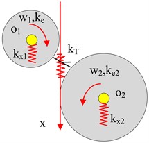
The transformed dynamical system of the gear consists of four degrees of freedom, representing the rotational motion of the main driven wheel, and four degrees of freedom, representing the translational motion along the meshing line. By applying Newton’s second law and disregarding the damping coefficient, the differential equation that governs gear vibration can be formulated, as shown in Eq. (11):
where, represents the mass matrix of the dynamic system, is the stiffness matrix, and , represent the displacement matrix, and the excitation force matrix. In the case of high-speed rotation, the vibration noise due to tooth shape error is the main aspect, while the gear deformation as a periodic function of the transmission error can be expressed as a function of the tooth frequency as the fundamental frequency. Therefore, assuming steady-state vibration under consideration of tooth shape error excitation only, the mathematical differential equation for vibration can be transformed into a two-mass vibration ordinary differential equation in Eq. (12):
where, is the mesh line displacement of the active wheel, are the mesh line displacements of the driven wheel, is the equivalent mesh line displacement of the input shaft, is the equivalent mesh line displacement of the output shaft, is the unit tooth width mass of the active wheel, is the unit tooth width mass of the driven wheel, is the equivalent elastic torsional stiffness of the drive shaft, is the excitation frequency, is the average mesh stiffness of the gear, is the periodic function, and is the transmission ratio. Different parameters in the gear system will make the errors show different forced vibrations. According to the amplitude-frequency characteristic curve of the gear rotation system, the transmission system can be transformed into a forced vibration model, the curve schematic is shown in Fig. 5.
Fig. 5Amplitude frequency characteristic curve of gear rotation system
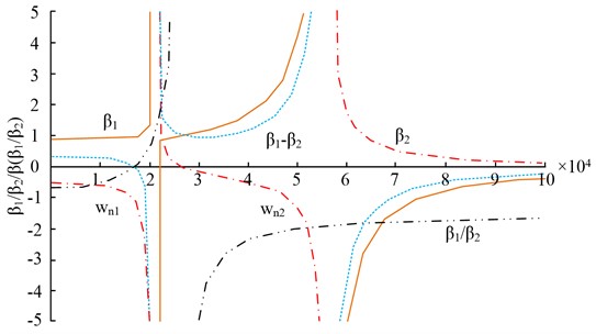
When the excitation frequency is zero, the forced motion of the two gears differs. However, as the excitation frequency increases, the gear motion becomes opposite to the excitation force, leading to a resonant phenomenon. The amplitude change of the gear train is influenced by the excitation frequency. To investigate this phenomenon, a dynamic model of the gear train and its internal dynamic excitation is constructed. The gear shaft system is parametrically modeled, considering factors such as the geometry of the shaft segments and their surface finish. Additionally, the gears are analyzed in terms of their drive train and the connection between the tooth shaft system. Fig. 6 illustrates the key elements involved in the technical construction of the dynamical model, including the gear train, internal dynamics excitation, gear shaft system, and differential analysis.
Fig. 6Technical route of transmission power simulation model
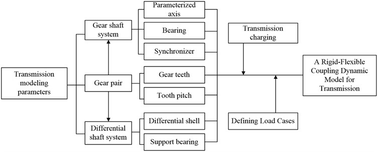
The transmission system is modeled by considering the gear train, gear subsystem, and differential shaft system. It is analyzed based on the charge and load conditions of the gearbox to construct its dynamics model. When studying transmission errors, the error signal in the time domain is represented by the rotational angle between the two gears. Eq. (13) provides a commonly used formula for calculating these errors:
where, , represent the rotational angular displacements of the master and driven wheels and , are the base circle radius of the master and driven wheels. To ensure accurate and consistent analysis of the error curve and sampling frequency of the gearing system, a meticulously designed test bench is implemented. This test bench comprises three main components: a precision mechanical system, a measurement and control system, and a software design. The measurement and control system, an integral part of the test bench, incorporates sensors and gratings. HBM flange torque transducers are utilized for both the drive and the loader, enabling precise measurement of torque. This system facilitates the collection of transmission error data, which is subsequently filtered and characterized to obtain relevant time domain characteristics. By employing this comprehensive test bench setup, the error curve and sampling frequency of the gearing system can be thoroughly analyzed with excellent repeatability and compatibility.
4. Application analysis of gear transmission error and response effect based on gear trimming
The gear transmission error situation reflected the quality of the gear mesh and the machining effect. An experimental design was carried out in a gear transmission error test rig. To avoid signal distortion caused by excessive data sampling frequency, the study conducted the transmission error test at low speed. The tooth ratio was set to 41:43, the gear speed ratio was set to 20 r/min, and the gear trim transmission error was analyzed at different torque levels. The results of this analysis are presented in Fig. 7.
Fig. 7Transmission error of gears before and after modification under torque conditions of 20, 40, 60, and 80 %
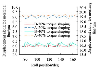
a) 20 % and 40 % torque
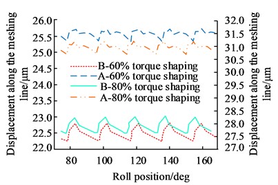
b) 80 % and 100 % torque
In Fig. 7, at 20 % and 40 % torque, the shaped gears show a slight increase in mesh displacement and a greater increase in the smoothness of the two operating curves, with a more significant reduction in the peak and trough values of transmission error for 20 % torque and a maximum reduction of 34.2 % for 40 % torque. The gears were shaped to show a change in transmission error of more than 30 %, which was a significant effect of gear shaping. The results of the error curve of the gears before and after the studied shaping method were then analyzed at 100 Nm, and the results are shown in Fig. 8.
In Fig. 8, before the gear was reshaped, the time domain curve of the period error was not smooth and there were abrupt changes. The time domain curve of the transmission error varied between the range of [–10, 10] and there were large magnitudes on the 1st, 3rd, and 4th order respectively, indicating that there were other disturbances in the gear in addition to the meshing excitation.
Fig. 8Time domain curve of periodic error, time domain curve of transmission error, and frequency domain curve of transmission error
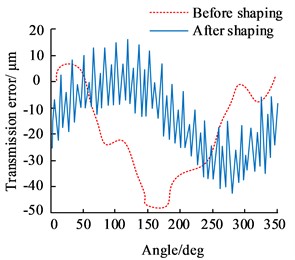
a) Periodic error time domain curve
b) Time domain curve of transmission error
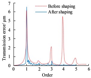
c) Frequency domain curve of transmission error
Fig. 9Transmission error before and after tooth profile and tooth alignment modification
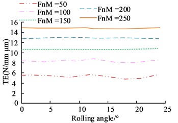
a) Before tooth profile modification
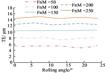
b) Before tooth alignment modification
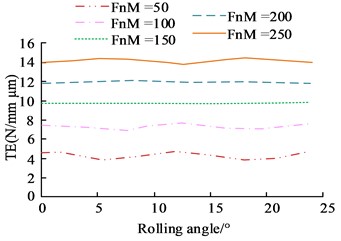
c) After tooth profile modification
d)After tooth alignment modification
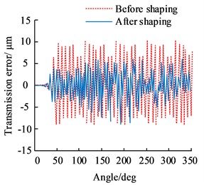
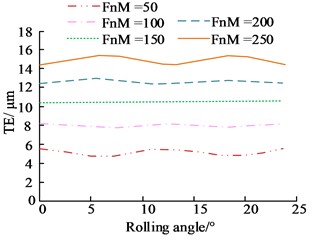
After gear modification, the periodic error curve of the gear exhibited a certain periodicity, and the fluctuation of its transmission error time-domain curve was improved to a certain extent, with a variation range of time domain curve [–7, 6]. The overall improvement in error shown before and after gear reshaping was over 5.7 %. The transmission errors before and after tooth profile and tooth orientation reshaping were analyzed at a consistent speed of 12,000 r/min for different operating conditions, the results of which are shown in Fig. 9.
In Fig. 9, the drive error was significantly reduced at 150 Nm and 200 Nm after profile reshaping, and the overall error curve exhibited significantly fewer fluctuating nodes and a smoother overall curve with a maximum error amplitude of 2.16 %. The tooth direction, after shaping, also showed a maximum difference of 2.34 % at 150 Nm. The results of the analysis of the peak transmission error situation under different methods of shaping are shown in Fig. 10.
Fig. 10Peak transmission error curve under different methods
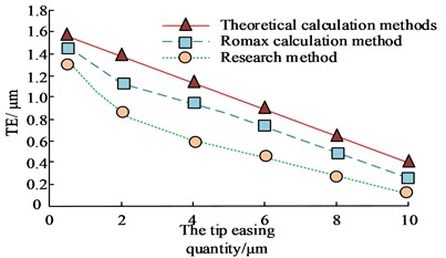
a) Tooth shape correction
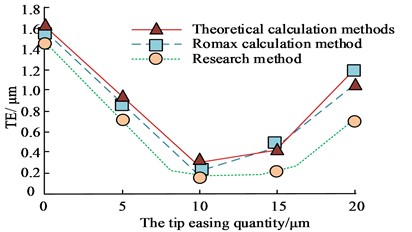
b) Tooth alignment correction
Fig. 11Vibration response of shell nodes before and after gear modification
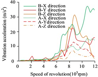
a) Node 1
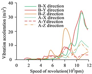
b) Node 2
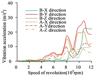
c) Node 3
The differences in the transmission error curves under different algorithms are shown in Fig. 10(a), where the peak transmission error curve after tooth profile trimming decreases significantly, with the peak error within 10 μm of the trimmed amount changing from 1.30 μm to 0.18 μm, the difference in magnitude of change (1.12 μm) being much smaller than the 1.18 μm and 1.14 μm of the theoretical method and the software Romax method. The reduction in the transmission error curve was also apparent after the profile had been reshaped, and although there was a certain rise in the peak value after the reshaping amount was greater than 10 μm, the value was still smaller than the other two methods. The nodes in the front, middle, and rear of the gear housing were selected for vibration response analysis and the results are shown in Fig. 11.
In Fig. 11, the vibration acceleration at different nodes of the housing was reduced to varying degrees after gear reshaping, with most of the speed range being around 50 % and 40 % in the and axes, and the reduction in the input axis being particularly pronounced at 7000 rpm. The transmission case naturally vibrated forcibly when external loads were present, and the vibration of the transmission was improved to a greater extent by reshaping the gears. The results of the analysis of the radiated noise at each measurement point of the transmission gear are shown in Fig. 12.
Fig. 12Radiated noise of transmission gears at various measurement points
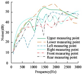
a) Before shaping
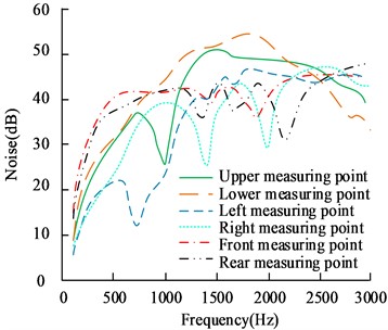
b) After shaping
In Fig. 12, the radiated noise at all six measurement points of the transmission changes to varying degrees before and after gear reshaping, with an average reduction of 8.25 dB at the six measurement points, with the most significant differences being at the right-hand and rear measurement points, with a maximum reduction of 12.11 dB and 10 dB.
5. Conclusions
The enhancement of optimal transmission design plays a crucial role in improving the driving performance of electric vehicles. This study focuses on analyzing the mechanism of error generation and response control through gear reshaping, as well as designing a performance check analysis system for transmission error control. The results revealed that the reshaped gear achieved a maximum reduction in transmission error of 34.2 % at a torque of 40 %. In terms of the time and frequency domain curves of gear transmission error, fluctuations occurred to some extent at 100 Nm. The time domain curves exhibited variations within the range of [–7, 6], with an overall improvement of more than 5.7 % in error. The maximum magnitude of error difference between profile and tooth orientation after trimming was found to be 2.16 % and 2.34 % respectively. Furthermore, the peak error in tooth orientation within a trim amount of 10 μm ranged from 1.30 μm to 0.18 μm using the trimming method proposed in this study. Importantly, the magnitude difference (1.12 μm) was significantly smaller compared to the theoretical method and the Romax software method, which reported magnitudes of 1.18 μm and 1.14 μm respectively. Regarding vibration response, the results demonstrated that gear reshaping led to a reduced vibration acceleration at the case nodes, especially notable in the and axes where reductions of approximately 50 % and 40 %, respectively, were observed across most speed zones. Remarkably, the input axis experienced a particularly pronounced reduction at 7000 rpm. Overall, these findings highlight that a transmission design reliant on gear trimming can effectively improve both driveline errors and vibration response noise in electric vehicles. However, future research should focus on further investigating the influence mechanism between the machining process and transmission error, warranting additional attention.
References
-
L. Jing, W. Tang, T. Wang, T. Ben, and R. Qu, “Performance analysis of magnetically geared permanent magnet brushless motor for hybrid electric vehicles,” IEEE Transactions on Transportation Electrification, Vol. 8, No. 2, pp. 2874–2883, Jun. 2022, https://doi.org/10.1109/tte.2022.3151681
-
X. Tang, J. Chen, H. Pu, T. Liu, and A. Khajepour, “Double deep reinforcement learning-based energy management for a parallel hybrid electric vehicle with engine start-stop strategy,” IEEE Transactions on Transportation Electrification, Vol. 8, No. 1, pp. 1376–1388, Mar. 2022, https://doi.org/10.1109/tte.2021.3101470
-
N. G. Lee et al., “A study on the improvement of transmission error and tooth load distribution using micro-geometry of compound planetary gear reducer for tractor final driving shaft,” Journal of Drive and Control, Vol. 17, No. 1, pp. 1–12, Mar. 2020, https://doi.org/10.7839/ksfc.2020.17.1.001
-
Z. He, Q. Shi, Y. Wei, J. Zheng, B. Gao, and L. He, “A torque demand model predictive control approach for driving energy optimization of battery electric vehicle,” IEEE Transactions on Vehicular Technology, Vol. 70, No. 4, pp. 3232–3242, Apr. 2021, https://doi.org/10.1109/tvt.2021.3066405
-
C. Panchal, S. Stegen, and J. Lu, “Review of static and dynamic wireless electric vehicle charging system,” Engineering Science and Technology, an International Journal, Vol. 21, No. 5, pp. 922–937, Oct. 2018, https://doi.org/10.1016/j.jestch.2018.06.015
-
G. de Filippis, B. Lenzo, A. Sorniotti, P. Gruber, and W. de Nijs, “Energy-efficient torque-vectoring control of electric vehicles with multiple drivetrains,” IEEE Transactions on Vehicular Technology, Vol. 67, No. 6, pp. 4702–4715, Jun. 2018, https://doi.org/10.1109/tvt.2018.2808186
-
S. Kim and S. B. Choi, “Cooperative control of drive motor and clutch for gear shift of hybrid electric vehicles with dual-clutch transmission,” IEEE/ASME Transactions on Mechatronics, Vol. 25, No. 3, pp. 1578–1588, Jun. 2020, https://doi.org/10.1109/tmech.2020.2980120
-
C. Lin, X. Yu, M. Zhao, J. Yi, and R. Zhang, “Collaborative control of novel uninterrupted propulsion system for all-climate electric vehicles,” Automotive Innovation, Vol. 5, No. 1, pp. 18–28, Feb. 2022, https://doi.org/10.1007/s42154-021-00170-0
-
X. Zhu, Z. Xiang, L. Quan, Y. Chen, and L. Mo, “Multimode optimization research on a multiport magnetic planetary gear permanent magnet machine for hybrid electric vehicles,” IEEE Transactions on Industrial Electronics, Vol. 65, No. 11, pp. 9035–9046, Nov. 2018, https://doi.org/10.1109/tie.2018.2813966
-
N. Holjevac, F. Cheli, and M. Gobbi, “A simulation-based concept design approach for combustion engine and battery electric vehicles,” Proceedings of the Institution of Mechanical Engineers, Part D: Journal of Automobile Engineering, Vol. 233, No. 7, pp. 1950–1967, 2019, https://doi.org/10.1177/0954407018777350.3
-
G. R. Guercioni and A. Vigliani, “Gearshift control strategies for hybrid electric vehicles: A comparison of powertrains equipped with automated manual transmissions and dual-clutch transmissions,” Proceedings of the Institution of Mechanical Engineers, Part D: Journal of Automobile Engineering, Vol. 233, No. 11, pp. 2761–2779, Sep. 2019, https://doi.org/10.1177/0954407018804120
-
S. Jiang, W. Li, Y. Wang, X. Yang, and S. Xu, “Study on electromechanical coupling torsional resonance characteristics of gear system driven by PMSM: a case on shearer semi-direct drive cutting transmission system,” Nonlinear Dynamics, Vol. 104, No. 2, pp. 1205–1225, Apr. 2021, https://doi.org/10.1007/s11071-021-06364-9
-
J. Hu, Y. Yang, M. Jia, Y. Guan, C. Fu, and S. Liao, “Research on harmonic torque reduction strategy for integrated electric drive system in pure electric vehicle,” Electronics, Vol. 9, No. 8, p. 1241, Aug. 2020, https://doi.org/10.3390/electronics9081241
-
A. Katz, K. Erkorkmaz, and F. Ismail, “Virtual model of gear shaping-part II: elastic deformations and virtual gear metrology,” Journal of Manufacturing Science and Engineering, Vol. 140, No. 7, p. 07100, Jul. 2018, https://doi.org/10.1115/1.4039651
-
D. Schweigert et al., “On the impact of maximum speed on the power density of electromechanical powertrains,” Vehicles, Vol. 2, No. 2, pp. 365–397, Jun. 2020, https://doi.org/10.3390/vehicles2020020
-
X. Tang, J. Chen, K. Yang, M. Toyoda, T. Liu, and X. Hu, “Visual detection and deep reinforcement learning-based car following and energy management for hybrid electric vehicles,” IEEE Transactions on Transportation Electrification, Vol. 8, No. 2, pp. 2501–2515, Jun. 2022, https://doi.org/10.1109/tte.2022.3141780
-
J. Ritzmann, G. Lins, and C. Onder, “Optimization method for the energy and emissions management of a hybrid electric vehicle with an exhaust aftertreatment system,” IFAC-PapersOnLine, Vol. 53, No. 2, pp. 13797–13804, 2020, https://doi.org/10.1016/j.ifacol.2020.12.888
-
J. Wu, H. Zhang, R. He, P. Chen, and H. Chen, “A mechatronic brake booster for electric vehicles: design, control, and experiment,” IEEE Transactions on Vehicular Technology, Vol. 69, No. 7, pp. 7040–7053, Jul. 2020, https://doi.org/10.1109/tvt.2020.2988275
-
Y. Li, M. Han, Z. Yang, and G. Li, “Coordinating flexible demand response and renewable uncertainties for scheduling of community integrated energy systems with an electric vehicle charging station: a bi-level approach,” IEEE Transactions on Sustainable Energy, Vol. 12, No. 4, pp. 2321–2331, Oct. 2021, https://doi.org/10.1109/tste.2021.3090463
-
G. Domingues-Olavarria, F. J. Marquez-Fernandez, P. Fyhr, A. Reinap, M. Andersson, and M. Alakula, “Optimization of electric powertrains based on scalable cost and performance models,” IEEE Transactions on Industry Applications, Vol. 55, No. 1, pp. 751–764, Jan. 2019, https://doi.org/10.1109/tia.2018.2864943
-
J. Wang, Y. Cai, L. Chen, D. Shi, R. Wang, and Z. Zhu, “Review on multi‐power sources dynamic coordinated control of hybrid electric vehicle during driving mode transition process,” International Journal of Energy Research, Vol. 44, No. 8, pp. 6128–6148, Jun. 2020, https://doi.org/10.1002/er.5264
-
H. Peng, D. Qin, J. Hu, and Z. Chen, “Analysis of the influence of power coupling type and transmission type of the powertrain on the performance of single-motor hybrid electric vehicles,” Proceedings of the Institution of Mechanical Engineers, Part D: Journal of Automobile Engineering, Vol. 236, No. 6, pp. 1285–1299, May 2022, https://doi.org/10.1177/09544070211033952
-
A. S. Maihulla, I. Yusuf, and S. I. Bala, “Reliability and performance analysis of a series-parallel system using Gumbel-Hougaard family copula,” Journal of Computational and Cognitive Engineering, Vol. 1, No. 2, pp. 74–82, 2021, https://doi.org/10.47852/bonviewjcce2022010101
-
Q. Sun, Y. H. Sun, and X. L. Ge, “Geometric modeling and manufacturing method for a few teeth involute gear with bilateral modification,” Solid State Phenomena, Vol. 287, pp. 40–46, Feb. 2019, https://doi.org/10.4028/www.scientific.net/ssp.287.40
-
A. Z. Hajjaj, K. Corrigan, M. Mohammadpour, and S. Theodossiades, “On the stability analysis of gear pairs with tooth profile modification,” Mechanism and Machine Theory, Vol. 174, p. 104888, Aug. 2022, https://doi.org/10.1016/j.mechmachtheory.2022.104888
About this article

The research is supported by: Huai’an Science and Technology Support Program (Industry) Project: Design and Analysis of Gear System of Pure Electric Vehicle Transmission (No. HAB202161).
The datasets generated during and/or analyzed during the current study are available from the corresponding author on reasonable request.
Linlin Zhao: conceptualization, methodology, writing-original draft preparation. Zhongwang Zhou: methodology, formal analysis, software. Tao Wu: writing-review and editing, formal analysis, validation.
The authors declare that they have no conflict of interest.
