Abstract
Vibration response of gears is an important indicator for gear mesh analysis as its value has been found to changing drastically with increase in number of cracks in gears. In the current study, the effect on vibration response for healthy gear and cracked gear has been investigated. High frequency amplitude modulated signal is taken as input and provides an output which is envelope of the original signal. ANSYS 20 software, MSC ADAMS along with MATLAB have been used to model the gears with multiple cracks induced. Structural analysis has been performed through Mechanical APDL. The vibration response values have been found to vary significantly with increase in number of cracks.
1. Introduction
Vibration response is an important parameter for dynamic analysis of mating gears. It is used in variety of fields to determine the displacement, velocity, and acceleration of any system. Steady operation is a need for the gear system. Vibration response of the gear system are found through mesh stiffness which continuously varies with time. Many scholars have contributed to the findings of healthy gear system. As soon as the cracks are inserted in the gears, its entire dynamics changes and leads to fluctuation in acceleration and velocity of gears.
Study of gear dynamics is not only essential to design reliable power transmission system with acceptable levels of gear vibration and noise but is also needed to study kinematical characteristics of mating gears with tooth profiles which are non-standard by applying the proposed mathematical model. Numerous mathematical models have been developed of gears for several purposes to find out the effect of crack on the mesh stiffness of gears and transmission error of gears. Methodology adopted for dynamic modelling of transmission is to find deflection of mating teeth with help of varying mesh stiffness to calculate meshing force. Many models assume both wheels can make a additional rotation with respect to constant motion due to base circle revolutions. By finding out meshing geometry [1-4], interference of tooth profiles can be determined.
Many researchers demonstrated effects of different crack lengths on their system vibration and calculated the residual signal using statistical indicators like RMS, Kurtosis and crest factor for the tooth crack detection. Demodulation techniques has been applied [8-10] from experimental setup to the raw vibration signal obtained and calculated the residual signal. For healthy gears, effect of single crack has been investigated by several researchers over the last two decades [12-16].
From the above discussion, it is evident that effects of different parameters and effect of single crack in gears have been the main focus of earlier researchers. Though the path of crack propagation was considered in some of these studies, the effect of multiple cracks on vibration response has not been studied in detail. Therefore, the effect of multiple cracks on vibration response of gears and change in values of parameters like acceleration and velocity has been investigated in the current study. Results obtained by the proposed mathematical model are in agreement with the experimental results available in the literature. The vibration response for increase in number of cracks have been computed and a comparison among all these values concludes the paper.
2. Theoretical background
Finite element model and lumped mass model are used for simulating gear systems with cracks. The lumped mass model is usually considered in case the shafts and the bearings supporting the gears are assumed to be rigid. For flexible shafts, finite element model is used. Different mathematical models have been developed for different purposes in the past decades. In the previous studies, main objective in the primary analysis of the gear system was to predict tooth dynamic loads for designing gears at high speeds. Different degree of freedom models like 4 DOF, 6 DOF, 8 DOF and 12 DOF models have been used for the lumped mass model systems.
The stress intensity factors are the major parameters to estimate the characteristics of crack. Weight function techniques which are analytical methods and several other numerical methods have been used by researchers to calculate tooth stress intensity factors.
Fig. 1A six DOF dynamic model
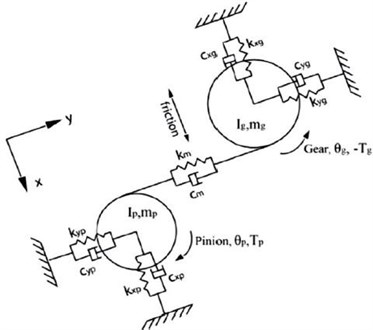
Following the work done by earlier researchers [1-12], six degree of freedom dynamic model has been developed. In the present study simulation was performed for both healthy and cracked cases and then gear mesh stiffness corresponding to crack sizes can be input into dynamic model. ODE45 function is used to build the model and solve the equations of motion. Experimental studies say that dynamic analysis should include time varying gear mesh stiffness and gear backlash. Dynamic models of gear pair transmission are classified in four categories as Linear Time Invariant model, Linear Time varying models which include time varying gear mesh stiffness, non-linear time invariant which include gear backlash and non-linear time varying models which include time varying gear mesh stiffness and gear backlash respectively. A complex model has been used following earlier researchers [15, 16] of finite elements that excludes many of the constructs that simplify them. At the shaft frequency, they discovered the system’s forced vibration response, excited by mass unbalances and performed gear errors using modal summation. But the high frequency, internal, static propagation, error excitation, which has the key function in producing noise, was not considered. In a recent paper by Gregory (1963) made a comprehensive study of linear mathematical models used in gear dynamics analysis is considered as the number of nonlinear contact forces in vertical direction at each contact point.
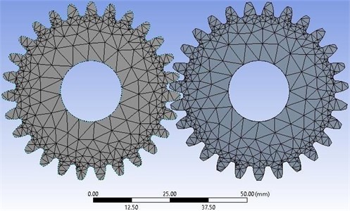
Using ANSYS software, the driving shaft and driven shaft are designed by the Beam188 element and the driving and driven gears are modeled by the Solid185 element. The nodes are coupled at holes of each gear and at the central axis, master node is coupled. Depending on the neutral file obtained from the ANSYS software, MSC ADAMS is used to develop the flexible model. The vibration signals of spur gears with multiple cracks are measured.
Table 1Parameters of gear model system used for analysis
Parameters | Value |
Contact type | Flex to flex |
Normal force | Impact |
Stiffness (N/mm) | 7.153×10⁵ |
Force exponent | 1.6 |
Damping (Ns/mm) | 51 |
Penetration depth (mm) | 0.1 |
Parameters | Value |
Rotating Speed (rev/min) | 1510 |
Time step | 2×10⁻⁵ |
Fig. 2Meshed spur gear with tetrahedron meshing
3. Results and discussion
Vibration response as discussed in the above section has been applied to a pair of spur gears. As stated in earlier section, vibration response has been calculated for a multiple cracked gear. The plots thus obtained are shown in Fig. 3-5. The signal processing procedure is applied to the defect induced gears in form of crack and vibration response. The other signals have also been processed following the same procedure. More distortions and fluctuations in amplitude is clearly observed in multiple cracked gears.
Fig. 3Wavelet transform for multiple cracks mesh stiffness with Level 5 decomposition
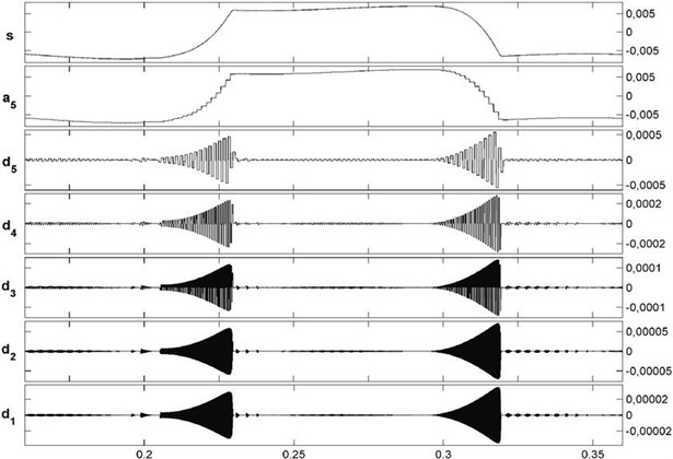
Fig. 4Vibration signal response of multiple cracked gears
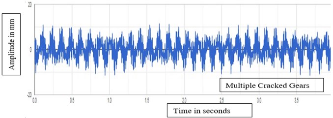
Fig. 5Vibration signal response of single cracked gears
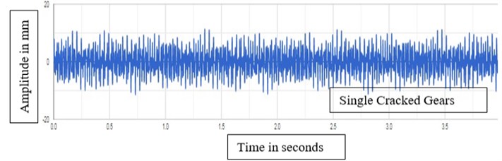
The plots reestablish the fact that the choice of decomposition has strong influence on modeling performance reflecting the importance of accurate wavelet-based data pre-processing practice. The best decomposition level selected from results is same for two decomposition types which means choice of suitable decomposition level is determined by time series analyzed but has no relation to decomposition type used. Level 5 decomposition gives better results for multiple cracks. Higher level of decomposition increases the accuracy of de-noising to a very high extent. More fluctuations in amplitude are clearly observed in multiple cracked gears as compared to single cracked gears as seen in Fig. 4 and Fig. 5.
4. Conclusions
In the present investigation, effect of multiple cracks on acceleration is found by wavelet transform Level 5 decomposition technique. The numerical results obtained from the study indicates that as the number of crack increases, fluctuations increase a lot in case of multiple cracked gears as compared to single cracked gears with more sidebands as seen clearly in Fig. 4 and Fig. 5. It is observed that the sideband amplitudes and its harmonic of cracked gears are much larger than that of healthy gears. Wavelet transform Level 5 decomposition clearly indicates huge fluctuations and distortions as compared to level 2 and level 1 decomposition as seen in Fig. 3 for multiple cracked gears. More level of decomposition clearly shows more de-noising in cracked gears.
References
-
J. Antoni and R. B. Randall, “Differential diagnosis of gear and bearing faults,” Journal of Vibration and Acoustics, Vol. 124, No. 2, pp. 165–171, Apr. 2002, https://doi.org/10.1115/1.1456906
-
Bajric R., Sprecic D., and Zuber N., “Review of vibration signal processing techniques towards gear pairs damage identification,” International Journal of Engineering and Technology IJET-IJENS, Vol. 11, No. 4, pp. 97–101, 2011.
-
C. G. Cooley, C. Liu, X. Dai, and R. G. Parker, “Gear tooth mesh stiffness: A comparison of calculation approaches,” Mechanism and Machine Theory, Vol. 105, pp. 540–553, Nov. 2016, https://doi.org/10.1016/j.mechmachtheory.2016.07.021
-
S. Wu, M. J. Zuo, and A. Parey, “Simulation of spur gear dynamics and estimation of fault growth,” Journal of Sound and Vibration, Vol. 317, No. 3-5, pp. 608–624, Nov. 2008, https://doi.org/10.1016/j.jsv.2008.03.038
-
Zhou Xiaojun, Zhou Xiaojun, Shao Yimin, Lei Yaguo, and Zuo Mingjian, “Time-varying meshing stiffness calculation and vibration analysis for a 16DOF dynamic model with linear crack growth in a pinion,” Journal of Vibration and Acoustics, Vol. 134, No. 1, pp. 1–11011, 2012.
-
Z. Chen and Y. Shao, “Dynamic simulation of spur gear with tooth root crack propagating along tooth width and crack depth,” Engineering Failure Analysis, Vol. 18, No. 8, pp. 2149–2164, Dec. 2011, https://doi.org/10.1016/j.engfailanal.2011.07.006
-
D. G. Lewicki and R. Ballarini, “Effect of rim thickness on gear crack propagation path,” Journal of Mechanical Design, Vol. 119, No. 1, pp. 88–95, Mar. 1997, https://doi.org/10.1115/1.2828793
-
O. D. Mohammed, M. Rantatalo, J.-O. Aidanpää, and U. Kumar, “Vibration signal analysis for gear fault diagnosis with various crack progression scenarios,” Mechanical Systems and Signal Processing, Vol. 41, No. 1-2, pp. 176–195, Dec. 2013, https://doi.org/10.1016/j.ymssp.2013.06.040
-
D. C. H. Yang and J. Y. Lin, “Hertzian damping, tooth friction and bending elasticity in gear impact dynamics,” Journal of Mechanisms, Transmissions, and Automation in Design, Vol. 109, No. 2, pp. 189–196, Jun. 1987, https://doi.org/10.1115/1.3267437
-
F. Chaari, W. Baccar, M. S. Abbes, and M. Haddar, “Effect of spalling or tooth breakage on gearmesh stiffness and dynamic response of a one-stage spur gear transmission,” European Journal of Mechanics – A/Solids, Vol. 27, No. 4, pp. 691–705, Jul. 2008, https://doi.org/10.1016/j.euromechsol.2007.11.005
-
F. Chaari, T. Fakhfakh, and M. Haddar, “Analytical modelling of spur gear tooth crack and influence on gearmesh stiffness,” European Journal of Mechanics – A/Solids, Vol. 28, No. 3, pp. 461–468, May 2009, https://doi.org/10.1016/j.euromechsol.2008.07.007
-
A. Parey and N. Tandon, “Spur gear dynamic models including defects: a review,” The Shock and Vibration Digest, Vol. 35, No. 6, pp. 465–478, Nov. 2003, https://doi.org/10.1177/05831024030356002
-
A. Parey, M. El Badaoui, F. Guillet, and N. Tandon, “Dynamic modelling of spur gear pair and application of empirical mode decomposition-based statistical analysis for early detection of localized tooth defect,” Journal of Sound and Vibration, Vol. 294, No. 3, pp. 547–561, Jun. 2006, https://doi.org/10.1016/j.jsv.2005.11.021
-
O. D. Mohammed, M. Rantatalo, and J.-O. Aidanpää, “Dynamic modelling of a one-stage spur gear system and vibration-based tooth crack detection analysis,” Mechanical Systems and Signal Processing, Vol. 54-55, pp. 293–305, Mar. 2015, https://doi.org/10.1016/j.ymssp.2014.09.001
-
Hui Ma, J. Zeng, Ranjiao Feng, X. Pang, Qi-Bin Wang, and B. Wen, “Review on dynamics of cracked gear systems,” Engineering Failure Analysis, Vol. 55, p. 224, 2015.
-
R. W. Cornell, “Compliance and stress sensitivity of spur gear teeth,” Journal of Mechanical Design, Vol. 103, No. 2, pp. 447–459, Apr. 1981, https://doi.org/10.1115/1.3254939
-
H. Endo, R. B. Randall, and C. Gosselin, “Differential diagnosis of spall vs. cracks in the gear tooth fillet region: Experimental validation,” Mechanical Systems and Signal Processing, Vol. 23, No. 3, pp. 636–651, Apr. 2009, https://doi.org/10.1016/j.ymssp.2008.08.015
About this article

