Abstract
This paper analyzes the compression process and the main factors affecting the compressibility of fluid in hydraulic shock absorbers during the impact process. Furthermore, the influences of the compressibility of fluid on characteristics of hydraulic shock absorbers are analyzed. In order to verify these analyses, modeling and simulation of a hydraulic shock absorber is carried out based on AMEsim.
Highlights
- The effective bulk modulus of fluid and the volume of the compression chamber can affect the compressibility of fluid when the hydraulic shock absorber consumes impact energy.
- Increasing the compressibility of fluid can reduce the maximum pressure and shorten the working stroke of the hydraulic shock absorber.
- Choosing hydraulic oil or other liquid with small bulk modulus as working medium.
- Containing an appropriate amount of air in the hydraulic oil.
- Increasing the volume of the compression chamber.
1. Introduction
Bulk modulus of pure hydraulic oil is about 1200-2100 MPa, which is a large numerical quantity. Therefore, in general hydraulic systems, the oil can be approximately considered as incompressible [1]. However, when cavitation occurs or the oil contains a certain amount of gas, the effective bulk modulus of mixed fluid will be reduced rapidly, Merritt discovered that the effective bulk modulus of oil MIL-H-5606 can be reduced down to 25 % of it’s pure state when contains 1 % gas [2]. Hydraulic shock absorbers are usually used to absorb transient impact energy, in which cases can usually cause huge transient flow rate and pressure change, these are the favorable conditions for cavitation and aeration and the compressibility of mixed fluid can be significantly enhanced [3-6]. The main purposes of this paper are to analyze the factors affecting the compressibility of fluid in hydraulic shock absorbers during the impact process and further to analyze the influences of the compressibility of fluid on characteristics of hydraulic shock absorbers.
2. Structure and working principle of hydraulic shock absorber
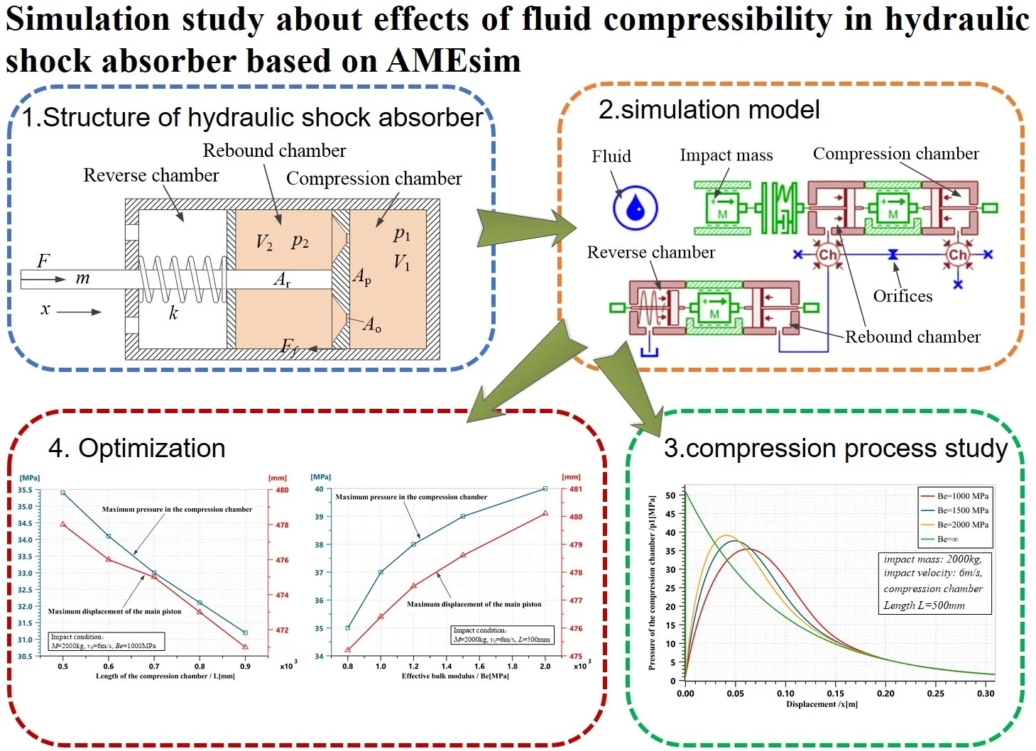
The structure of hydraulic shock absorber is shown in Fig. 1. The reverse chamber is integrated with the compression chamber and the rebound chamber in one cylinder. The compression chamber and the rebound chamber are oil chambers separated by the main piston, which is provided with a certain number of restrictors. In order to achieve more stable features and faster response, these restrictors on the main piston are designed as orifice plates instead of check valves and orifices. The reverse chamber is separated from the rebound chamber by a floating piston and with a return spring placed in to compensate for rod volume entering or exiting the rebound chamber.
At initial state, the fluid has an initial pressure and the main piston is pushed to the left side and the return spring is compressed at a certain length. When an impact force acting on the rod to drive the main piston moving toward right, the fluid pressure in compression chamber will increase and some fluid will flow into the rebound chamber through orifice plates with reduced pressure . Therefore, the pressure difference will generate a damping force on the main piston to resist the impact force and slow down the piston rod along with the external impact load.
Fig. 1The hydraulic shock absorber
3. Simulation analysis
3.1. Modeling and compression process study
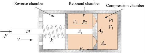
In order to verify the influences of fluid compressibility on the characteristics of hydraulic shock absorber, modeling of the hydraulic shock absorber shown in Fig. 1 has been implemented in AMESim simulation environment as shown in Fig. 2.
Fig. 2AMESim simulation model of the hydraulic shock absorber
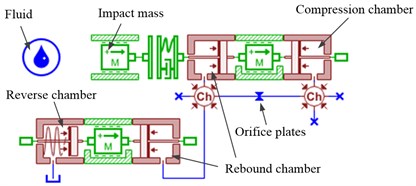
We run simulations under different parameters to study the compression process and how the factors affecting the compressibility of fluid in the hydraulic shock absorber. The results of the compression flow rate of fluid are shown in Fig. 3.
The compression flow rate curves shown in Fig. 3 demonstrate the compression process of fluid during the impact process. The positive value means compression while the negative value means expansion. All results show that the compression flow rate reaches to the maximum value at the first contact moment, that is because of the biggest velocity change of the main piston leads to the greatest pressure change gradient in the compression chamber [7]. Fig. 3(a) shows that the compression flow rate reduces more slowly and the maximum expansion flow rate is larger if the effective bulk modulus of fluid is smaller. Fig. 3(b) shows that the compression flow rate reduces more slowly and the maximum expansion flow rate is larger if the compression chamber length is shorter (that is, the volume of the compression chamber is smaller).
Fig. 3Simulation results of compression flow rate
a) Different effective bulk modulus
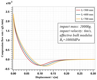
b) Different compression chamber length
3.2. Influences on characteristics
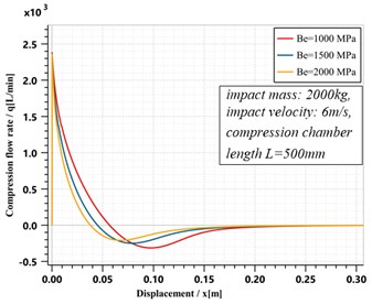
Different effective bulk modulus set are chosen to run some simulations to study these influences and the results are shown in Fig. 4.
Fig. 4Simulation results of characteristics of the hydraulic shock absorber
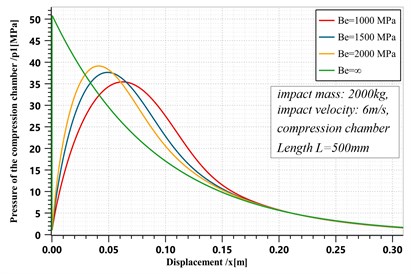
a) Pressure of the compression chamber
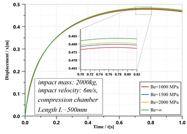
b) Piston displacement
Fig. 4(a) shows that if the fluid has smaller effective bulk modulus, which means the fluid is much easier to compress or expand, and the maximum pressure of the compression chamber of the hydraulic shock absorber is smaller. It can be concluded that when the fluid has a certain compressibility, the maximum pressure in the hydraulic shock absorber can be reduced, which is beneficial to the structural strength. Fig. 4(b) shows another feature of the hydraulic shock absorber. If the smaller effective bulk modulus of fluid is, the shorter working stroke required for the hydraulic shock absorber to consume the impact energy. The explanation for this phenomenon is that the compressible fluid can store some energy during the compression process and then to release this part of energy during the expansion process, which can make the compression chamber maintain a higher pressure within a longer displacement and improves work efficiency of the hydraulic shock absorber.
3.3. Optimization
According to the analysis in section 3.3, increasing the compressibility of the fluid can reduce the maximum pressure in the hydraulic shock absorber and shorten the working stroke. This can be achieved by reducing the effective bulk modulus of fluid or by increasing the volume of the compression chamber of the hydraulic shock absorber.
Fig. 5Optimization with Be
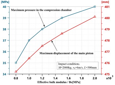
Fig. 6Optimization with L
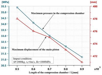
As shown in Fig. 5, when the effective bulk modulus of fluid reduces, the maximum pressure in the hydraulic shock absorber decreases and so as the working stroke. Alternative optimization approach is to increase the volume of the compression chamber in the hydraulic shock absorber. As shown in Fig. 6, when the length of the compression chamber increases, that is, the volume of the compression chamber increases, the maximum pressure in the hydraulic shock absorber decreases and so as the working stroke.
4. Conclusions
Based on simulation analysis, the effective bulk modulus of fluid and the volume of the compression chamber can affect the compressibility of fluid when the hydraulic shock absorber consumes impact energy. And these factors will ultimately affect the characteristics of the hydraulic shock absorber. Simulation results show that increasing the compressibility of fluid can reduce the maximum pressure and shorten the working stroke of the hydraulic shock absorber. This optimization can be achieved by choosing hydraulic oil or other liquid with small bulk modulus as working medium, or by containing an appropriate amount of air in the hydraulic oil, or by increasing the volume of the compression chamber.
References
-
Gu H. B., Ding Y. L. Effects of fluid compressibility on landing gear shimmy dampers. Journal of Nanjing University of Aeronautics and Astronautics, Vol. 31, Issue 6, 1999, p. 626-633.
-
Merrit H. E. Hydraulic Control System. John Wiley & Son, New York, 1967.
-
Benaziz M., Nacivet S., Thouverez F. A shock absorber model for structure-borne noise analyses. Journal of Sound and Vibration, Vol. 349, 2015, p. 177-194.
-
Benaziz M., Nacivet S., Deak J., Thouverez F. Double tube shock absorber model for noise and vibration analysis. SAE International Journal of Passenger Cars – Mechanical Systems, Vol. 6, Issue 2, 2013, p. 1177-1185.
-
Lichtarowicz A., Duggins R. K., Markland E. Discharge coefficients for incompressible non-cavitating flow through long orifices. Journal of Mechanical Engineering Science, Vol. 7, Issue 2, 1965, p. 210-219.
-
Lugowski J. Flow force in a hydraulic spool valve. Proceedings of ASME-JSME-KSME Joint Fluids Engineering Conference, 2019.
-
Hayward A. T. J. Compressibility equations for liquids: a comparative study. British Journal of Applied Physics, Vol. 7, 1967, p. 965-977.
About this article

This research was funded by the Independent Research Foundation of Naval University of Engineering, Grant No. 2020502060.
