Abstract
In this study, a variable shock absorber (VSA) for semi-active suspension is developed, the structure and operation principle of the VSA is illustrated. Based on the theory of hydraulics and elasticity, the ways of calculating for the embranchment flow rate and the throttle pressure difference on the series-parallel complex pipe line (SPCPL) are deduced and employed, and the detailed mathematical model of the VSA is established by using the differential equation for annular laminar deformation under uniform load (ALDUUL). The MATLAB/Simulink software is used to simulate the detailed model, and the calculated results agree well with the experimental results. In particular, the influence rules of the bypass groove diameter of the VSA on its damping is analyzed through this model, and the results obtained can technically support the design and performance prediction of the VSA to a certain degree.
1. Introduction
Recently, the research work on vibration suppression system of a vehicle using semi-active suspension has been significantly increased [1-3]. The semi-active suspension system combines the advantages of both active and passive suspensions. Compared with active and passive suspension systems, it provides desirable performance, good economic and safe, and doesn’t require large power consumption or high electrical power source.
With the goal to improve the riding comfort and handling safety, a variable shock absorber (VSA), the core component of semi-active suspension systems, is used to produce variable damping characteristics. Therefore, shock absorber manufacturers and car manufacturers develop the VSA together [4-6]. However, many current VSA exist some common shortcomings such as mechanical strength, sealing, interference and efficiency.
The model accuracy for the shock absorber is always a research topic in the vehicle dynamics field. Many researchers have proposed all kinds of mathematical models [7-10]. However, these models are only simple mathematical models. The VSA is rarely studied at its development, especially the VSA of the damping force obtained by changing the position of the piston valve system. The researches about semi-active suspension are made of the VSA mostly focus on control algorithms [11-13], and the research and develop ability of the VSA which is used in high-grade cars is particularly weak. The main design method of the VSA is to get the damping characteristic through the experiments and correct it repeatedly, which is a difficult way.
In this paper, a VSA is designed. However, the bypass groove which are used to control the oil flow rate in the VSA lead to the series pipe line flow, parallel pipe line flow and series-parallel complex pipe line (SPCPL) flow. So, it is hard or even impossible to calculate the oil flow rate and pressure difference of each branch pipe line in traditional ways, and relevant references are very few. Furthermore, the shock absorber which only uses annular elastic slices as the foot valve system works as annular laminar deformation under uniform load (ALDUUL), but there are also few references involving building the mathematical model of the shock absorber by this method. Meanwhile, the bypass groove diameter effect on the damping force for the VSA is rarely analyzed by researchers. For these reasons, the method of calculating the throttle pressure difference and the embranchment flow rate on the SPCPL is proposed. The detailed mathematical model of the VSA is established by using the equation for ALDUUL and the simulation is performed by MATLAB/Simulink software. Besides, the bypass groove diameter effect on the damping force for the VSA is analyzed by using the mathematical model as well.
2. Calculating the oil flow rate and pressure differential of the SPCPL
The VSA schematic diagram of the SPCPL presented in Fig. 1, the piston orifice forms a series branches with the piston valve gap, and the piston valve system is parallel with the bypass groove.
Assuming is the actual total flow rate which flows from the rebound chamber to the compression chamber, is the oil flow rate through the piston valve system, is the flow rate of the bypass groove, is the pressure difference of the piston orifice , is the pressure difference of the bypass groove, so can be expressed as:
The flows of the piston orifice is nozzle flow, and the pressure difference can be expressed as:
where: is oil density, is effective sectional area of the piston orifice , is pressure loss coefficient.
When the piston valve is opening, the oil through the piston valve gap is gap flow, and its pressure difference can be expressed as:
and:
can be obtained by Eq. (3) and Eq. (4). Where: is the coefficient of oil dynamic viscosity, is the effective width of the oil flow through the piston valve gap, is the inside circumference of the embossing of the piston body, is piston valve opening, is force area of the piston valve, is spring stiffness, is spring preload.
As the piston orifice and the piston valve gap are a series relationship, so the total pressure difference can be expressed as:
Combined Eqs. (1)-(5), the total pressure difference of the piston valve system only depends on the flow rate if the structural parameters of the VSA are fixed. The function expression between and can be obtained by polynomial fitting as follows:
The flows of the bypass groove is nozzle flow, and the pressure difference of the bypass groove can be expressed as:
where: is the bypass groove number, is the bypass groove sectional area.
The bypass groove is parallel with the piston valve system, so the total pressure difference is:
, and can be obtained by Eqs. (6)-(8).
Fig. 1Schematic diagram of the SPCPL
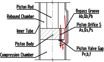
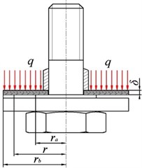
Fig. 2Mechanical model of throttle slice
3. Bend deform differential equation for ALDUUL
Fig. 2 shows the mechanical model of throttle slice of the foot valve which are made of only annular elastic throttle slice. The boundary conditions of throttle slice are fixed restriction at the inner radius, and free restriction at the outside radius. To the throttle slice, is the inner radius (fixing dimension is considered), is the outside radius, is the thickness of the throttle slice, is the pressure, and is the deformation at any radius .
Build the bipolar coordinates by the throttle slice circle center. Being symmetrical about the axis, according to the basic principles in the elastic mechanics, the differential equation of elastic throttle slice deformation is established as [14-16]:
where, is the any radius of throttle slice; ; is Poisson ratio of throttle slice; is the elasticity coefficient of material of throttle slice.
Therefore, the bending deformation formula for ALDUUL when the radius is can be obtained by solving the Eq. (9) as:
where is the odd general solution of Eq. (11); is the specific solution of the differential equation.
Because and have no relation with , on the assumption that the special solution of the differential equation is. So according to Eq. (9), the special solution of the differential equation is [16]:
Combine Eq. (11) and Eq. (12), the general solution of the differential equation is written as:
The boundary conditions of throttle slice are described as:
Inner circle: , 0.
Outside circle: , 0, where is the torque on throttle slice at radius ; is the shearing force on throttle slice at radius .
The constants in Eq. (13), , , and could be defined by the boundary conditions of throttle slice.
For 0, so:
For 0, so:
For 0, so:
For 0, so:
Combined Eqs. (14)-(17), the coefficient of the general solution of throttle slice deformation differential equation is:
With:
Therefore, the deformation for ALDUUL when the radius is can be obtained by Eqs. (13), (18) and (19).
4. Oil flow mechanisms in the VSA and dynamics analysis
Fig. 3 shows the VSA designed in this study. The bypass groove is added in the inner tube with a width of 1-2 mm, a depth of 0.25-1.25 mm and a length of 10-60 mm. The out characteristics of the VSA can change with different driving conditions, in a normal driving mode, the piston reciprocating motion within the range of the bypass groove, the damping force is reduced, and comfort is improved; while in an abnormal driving mode (e.g. sharp turn), The piston movement range is larger than the bypass groove, the damping force is added, and safety is improved.
The oil flowing at the rebound stroke can be divided into three flows. The first one is a flow which flows from the reservoir chamber to the compression chamber through the foot valve system, the oil at the foot valve system in turn passes through suction orifice and the suction valve. The pressure difference of suction orifice is , and the pressure difference of the suction valve is . The others are the flow which flow from the rebound chamber to the compression chamber through the piston valve system and bypass groove respectively. The flow at the piston valve system in turn passes through rebound orifice and rebound valve notch or rebound valve gap. The pressure difference of the rebound orifice is , and the pressure difference of rebound valve notch and the rebound valve gap are and respectively. A part of the oil flows back to the compression chamber through the bypass groove and its pressure difference is .
Fig. 3Schematic diagram of the oil flow and pressure difference of rebound stroke and compression stroke
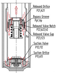
a) Rebound stroke
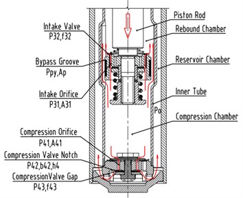
b) Compression stroke
The oil flowing at the compression stroke can also be divided into three flows. The first one is a flow which flows from the compression chamber to the reservoir chamber through the foot valve system. The flow at the foot valve system in turn passes through the compression orifice and compression valve notch or compression valve gap. The pressure difference of the compression orifice is , and the pressure difference of the compression valve notch and the compression valve gap are and respectively. The others are the flow which flow from the compression chamber to the rebound chamber through the piston valve system and bypass groove respectively. The flow at the piston valve system in turn passes through the intake orifice and the intake valve. The pressure difference of the intake orifice is , and the pressure difference of the intake valve is . A part of the oil flows back to the rebound chamber through the bypass groove and its pressure difference is .
4.1. Rebound stroke
is the piston velocity, is the piston sectional area, and is the piston rod sectional area. During the rebound stroke, is the flow rate from the reservoir chamber to the compression chamber through the foot valve system; is the flow rate from the rebound chamber to the compression chamber through the piston valve system and the bypass groove. So, and can be expressed as:
4.1.1. Calculating pressure difference of the foot valve system at rebound stroke
The total pressure difference of the foot valve system at rebound stroke can be expressed as:
where: is the suction orifice sectional area of the foot body, is the suction orifice number of the foot body, , are inside and outside radius of the top groove of the foot body respectively, , are inside and outside width of the top groove of the foot body respectively, is the suction valve opening. is force area of the intake valve, is spring stiffness of the intake valve, is spring preload of the intake valve.
can be obtained by solving Eq. (20) and Eqs. (22)-(25).
4.1.2. Calculation of pressure difference for the piston valve system at rebound stroke
At the rebound stroke, is the flow rate through the piston valve system, is flow rate through the bypass groove, so, (if the piston is located outside the bypass groove, 0), then the oil flow belongs to the SPCPL.
The total pressure difference of the piston valve system can be expressed as:
where: is the rebound orifice sectional area, is the rebound orifice number, is the height of rebound valve notch, is the width of the bottom embossing on the piston body, is the total length of the rebound valve notch.
When the rebound valve is open, the flow of the rebound valve is gap flow, its equation can be expressed as:
is force area of the rebound valve, is the inside circumference of the embossing on the piston body. is the rebound valve opening, is the spring stiffness of the rebound valve, is spring preload of the rebound valve.
Where, when the rebound valve is not open, 0.
Combined Eq. (26)-(30), the total pressure difference of the piston valve system only depends on the flow rate if the structural parameters of the VSA are fixed. The function expression between and can be obtained by polynomial fitting as follows:
The pressure difference of inside the bypass groove is:
where is the bypass groove number, is the bypass groove sectional area.
And:
Combine Eq. (21) and Eq. (31)-(33), the total pressure difference of the piston valve system can be obtained.
The total damping force at rebound stroke of the VSA can be expressed as:
where, is the friction force acting on the piston rod, and is the air pressure of the reservoir chamber.
4.2. Compression stroke
During the compression stroke, is the flow rate from the compression chamber to the rebound chamber through the piston valve system and the bypass groove, is the flow from the compression chamber to the reservoir chamber through the foot valve system. So:
4.2.1. Calculating pressure difference of the piston valve system at compression stroke
During the compression stroke, is the flow rate through the piston valve system, is the flow rate through the bypass groove, so (if the piston is located outside the bypass groove, 0), then the oil flow belongs to the SPCPL.
The total pressure difference of the piston valve system can be expressed as:
where: is the intake orifice sectional area of the piston body, is the intake orifice number of the piston body, , are inside and outside radius of the top groove of the piston body respectively, , is inside and outside width of the top groove of the piston body respectively. is force area of the intake valve, is the intake valve opening, is the spring stiffness of the intake valve, is spring preload of the intake valve.
Combined Eqs. (37)-(40), the total pressure difference of the piston valve system only depends on the flow rate if the structural parameters of the VSA are fixed. The function expression between and can be obtained by polynomial fitting as follows:
The pressure difference of inside the bypass groove is:
and:
The total pressure difference can be obtained by solving Eq. (35) and Eq. (37)-(43).
4.2.2. Calculating pressure difference of the foot valve system at compression stroke
During the compression stroke, the total pressure difference of the foot valve system can be expressed as:
where: is the sectional area of the compression orifice, is the compression orifice number, is the foot valve opening, is the height of the compression valve notch, is the width of the embossing of the foot body, is the total length of the compression valve notch, is the inside circumference of the embossing of the foot body. When the compression valve is not open, 0.
Based on the structural parameters of the foot valve system, the relationship between and can be solved by Eq. (13), and the detail expression as follows:
Then can be obtained by solving the Eqs. (44)-(48). The total damping force at compression stroke of the VSA can be expressed as:
5. Outer characteristic simulation of the VSA based on MATLAB/Simulink
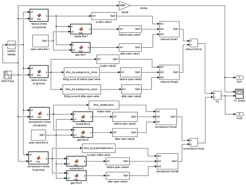
Outer characteristic simulation model of the VSA is established by MATLAB/Simulink software for rebound stroke, compression stroke, inside and outside the bypass groove. Which is shown in Fig. 4.
Fig. 4Outer characteristic Simulink model of the VSA
6. Results and discussion
According to the shock absorber bench test standard, sinusoidal excitation is used to test the VSA. The main physical parameters of the VSA are listed in Table 1.
6.1. Force-stroke curve
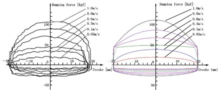
Fig. 5(a) shows the experimental and simulation results of F-S curve when the piston is outside the bypass groove, and its stroke is 40 mm. Fig. 5(b) shows the experimental and simulation results of F-S curve when the piston is inside the bypass groove, and its stroke is 30 mm. Fig. 5(c) shows the experimental and simulation results of F-S curve when the piston stroke is inside the bypass groove and outside the bypass groove, and its stroke is 80 mm.
Table 1Physical parameters of the VSA
Parameters | Value |
Diam. of piston rod | ø18 mm |
Diam. of piston | ø27 mm |
Width of bypass groove | 1.5 mm |
Depth of bypass groove | 1.0 mm |
Length of bypass groove | 40 mm |
Number of bypass groove | 2 |
Compression valve | 3.5 mm |
Compression valve | 7.25 mm |
Suction valve spring reload | 4.5 N |
Intake valve spring reload | 4.0 N |
Equivalent thickness of compression valve | 0.217 mm |
Rebound orifice (number×inner Diam.) | 3× ø1.5 mm |
Compression orifice (number×inner Diam.) | 4× ø1.5 mm |
Suction orifice (number×inner Diam.) | 6× ø3 mm |
Intake orifice (number×inner Diam.) | 6× ø3 mm |
Rebound valve notch (number×width) | 1×2 mm |
Compression valve notch (number×width) | 3×2 mm |
Fig. 5F-S curve of experimental and simulation
a) F-S curve of outside the bypass groove (40 mm)
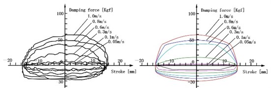
b) F-S curve of inside the bypass groove (30 mm)
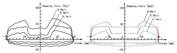
c) F-S curve of inside the bypass groove and outside the bypass groove (80 mm)
Two important conclusions can be found from Fig. 5: One is the F-S curves of three conditions are normal and its distortions are avoided. Another is the damping force at the rebound and compression stroke is almost consistent with experiment results, and the error is minor. It proves that the mathematical model is correct and reliably, which is based on many theories, such as the calculating ways of the embranchment flow rate and the throttle pressure difference on the SPCPL, the equation for ALDUUL, pipeline flow, nozzle flow and gap flow.
6.2. Force-velocity curve
When the piston velocity range is 50-800 mm/s, F-V curves of experiment and simulation are obtained by simulating inside the bypass groove and outside the bypass groove respectively. Fig. 6 shows the results.
Fig. 6F-V curve of experimental and simulation inside bypass groove and outside bypass groove
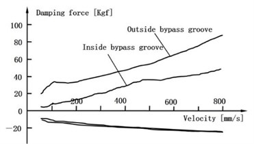
a) Experimental results
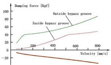
b) Simulation results
Fig. 6 shows that the damping force increases with the growing of the piston velocity, and the VSA has two kinds of damping force modes according to the piston position: soft and hard mode. The simulation result agrees well with the experiment result. It proves that the mathematical model is reliable and accurate enough.
7. Sensitivity analysis of bypass groove diameter on damping force
In order to apply the model to engineering design and predict the outer characteristic of the VSA, the effect of the bypass groove diameter on damping force is studied when piston is inside the bypass groove. Fig. 7 shows the results.
Fig. 7Sensitivity of bypass groove diameter on damper force
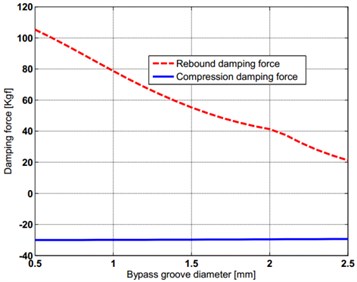
a) Effect of bypass groove diameter on damping force
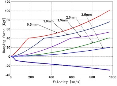
b) Effect of bypass groove diameter on F-V curve
Through simulating the effect on damping force which is caused by the bypass groove diameter, the following conclusions are obtained:
1) Fig. 7(a) shows the bigger bypass groove diameter, the smaller damping force of the VSA, and the bypass groove have greater effect on rebound damping force than compression damping force.
2) When the inside diameter of the bypass groove is a constant, Fig. 7(b) shows the higher piston velocity, the greater effect on damping force of the bypass groove diameter becomes. The bigger bypass groove diameter the higher opening velocity of the rebound valve will be, but the effect on opening velocity of compression valves is very little.
8. Discussion
The factors such as oil temperature, oil viscosity, oil flow characteristics and internal wear of the shock absorber will affect its output result. However, this article assumes that the above factors have not changed when the shock absorber runs, so that reduce the complexity of the mathematical model. Although the calculated results have good consistency with the experimental results in the premise of hypothesis, the mathematical model of this paper needs to be tested in the future practical application for the sake of academic rigor, and summarize the influence degree of the influence factors that are assumed to be constant on the calculation results.
9. Conclusions
In this study, the methods of calculating throttle pressure and the embranchment flow rate on the SPCPL is deduced, and the detailed mathematical model of the VSA is established by using these methods and the equation for ALDUUL. Many theories are used in the model, such as pipeline flow, nozzle flow and gap flow. The simulation of the VSA is performed by MATLAB/Simulink software and its results are agree with the experimental results to prove the correct and reliable of the mathematical model. By using the mathematical model, the sensitivity on damping force has been specifically analyzed, which is caused by the structural parameters of the bypass groove. Taking these complicated factors into account, the description of the VSA damping characteristic is more accurate, and the rule of physical properties and structural features can be described more exactly. Such results can also be served as the reference for the design of the VSA and the prediction of its performance.
References
-
Sung Kum-Gil, Han Young-Min, Cho Jae-Wan, ChoiSeung-Bok Vibration control of vehicle ER suspension system using fuzzy moving sliding mode controller. Journal of Sound and Vibration, Vol. 311, 2008, p. 1004-1019.
-
Choi Seung-Bok, Han Young-Min, SungKum-Gil Vibration control of vehicle suspension system featuring ER shock absorber. International Journal of Applied Electromagnetics and Mechanics, Vol. 27, 2008, p. 189-204.
-
Sung K.-G., Han Y.-M., Sohn J. W., Choi S.-B. Road test evaluation of vibration control performance of vehicle suspension featuring electrorheological shock absorber. Proceedings of the Institution of Mechanical Engineers, Part D: Journal Automobile Engineering, Vol. 222, 2008, p. 685-698.
-
Yoon Young Hwan, Choi Myung Jin, Kim Kyung Hoon Development of a reverse continuous variable damper for semi-active suspension. International Journal of Automotive Technology, Vol. 3, Issue 1, 2002, p. 27-32.
-
Nicolas C. F., Landaluze J., Sabalza X., Reyero R. An intelligent suspension system based on a continuously variable shock absorber. AVEC’96-International Symposium on Advanced Vehicle Control, 1996, p. 241-254.
-
Dixon John C. The Shock Absorber Handbook. 2nd Edition, Professional Engineering Publishing Ltd and John Wiley and Sons, 2007.
-
Wren R., Zhang J., Jin G. The virtual tuning of an automatic shock absorber. Proceedings of the Institution of Mechanical Engineers, Part C: Journal Mechanical Engineering Science, Vol. 223, 2009, p. 2655-2662.
-
Lee Choon Tae Simulation and experimental validation of vehicle dynamic characteristics for displacement sensitive shock absorber using fluid-flow modeling. Mechanical Systems and Signal Processing, Vol. 20, 2006, p. 373-388.
-
Lee Choon Tae Study of the Simulation model of a displacement-sensitive shock absorber of a vehicle by considering the fluid force. Journal of Automobile Engineering, Vol. 219, Issue 8, 2005, p. 965-975.
-
Lee C. T., Moon B. Y. Simulation and experimental validation of vehicle dynamic characteristics for displacement-sensitive shock absorber using fluid-flow modelling. Mechanical Systems and Signal Processing, Vol. 20, 2006, p. 373-388.
-
Calvo J. A., Lopez Boada B., San Roman J. L. Influence of a shock absorber model on vehicle dynamic simulation. Proceedings of the Institution of Mechanical Engineers, Part D: Journal Automobile Engineering, Vol. 223, 2009, p. 189-202.
-
Pracny V., Meywerk M., Lion A. Hybrid neural network model for history-dependent automotive shock absorbers. Vehicle System Dynamics, Vol. 45, Issue 1, 2007, p. 1-14.
-
Shamsi A., Choupani N. Continuous and discontinuous shock absorber control through skyhook strategy in semi-active suspension system (4DOF Model). Industrial and Aerospace Engineering. World Academy of Science, Engineering and Technology International Journal of Mechanical and Mechatronics Engineering, Vol. 2, Issue 5, 2008, p. 254-258.
-
Xu Z.-L. Elasticity Mechanics Course of Study. Higher Education Press, Beijing, 2002, (in Chinese).
-
Changcheng Zhou, Leilei Zhao, Yanhui Cai Function modeling and simulation of deformation of multi-throttle-slices for telescopic shock absorber. International Conference on Automation and Logistics Shenyang, China, 2009, p. 1441-1444.
-
Changcheng Zhou, Canchang Liu, Leilei Zhao deformation analytic computation of throttle slice of shock absorber. International Conference on Computational Intelligence and Natural Computing, 2009, p. 359-361.
About this article

The study was supported by the Specialized Research Fund for Science and Technology Research Project of Chongqing Municipal Education Commission (Grant No. KJ1403005) and 2014 Annual Task for “Twelfth Five-Year Plan” of Chongqing Municipal Education Science (Grant No. 2014-GX-128) and Science and Technology Plan Projects of Chongqing Yubei District (Grant No. 2016 Social (15)).
