Abstract
In order to effectively improve safety and stability during transportation, a shock absorber with buffering and self-locking functions was designed. Based on the rigid flexible coupling technology, the working state and dynamic response of the shock absorber were simulated and analyzed. The linear spring was treated as a flexible body, and the cam button, guide pillar, and base were treated as rigid bodies. The modal neutral files required for the rigid flexible coupling dynamic analysis were generated. Based on ADAMS, a dynamic simulation model was established, replacing a part of the rigid model with a flexible model and conducting load response analysis on it. To further improve the vibration reduction effect, the performance of the contact material of the shock absorber was analyzed. Through the calculation of dynamic characteristics, it could be known that the self-locking mechanism had no dead points, and the vibration reduction force response stability was high, meeting the working requirements.
Highlights
- The modal neutral files required for the rigid flexible coupling dynamic analysis were generated.
- Based on ADAMS, a dynamic simulation model was established, replacing a part of the rigid model with a flexible model and conducting load response analysis on it.
- To further improve the vibration reduction effect, the performance of the contact material of the shock absorber was analyzed.
1. Introduction
For special equipment, the transportation distance is long, and the loading and transportation process may cause damage to the container [1]. The design needs to ensure the integrity of the containment boundary of the transport container in the event of a serious accident, taking into account the impact, collision, and other factors on the transport container to avoid radioactive material leakage [2-4]. Therefore, the design of shock absorber for spent fuel transport containers is extremely critical. The function of shock absorber is to ensure that transportation containers can absorb energy when subjected to external load impacts, alleviate the impact of impact loads on the contents of the container, and ultimately ensure the integrity of the container's containment boundary [5]. As a key component, shock absorber are mainly composed of internal filling materials and wrapped springs, which must have certain strength and plasticity, while meeting the characteristics of support protection and shock absorption.
At present, most shock absorber cannot meet the self-locking function and require multiple springs to achieve the action of the mechanism [6]. Multiple springs increase the complexity of the mechanism, and the rigid flexible coupling dynamic model has not been used to study the motion characteristics and operating forces of the cam self-locking mechanism [7, 8]. Based on this, this article proposes a mechanism that achieves press self-locking through the combination of wire spring deformation and cam sliding groove, and conducts a rigid flexible coupling dynamic analysis to verify the feasibility of mechanism motion and the effectiveness of self-locking function. Using the dynamic simulation results of the wire spring, quickly locate the low cycle fatigue danger point position of the structure, and analyze the reliability of the wire spring parts based on the stress strength interference theory. In order to further improve transportation safety, a mechanism that achieves press self-locking through the combination of wire spring deformation and cam sliding groove was proposed, and its rigid flexible coupling dynamics analysis was carried out to analyze the feasibility of mechanism motion and the effectiveness of self-locking function. Through dynamic simulation results, it is possible to quickly locate the low-cycle fatigue risk points of the structure, and verify the reliability of the shock absorber based on stress strength interference theory.
2. Structural design and dynamic modeling of self-locking shock absorber
2.1. Structural design and functional analysis
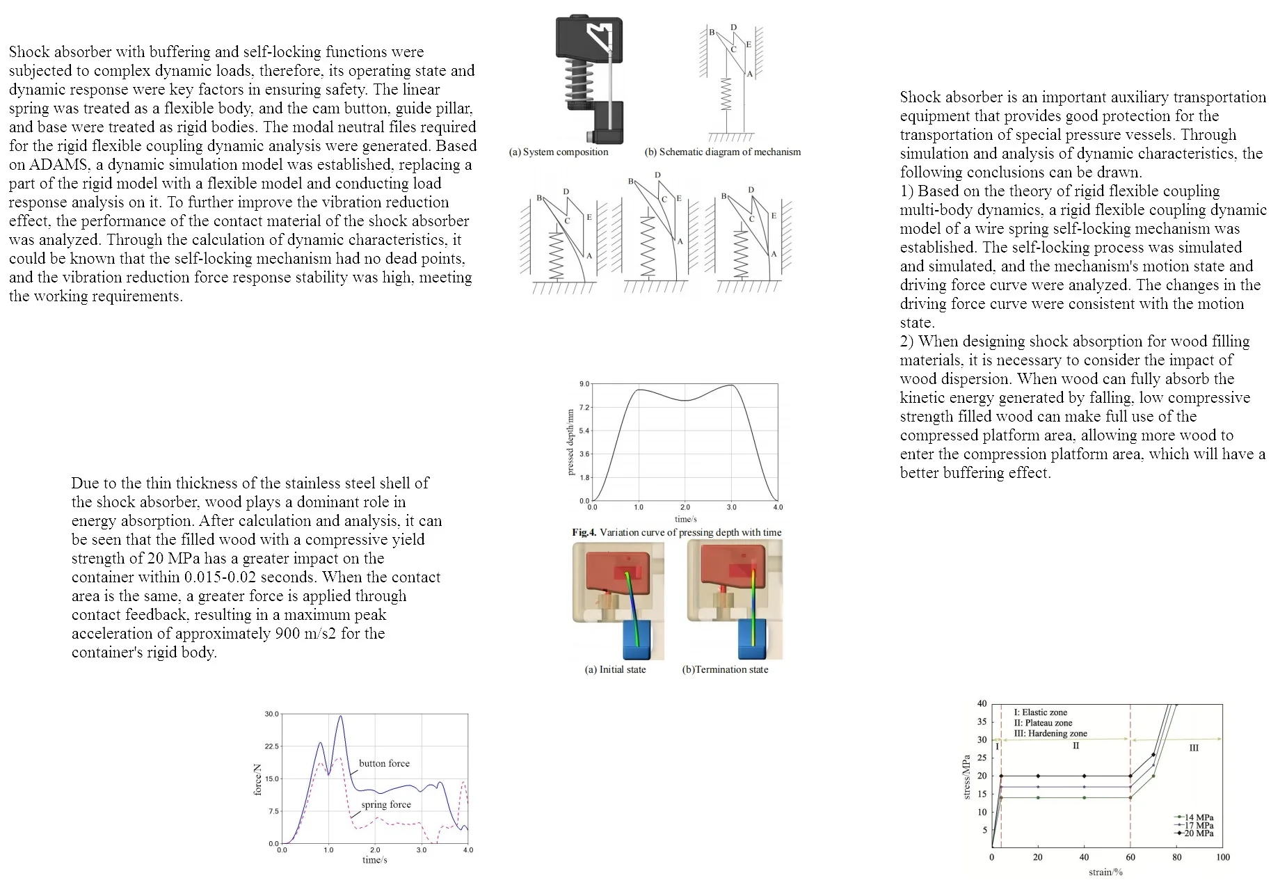
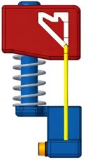
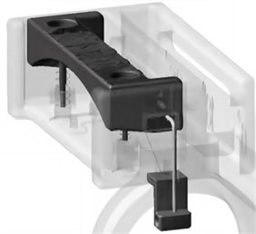
The working principle of the self-locking mechanism is mainly that the cam button moves downward along the axial direction of the guide column, causing the short edge of the wire spring to move in the sliding groove of the cam button, and lock when it reaches the self-locking position of the sliding groove. The shock absorber cam button, guide pillar, compression spring, wire spring, and base are composed, as shown in Fig. 1. The motion state of shock absorber is shown in Fig. 2. The cam button moves downward under the pressure of the operator, and the contact point between the short side of the wire spring and the cam button moves from the initial point A to the intermediate point B. When the button moves down, the operator releases the pressing pressure, and the cam button is lifted under the action of pressure spring force. Under the action of lateral elastic force of wire spring, the contact moves from intermediate point B to intermediate point C, and the cam button reaches the locking position. Under the action of lateral elastic force of wire spring, press the cam button again. The contact moves from intermediate point C to intermediate point D. Lift the cam button, the contact moves from the middle point D to the middle point E under the action of the lateral elastic force of the wire spring, and then returns to the initial point A across the small angle bevel, and presses into the chute under the action of the forward elastic force of the wire spring. There is a height difference between the start point and the low angle ramp. In the case of mechanical vibration or impact, due to its self-locking characteristics, this type of shock absorber can effectively prevent loosening and detachment. This ability is very important for most transported equipment, especially in long-term road transportation situations. Due to its self-locking ability, it does not require manual shaking of tools such as wrenches, saving time and labor.
Fig. 1Composition of shock absorber mechanism
a) System composition
b) Schematic diagram of mechanism
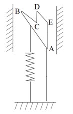
Fig. 2Different states of shock absorber
2.2. Establishment of virtual prototype model
In the working process of shock absorber, the wire spring experiences bending and torsion deformation, while the deformation of other parts such as cam button can be ignored basically. Therefore, the wire spring can be regarded as flexible body, and the cam button, guide post and base can be regarded as rigid body to establish the rigid-flexible coupling dynamic model, as shown in Fig. 3. Introduce the wire spring model into ANSYS, create a hexahedral mesh element, the mesh type is Solid185, and complete the mesh division of the whole wire spring with Sweep method. The wire spring material is defined as the stainless steel spring wire material, and the connection part with the base is defined as the rigid area. The Craig-Bampton mode synthesis method is used to extract the first 6 modes of the wire spring to generate the modal neutral file required for the rigid-flexible coupled dynamic analysis. Then, portions of the ADAMS rigid model are replaced with modal neutral files and rigidly attached to the base. Establish the button sliding pair and contact setting, define the friction contact between the wire spring and the cam button, and the Coulomb friction coefficient is 0.1.
Fig. 3Virtual prototype model
3. Simulation and analysis of dynamic characteristics
3.1. Motion state analysis
In order to accurately analyze the working process of the wire spring mechanism, the driving sliding pair simulates the hand pressing operation, and the driving mode is shown in Fig. 4. Under this driving condition, the motion process of the established dynamic simulation model of the linear spring damping mechanism is basically consistent with the expected motion process. The state cloud diagram of the initial and termination states is shown in Fig. 5. Press the button to the bottom and lift it, the short side of wire spring moves from section AB to point C and completes self-locking. Press the button again for 2-4 s, the short side of the wire spring is removed from the C point and returned to the original position again, the self-locking mechanism is unlocked and the button is reset.
Fig. 4Variation curve of pressing depth with time
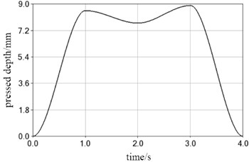
Fig. 5Motion state of shock absorber mechanism
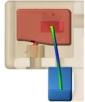
a) Initial state
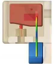
b) Termination state
3.2. The influence of size on support stress
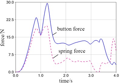
During the downward movement of the button, in addition to overcoming the elastic force of the compression spring, it also needs to overcome the normal force and contact friction force of the line spring acting on the cam groove. The driving force of the mechanism button and the force curve of the wire spring are shown in Fig. 6. As shown in the figure, during the downward movement of the button, the button pressure undergoes sudden changes in driving force at points B, C, D, and E. Due to the short side of the wire spring being at point B, sliding from slot AB into slot BC instantly reduces the bending angle of the long side of the wire spring. The normal contact force and friction force between the short edge of the wire spring and the cam groove instantly decrease. At point C, the contact curve between the short edge of the wire spring and the cam groove changes from BC groove to CD groove, and the contact force and friction force are further reduced. At point D, the contact curve between the short edge of the wire spring and the cam groove changes from BC groove to DE groove, and the lateral bending force of the short edge of the wire spring will be 0. At point E, due to the inclined surface of the cam groove, the button bears the dynamic friction force caused by the positive elasticity of the wire spring. During the entire pressing process, the pressure should not exceed 30N, which can meet the operational ability.
Fig. 6The curve of pressure over time
3.3. Optimization of vibration reduction characteristics
In order to further reduce rigid contact, wooden connections were used between the shock absorber and the load-bearing container. The dispersibility of wood directly affects its compressive strength, and the absorption capacity of wood is closely related to the envelope area of the wood compression stress-strain curve, which is a key parameter of shock-absorbing materials. The platform stage determines the transportation capacity of wood. The wood batch used for shock absorber was selected, and after 20 sets of tests, the compression strain curve of the wood was relatively dispersed. The average compressive yield strength of wood is 17 MPa, with a standard deviation of 3MPa. As shown in Fig. 7, the specific deformation energy dispersion of the sample is not significant, so it can be ignored. Therefore, three curves with compressive yield strengths of 14, 17, and 20 MPa were selected for numerical simulation calculation to compare the effect of wood with different compressive yield strengths on the rigid body acceleration of transport container cylinders. Due to the thin thickness of the stainless steel shell of the shock absorber, wood plays a dominant role in energy absorption. After calculation and analysis, the filled wood with a compressive yield strength of 20 MPa has a greater impact on the container within 0.015-0.02 seconds. When the contact area is the same, a greater force is applied through contact feedback, resulting in a maximum peak acceleration of approximately 900 m/s2 for the container’s rigid body. The feedback force of filled wood with a compressive yield strength of 14 MPa is smaller than that of filled wood with a yield strength of 20 MPa, and the peak acceleration of the container's rigid body is the smallest, about 800 m/s2. Obviously, when the shock absorber has sufficient energy absorption, filling wood with a compressive strength of 14 MPa has the best buffering effect. By using more compression strokes to reduce the impact of falling on the container body, the platform area of wood compression is fully utilized. Due to the absorption of energy by the higher yield strength platform, filled wood with a compressive strength of 20 MPa has a smaller compression stroke than filled wood with a compressive strength of 14 MPa. The compression platform area of wood is not fully utilized, or more wood areas are not compressed.
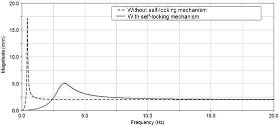
In order to compare and analyze the dynamic response between conventional shock absorbers and optimized self-locking mechanism shock absorbers, spectral response analysis was conducted separately, and the results are shown in Fig. 8. It can be seen that compared to conventional shock absorber, shock absorber with self-locking mechanisms have a certain increase in natural frequency and can more effectively reduce low-frequency vibration. By optimizing the vibration damping support, the maximum amplitude can be reduced by more than 70 %, and the improvement effect on vibration response is significant.
Fig. 7Compressive stress-strain curve
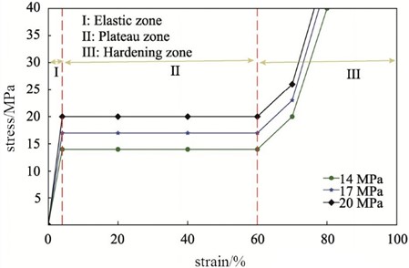
Fig. 8Comparison of amplitude frequency response of different shock absorber
4. Conclusions
Shock absorber is an important auxiliary transportation equipment that provides good protection for the transportation of special pressure vessels. Through simulation and analysis of dynamic characteristics, the following conclusions can be drawn.
1) Based on the theory of rigid flexible coupling multi-body dynamics, a rigid flexible coupling dynamic model of a wire spring self-locking mechanism was established. The self-locking process was simulated and simulated, and the mechanism’s motion state and driving force curve were analyzed. The changes in the driving force curve were consistent with the motion state.
2) When designing shock absorption for wood filling materials, it is necessary to consider the impact of wood dispersion. When wood can fully absorb the kinetic energy generated by falling, low compressive strength filled wood can make full use of the compressed platform area, allowing more wood to enter the compression platform area, which will have a better buffering effect.
References
-
Rahul K., “Dynamic modeling and analysis of a hydro-mechanical power transmission system,” Materials Today: Proceedings, Vol. 61, No. 1, pp. 50–54, 2022, https://doi.org/10.1016/j.matpr
-
J. Ren, Q. Li, Z. Ren, and G. Yang, “A new hydraulic damper dynamics model and the availability on high-speed vehicle dynamics investigation,” Vehicle System Dynamics, Vol. 61, No. 1, pp. 356–374, Jan. 2023, https://doi.org/10.1080/00423114.2022.2053728
-
Y. K. Rashidov, J. T. Orzimatov, K. Y. Rashidov, and Z. X. Fayziev, “The method of hydraulic calculation of a heat exchange panel of a solar water-heating collector of a tube-tube type with a given nonuniform distribution of fluid flow along lifting pipes,” Applied Solar Energy, Vol. 56, No. 1, pp. 30–34, May 2020, https://doi.org/10.3103/s0003701x20010107
-
A. Daşdemir, “A modal analysis of forced vibration of a piezoelectric plate with initial stress by the finite-element simulation,” Mechanics of Composite Materials, Vol. 58, No. 1, pp. 69–80, Mar. 2022, https://doi.org/10.1007/s11029-022-10012-7
-
V. Santos Arconada and J. García-Barruetabeña, “Development and validation of a simplified nonlinear dynamic model of a passive twin-tube hydraulic shock absorber,” Journal of Vibration and Control, Vol. 27, No. 15-16, pp. 1724–1735, Aug. 2020, https://doi.org/10.1177/1077546320947955
-
V. Nicoletti, R. Martini, L. Amico, S. Carbonari, and F. Gara, “Operational modal analysis for supporting the retrofit design of bridges,” Ce/papers, Vol. 6, No. 5, pp. 1182–1188, Sep. 2023, https://doi.org/10.1002/cepa.2125
-
M. Sohrabifard, M. Nategh, and M. Ghazavi, “Evaluation, calibration, and modal analysis for determination of contact stiffness between workpiece and components of milling fixture,” Proceedings of the Institution of Mechanical Engineers, Part B: Journal of Engineering Manufacture, Vol. 237, No. 12, pp. 1819–1835, Nov. 2022, https://doi.org/10.1177/09544054221138165
-
Al-Maliky and Salam J. Bash, “Effect of suction pipe diameter and submergence ratio on air lift pumping rate,” Advanced Materials Research, Vol. 1036, No. 1, pp. 703–707, Oct. 2014, https://doi.org/10.4028/www.scientific.net/amr.1036.703
About this article

The authors have not disclosed any funding.
The datasets generated during and/or analyzed during the current study are available from the corresponding author on reasonable request.
The authors declare that they have no conflict of interest.
