Abstract
The dual-rotor system is the core component of advanced aero-engine. Establishing a reasonable, accurate, and efficient dynamics model is the key to studying the dynamics and vibration of the rotor system for aero-engine. This manuscript takes a representative aircraft engine dual-rotor system as a prototype, considers the rig-id-flexible coupling characteristics of different stiffness elastic supports and rotor structures, and establishes an analytical dynamic model of the dual-rotor system. Based on the established dynamic model, the natural char-acteristics of the dual-rotor system are analyzed. The model was validated using two different research methods: the rigid-flexible coupling multi-body system dynamics simulation platform ADAMS, and finite element analy-sis. The dynamic model of the dual-rotor system established in this paper can meet the requirements of hierar-chical rigid-flexible coupling of system and structure, overall mass distribution, and stiffness distribution. In particular, it can also effectively realize the simulation of multi-facet and multi-phase unbalanced vibration of the rotor system. The research methods of this paper can further enrich the basic theory of dynamics and vibration of the aero-engine rotor system.
Highlights
- The dual-rotor system is the core component of advanced aero-engine
- Accurate dynamic model is the key to correctly predict rotor system vibration
- Elastic strain energy will be excessively introduced for parts with high stiffness under elastic assumption
- Rigid-flexible coupling model can more accurately express the dynamic characteristics of aero-engine dual-rotor system
1. Introduction
The dual-rotor system of aero-engine has multiple elastic supports, complex and special structures, and many factors are affecting its dynamic characteristics. Exploring a simplified model of the dual-rotor system that can reflect the structural characteristics and dynamic behavior of the aero-engine is the key to establishing an accurate and efficient dynamic model of rotor system for aero-engine. The model of the double rotors and multi-supports system used in the current research mainly includes the following types: the dual-rotor system with one disc for the high-pressure rotor and one disc for the low-pressure rotor [1-4], the dual-rotor system with two discs for the high-pressure rotor and two discs for the low-pressure rotor [5-7], and the dual-rotor system with multiple-discs [4, 8-10]. The rigid-flexible coupling of rotor system structure is not considered in dynamic modeling. When analyzing parts with large stiffness, the elastic strain energy will be too much included in the analysis based on the elastic hypothesis. The calculation error of the dynamics analysis and vibration prediction for the dual-rotor system is too large, so it is difficult to realize the accurate analysis and vibration prediction of the dynamic characteristics of an aero-engine rotor.
Aiming at the theoretical analysis requirements of dynamics and vibration characteristics of the dual-rotor system for aero-engine, considering multiple supports and the coupling of internal and external rotor structures, the energy method is used to establish an analytical dynamic model. The model has four lumped mass discs (low-pressure compressor, low-pressure turbine, high-pressure compressor, and high-pressure turbine) and five supports with different stiffness characteristics, and the low-pressure turbine shaft is considered as a flexible shaft. Based on the analytical model, the inherent characteristics of the dual-rotor system are analyzed and compared with the finite element results and multi-body dynamics simulation results, which verifies the effectiveness and accuracy of the analytical model. The accurate modeling of the dual-rotor system for aero-engine is realized, which lays a foundation for the subsequent vibration characteristics analysis of the dual-rotor system.
2. Dynamic modeling of the dual-rotor system
2.1. Mechanical model of the dual-rotor system
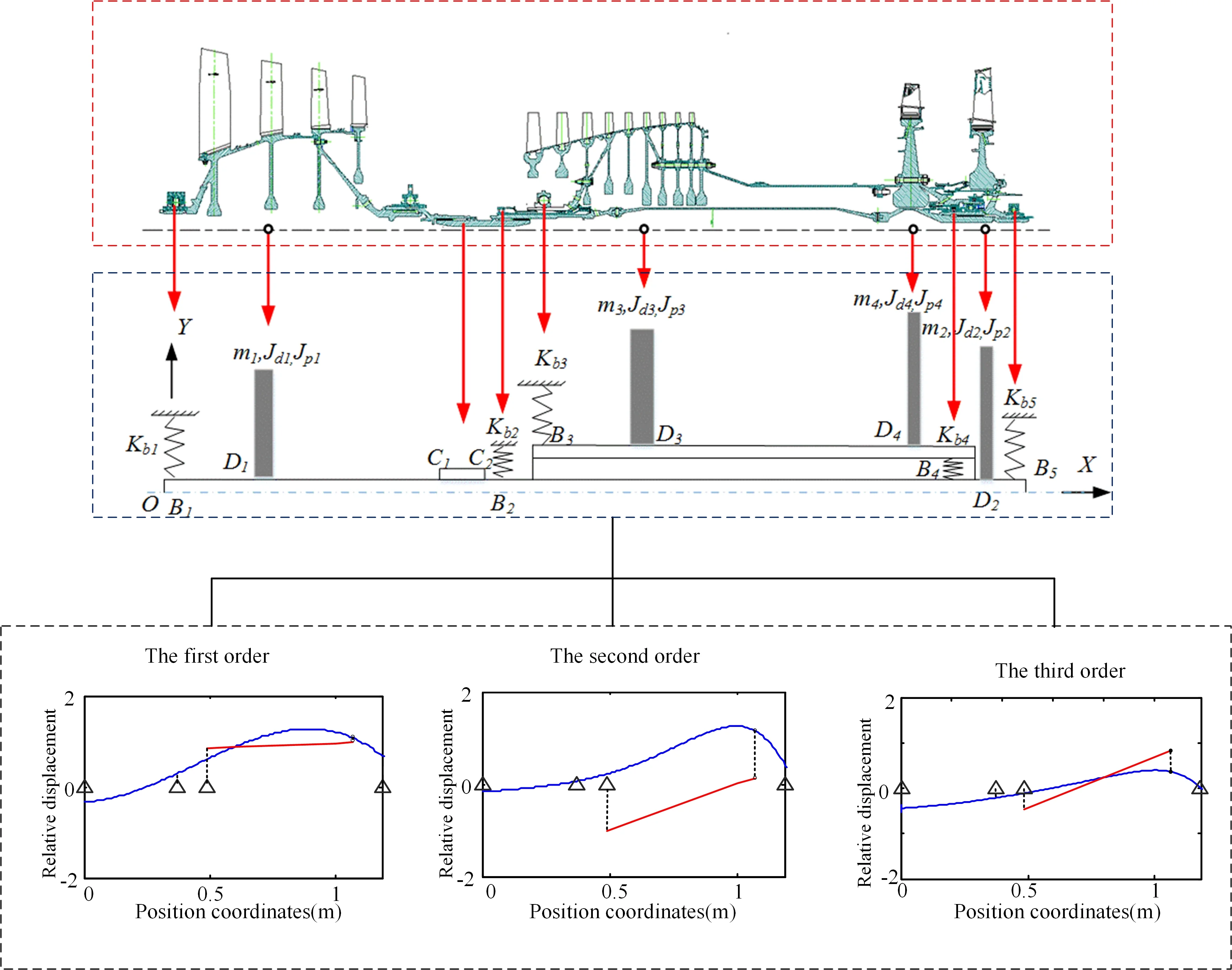
This section takes a typical aviation engine dual-rotor system as a prototype and establishes a simplified mechanical model of the dual-rotor system based on the principle of dynamic similarity. Through the qualitative study of the simplified model, this paper explores the important parameters that affect the regularity of the motion behavior of the system. According to the structure and working characteristics of the dual rotor system, a simplified model that can reflect the main dynamic behavior of the dual-rotor system for aero-engine is established, as shown in Fig. 1. The modeling process follows the dynamic similarity principle, and the obtained model has the same mass ratio as the prototype rotor system.
Fig. 1Simplified mechanical model of the dual-rotor system
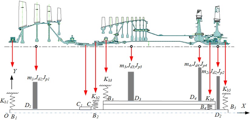
In the simplified model of the dual-rotor system, the compressor and turbine disc are simplified to a disc with equivalent mass and moment of inertia. The actual multi-disc structure is simplified into a few disc structures. The specific simplification method is as follows: the four-stage fan discs in the low-pressure rotor are simplified as disc D1 (LPC), the low-pressure turbine disc is equivalent to disc D2 (LPT), the nine-stage compressor discs of the high-pressure rotor is simplified as disc D3 (HPC), and the high-pressure turbine disc is equivalent to disc 4 (HPT).
The supports of the dual-rotor are simplified into five springs with different stiffness. The support stiffness , and are the combined equivalent stiffness of the bearing, squirrel cage and support at the front fulcrum of the fan rotor, the front fulcrum of the high-pressure rotor and the rear fulcrum of the low-pressure turbine respectively. is the combined stiffness of support 2 and support 3. The intermediate fulcrum adopts the same roller bearing as the prototype, and the stiffness is .
2.2. Rigid-flexible coupling dynamic model of the dual-rotor system
Taking the simplified model of the dual-rotor system shown in Fig. 1 as the research object, the motion analytical equation of the dual-rotor system is deduced with the help of the Lagrange method. The support is considered to be elastic and simulated with equivalent stiffness. The rotating speed of the rotating shaft is considered to be constant, and the disc, fan shaft, and high-pressure shaft are considered to be rigid. In particular, the elastic characteristics of the slender shaft of the low-pressure turbine are considered.
2.2.1. Kinetic energy of the dual-rotor system
The kinetic energy of the dual-rotor system includes the translational kinetic energy and rotational kinetic energy of the four discs, which can be recorded as follows:
where, and () are the translational kinetic energy and rotational kinetic energy of disc respectively.
Based on the method of establishing a coordinate system and determining the generalized displacement and velocity of the rotor system, the kinetic energy of the dual-rotor system is obtained. The mass, polar moment of inertia, and diameter moment of inertia of the rotor system are represented by , , and () respectively. The translational and rotational kinetic energy of turntables 1-4 are:
2.2.2. Potential energy of the dual-rotor system
The potential energy of the dual-rotor system is shown in Eq. (4), including the elastic potential energy of five fulcrums, the potential energy of the coupling and the elastic potential energy of the low-pressure turbine shaft:
It includes the elastic potential energy of five supports and the potential energy of coupling:
where, () is the displacement vector of the rotor pivot () in the generalized coordinate system. is the stiffness matrix of support ()
The elastic potential energy of the intermediate bearing is as follows:
Among them, and are the generalized displacement vectors of the intermediate support points on the high-pressure and low-pressure rotors, respectively. is the stiffness matrix of the intermediate support.
The elastic potential energy at the coupling is as follows:
where, and are the generalized displacement vectors at coupling connection points and , respectively. is the equivalent stiffness of the coupling.
Potential energy of the elastic shaft of a low-pressure turbine:
Among them, and are the forces acting on the low-pressure turbine shaft in the and directions. and are the torque of the low-pressure turbine shaft in the and directions. (, ) is the flexibility coefficient.
2.2.3. Dynamic equation of the dual-rotor system
The dynamic model of the dual-rotor system is established through the Lagrange equation:
where, () and () represents the distance between two points in Fig. 1, in units of m. , , , , , , . Additionally, is the distance between two points and. is the distance between two points and , expressed as . is the length of the coupling, expressed as . is the total length of the low-pressure turbine shaft, expressed as . and is the elastic modulus, in units of kg/(m·s2). and is the moment of inertia, in units of kg·m·s2.
3. The inherent characteristics of the dual-rotor system
Mastering the natural frequency and vibration mode is the basis of studying the dynamic response of the dual-rotor system. The inherent characteristics of the dual-rotor system are obtained based on the above dynamic Eq. (9).
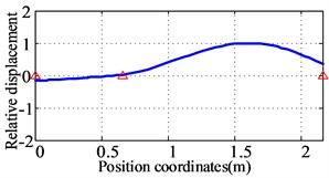
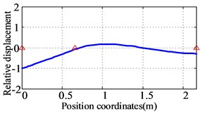
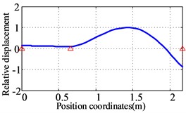
The first three natural frequencies and vibration modes of the simplified model are shown in Fig. 2. Campbell diagram is shown in Fig. 3, and the first two critical speeds are shown in Table 1.
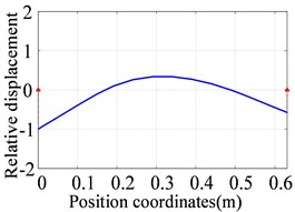
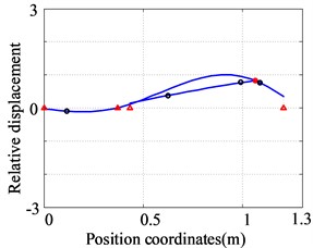
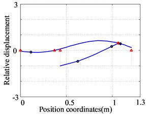
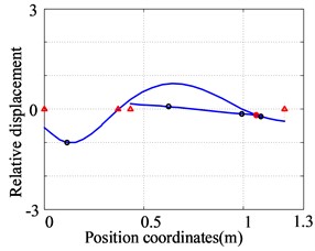
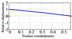
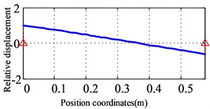
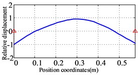
Fig. 2Analytical results for the first three orders natural frequencies and vibration modes of the dual-rotor system
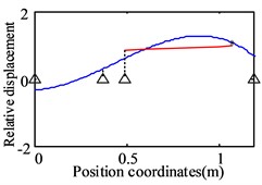
a) The first order (58.8 Hz)
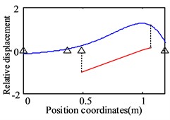
b) The second order (75.4 Hz)
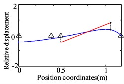
c) The third order (127 Hz)
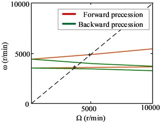
Table 1The first two critical speeds of the dual-rotor system
Order | The first order | The second order |
Value of the critical speeds | 3528 r/min | 4524 r/min |
It can be seen from Fig. 2 that the first vibration mode is represented by the bending of the low-pressure turbine rotor and the translation of the high-pressure rotor. The second vibration mode is characterized by the low-pressure turbine rotor bending and the high-pressure rotor pitching. The third-order modes are low-pressure fan rotor pitch, low-pressure turbine rotor bending, and high-pressure rotor pitch.
Fig. 3Campbell diagram for the dual-rotor system
4. Model validation
4.1. Model verification of the dual-rotor system based on multi-body dynamics
In this section, the analytical dynamic model of the dual-rotor system obtained in Section 2 is verified by the multi-body dynamics simulation analysis method. The rigid-flexible coupling simulation model of the dual-rotor system is carried out based on the software ADAMS, and the natural characteristics are analyzed. The results obtained by simulation are compared with the analytical results.
Based on the theory of multi-body dynamics, ADAMS can combine the mechanical boundary, load boundary, and geometric conditions of complex rotor systems for aero-engine in a concise simulation analysis model. ADAMS can realize the rigid-flexible coupling modeling of the aero-engine rotor system and can simulate the system motion and dynamic characteristics under actual working conditions. The rigid-flexible coupling simulation model of the aero-engine dual-rotor system is shown in Fig. 4.
Fig. 4Rigid-flexible coupling dynamic model of the dual-rotor system based on ADAMS
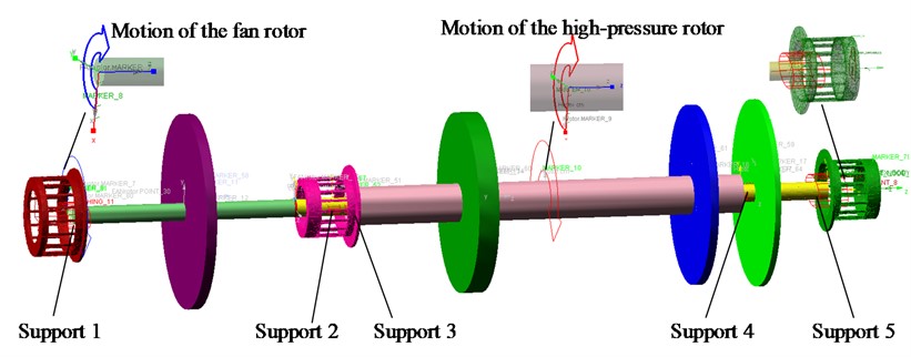
Where the low-pressure turbine shaft is set as a flexible body, and other components adopt the rigid assumption. The supports are defined by stiffness and damping, simulated by the "bushing" element. The coupling is simplified to a short shaft structure. The rotation of the dual-rotor system is realized by adding a drive to the center of the rotating shaft of the low-pressure rotor and the high-pressure rotor respectively.
The inherent characteristics of the dual-rotor system are calculated by the simulation method. The first three natural frequencies and vibration modes of the dual-rotor system are shown in Fig. 5.
Fig. 5The first three orders natural frequencies and vibration modes of the dual-rotor system based on ADAMS
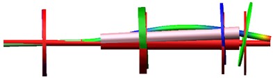
a) The first order (56.4 Hz)
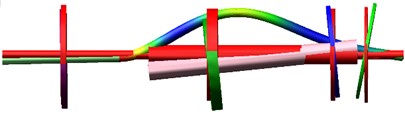
b) The second order (79 Hz)
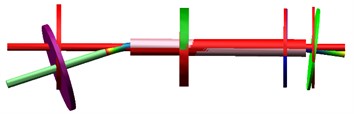
c) The third order (117.1 Hz)
The first vibration mode is represented by the bending of the low-pressure turbine rotor and the translation of the high-pressure rotor; The vibration mode is characterized by the low-pressure turbine rotor bending and the high-pressure rotor pitching. The third-order modes are low-pressure fan rotor pitch, low-pressure turbine rotor bending, and high-pressure rotor pitch. The first three modes are consistent with the results obtained in the previous Section 3 based on the analytical dynamic model.
4.2. Model verification of the dual-rotor system based on finite element method
In this section, the analytical dynamic model of the dual-rotor system obtained in section 2 is verified by the finite element method. The finite element model of the dual-rotor system is carried out, and the natural characteristics are analyzed. The results obtained by simulation are compared with the analytical results. In addition, the results of the dual-rotor system with four discs and five supports are compared with the prototype model.
Fig. 6Finite element model of the dual-rotor system with four discs and five supports
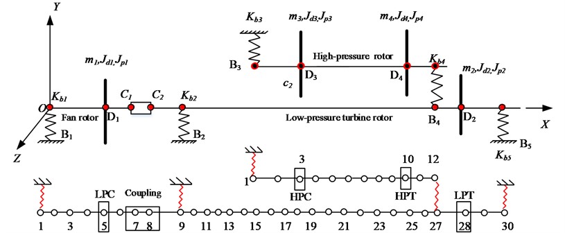
4.2.1. Finite element model of the dual-rotor system with four discs and five supports
During the establishment of the finite element model of the dual-rotor system, the following simplifications are made: (1) The shaft section is considered to be elastic. The mass and moment of the inertia of the shaft section are placed on the nodes at both ends. (2) The supports are considered as spring elements without cross stiffness and damping. (3) The fan disc, low-pressure turbine disc, high-pressure compressor disc, and high-pressure turbine disc are simplified as hollow discs, which are regarded as rigid bodies with rotation effects. It is concentrated at the center of the mass of each disc in the form of concentrated mass and moment of inertia.
The finite element model of the dual-rotor system is established, as shown in Fig. 6. The low-pressure rotor of the dual-rotor system with four discs and five supports is discretized with 30 nodes and 29 shaft segments. The high-pressure rotor system is discretized with 12 nodes and 11 shaft segments.
The first three natural frequencies and vibration modes of the low-pressure rotor system are calculated as shown in Fig. 7. The first vibration mode is the bending of the low-pressure turbine rotor. The second vibration mode is the bending of the fan rotor and the low-pressure turbine rotor. The third vibration mode is the bending of the low-pressure turbine section.
Fig. 7The first three orders natural frequencies and modes of the low-pressure rotor obtained by finite element method
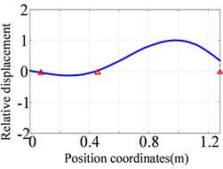
a) The first order (76.9 Hz)
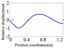
b) The second order (122.6 Hz)
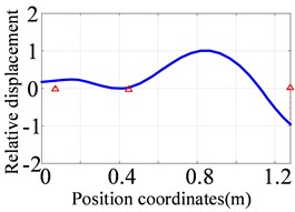
c) The third order (150.6 Hz)
Fig. 8The first three orders natural frequencies and modes of the high-pressure rotor obtained by finite element method
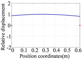
a) The first order (60.4 Hz)
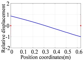
b) The second order (96.4 Hz)
c) The third order (388.2 Hz)
The first three natural frequencies and vibration modes of the high-pressure rotor are calculated as shown in Fig. 8. The first vibration mode is translational of the high-pressure rotor, the second vibration mode is the pitching of the high-pressure rotor, and the third vibration mode is the bending of the high-pressure rotor.
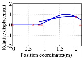
The first three natural frequencies and vibration modes of the dual-rotor system with four discs and five supports are obtained, as shown in Fig. 9. The first vibration mode is the bending of the low-pressure turbine rotor and the translational of the high-pressure rotor. The second vibration mode is the bending of the low-pressure turbine rotor and the pitching of the high-pressure rotor. The third vibration mode is the bending of the fan rotor and the low-pressure turbine rotor, the pitching of the high-pressure rotor.
Fig. 9The first three orders natural frequencies and modes of the dual-rotor system obtained by finite element method
a) The first order (55.9 Hz)
b) The second order (75.5 Hz)
c) The third order (122.0 Hz)
4.2.2. Finite element model of the dual-rotor system for the prototype
The finite element model of the dual-rotor system of the prototype is established, as shown in Fig. 10. The low-pressure rotor system of the prototype is discretized with 54 nodes and 53 shaft segments. The high-pressure rotor is discretized with 47 nodes and 46 shaft segments.
Fig. 10Finite element model for the dual-rotor system of the prototype
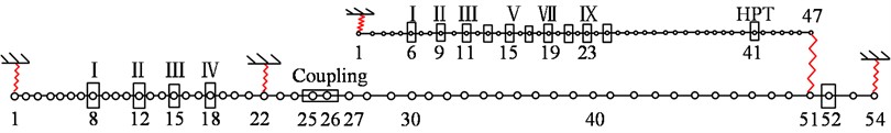
Fig. 11The first three orders natural frequencies and modes for the low-pressure rotor of the prototype
a) The first order (89.6 Hz)
b) The second order (122.3 Hz)
c) The third order (156.8 Hz)
The first three natural frequencies and vibration modes of the low-pressure rotor system of the prototype are obtained as shown in Fig. 11. The first vibration mode of the low-pressure rotor of the prototype is the bending of the low-pressure turbine rotor. The second vibration mode is the pitching of the fan rotor. The third vibration mode is the pitching of the fan rotor and the bending of the low-pressure turbine rotor.
The first three natural frequencies and vibration modes of the high-pressure rotor of the prototype are shown in Fig. 12. The first vibration mode is translational of the high-pressure rotor, the second vibration mode is the pitching of the high-pressure rotor, and the third vibration mode is the bending of the high-pressure rotor.
Fig. 12The first three orders natural frequencies and modes for the high-pressure rotor of the prototype
a) The first order (59.8 Hz)
b) The second order (106.4 Hz)
c) The third order (587.7 Hz)
The first three natural frequencies and vibration modes of the dual-rotor system for the prototype are obtained as shown in Fig. 13. The first vibration mode is the bending of the low-pressure turbine rotor and the translational of the high-pressure rotor. The second vibration mode is the bending of the low-pressure turbine rotor and the pitching of the high-pressure rotor; The third vibration mode is the pitching of the fan rotor, bending of the low-pressure turbine rotor, and translation of the high-pressure rotor.
4.2.3. Comparative analysis of results
The first three natural frequencies and vibration modes obtained from the two finite element models of the dual-rotor system are compared, and the following conclusions are obtained: 1) Among the first three vibration modes of the low-pressure rotor system, the low-pressure turbine rotor are the same, and the fan rotor shows bending and pitching in the simplified and prototype model respectively. The relative errors of the first three natural frequencies are 14 %, 0.2 %, and 3.9 % respectively. 2) The first three modes of the high-pressure rotor system are consistent, and the relative errors of the first three natural frequencies are 1 %, 9 %, and 33 % respectively. 3) Among the first three vibration modes of the dual-rotor system, the vibration modes of the low-pressure turbine rotor and the high-pressure rotor are the same. The fan rotor shows the bending vibration mode in the simplified model and the pitching vibration mode in the prototype model. The relative errors of the first three natural frequencies are 0.3 %, 5.2 %, and 8.6 % respectively.
The first three vibration modes of the dual-rotor system obtained in Section 2 based on the analytical dynamic model consist with the results of the prototype model. It further shows that it is reasonable to consider the fan rotor as rigid and the low-pressure turbine shaft as flexible in the rigid-flexible dynamic model of the dual-rotor system.
Fig. 13The first three orders natural frequencies and modes for the dual-rotor system of the prototype
a) The first order (55.7 Hz)
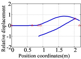
b) The second order (79.7 Hz)
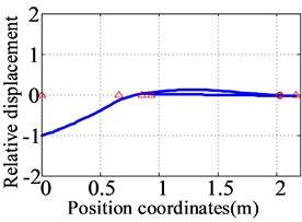
c) The third order (133.5 Hz)
5. Conclusions
In response to the urgent demand for a rotor system model that can reasonably and accurately express the dynamics and vibration characteristics of the rotor system in the study of vibration in aircraft engine rotor systems, this article takes a representative aero-engine dual-rotor system as the research object, established a simplified mechanical model which can reflect the structural characteristics and motion behavior of the prototype model is introduced. Considering the rigid-flexible coupling characteristics of an elastic support with different stiffness and rotor structure, and analytical dynamic model of the dual-rotor system is established. The model contains the kinetic energy of four equivalent discs and the elastic potential energy of five supports and a low-pressure turbine shaft, with 16 degrees of freedom.
The dynamic model of the rigid-flexible coupled dual-rotor system is verified and confirmed by the rigid-flexible coupling multi-body dynamics simulation method and finite element method. The feasibility of using the analytical dynamic model of the dual-rotor system to study the vibration is clarified, which lays a model foundation for the subsequent research on the vibration of the dual-rotor system. It shows that it is reasonable to consider the fan rotor as rigid and the low-pressure turbine shaft as flexible in the rigid-flexible dynamic model of the dual-rotor system.
References
-
Xun Hu, Guihuo Luo, and Deping Gao, “Numerical analysis and experiment of counter-rotating dual-rotor’s steady-state response,” (in Chinese), Journal of Aeronautical Power, Vol. 22, No. 7, pp. 1044–1049, 2007, https://doi.org/10.3969/j.issn.1000-8055.2007.07.004
-
J. Liu, C. Wang, and Z. Luo, “Research nonlinear vibrations of a dual-rotor system with nonlinear restoring forces,” Journal of the Brazilian Society of Mechanical Sciences and Engineering, Vol. 42, No. 9, pp. 1–20, Sep. 2020, https://doi.org/10.1007/s40430-020-02541-w
-
Peng Gao, Lei Hou, and Yushu Chen, “Nonlinear vibration characteristics of a dual-rotor system with inter-shaft bearing,” Shock and Vibration, Vol. 38, No. 15, pp. 1–10, 2019.
-
Guihuo Luo, Hailun Zhou, Fei Wang, and Xiguan Yang, “Dynamic response of co-rotating and counter-rotating dual-rotor system supported on ball bearing,” Journal of Aeronautical Power, Vol. 27, No. 8, pp. 1887–1894, 2012.
-
Guo Chen, “Vibration modeling and analysis for dual-rotor aero-engine,” (in Chinese), Journal of Vibration Engineering, Vol. 24, No. 6, pp. 619–632, 2011.
-
Z. Lu, X. Wang, L. Hou, Y. Chen, and X. Liu, “Nonlinear response analysis for an aero engine dual-rotor system coupled by the inter-shaft bearing,” Archive of Applied Mechanics, Vol. 89, No. 7, pp. 1275–1288, 2019.
-
Xiguan Yang, Guihuo Luo, Zhenyuan Tang, and Fei Wang, “Modeling method and dynamic characteristics of high-dimensional counter-rotating dual rotor system,” Journal of Aeronautical Power, Vol. 29, No. 3, pp. 585–595, 2014.
-
Z.-J. Feng and G.-H. Luo, “Analysis on the dynamic characteristics of the dual-rotor structures of a certain aero-engine,” Vibroengineering Procedia, Vol. 5, pp. 469–474, Sep. 2015.
-
Dayi Zhang, Yehui Liu, Zhichao Liang, Yanhong Ma, and Jie Hong, “Prediction for critical speed of double spools system in aero engines,” Journal of Propulsion Technology, Vol. 36, No. 2, pp. 292–298, 2015.
-
N. Wang, H. Xu, and D. Jiang, “Dynamic model and fault feature research of dual-rotor system with bearing pedestal looseness,” Mathematical Problems in Engineering, Vol. 2016, pp. 1–18, 2016, https://doi.org/10.1155/2016/3817405
About this article

Study on Dynamic Optimization Method of Large Squeeze Film Damper Driven by Data (12072069).
The datasets generated during and/or analyzed during the current study are available from the corresponding author on reasonable request.
Pingping Ma is responsible for providing main ideas and writing articles. Yuehui Dong provides information collection and data analysis. Muge Liu is responsible for revising the format and grammar of the paper. Qingkai Han is responsible for reviewing the content and results.
The authors declare that they have no conflict of interest.
