Abstract
The nonlinear dynamic model of a shared bearing bore-coaxial rotor system was established with nonlinear forces of the rolling bearings and squeeze film dampers considered, Cross coupling frequency was found in cross coupling vibration simulation. Numerical studies were conducted to reveal the mechanism of the coupling vibration for the shared bearing bore-coaxial rotor system. The coupling vibration characteristics and influencing factors of the shared bearing bore-coaxial rotor system were studied. The results show that the coupling vibration is featured by cross-excitation phenomenon and orbit which shows a “circle in circle” pattern. Besides, the angular stiffness of the shared bearing bore has great influences on the coupling vibration. However, the radial stiffness has almost no effect on the coupling vibration.
Highlights
- The nonlinear dynamic model of a shared bearing bore-coaxial rotor system was established.
- Cross coupling frequency was found.
- Reveal the mechanism of the coupling vibration for the shared bearing bore-coaxial rotor system.
- The angular stiffness of the shared bearing bore has great influences on the coupling vibration.
1. Introduction
The shared bearing bore structure has been widely used in high power-to-weight ratio turboshaft engines. It is one of the most important technologies to reduce engine weight, increase power-to-weight ratio and turbine efficiency [1]. The shared bearing bore structure supports both the gas generator and the power turbine rotor, thus to reduce the number of bearing cavity and supports and then the weight of engine [2]. However, vibration of the gas generator would be transmitted to the power turbine rotor and vice versa. And coupling vibration would increase the opportunities of resonance for both rotors [3]. Besides, the power turbine is a typical overhung high-speed flexible rotor system, which is highly sensitive to external excitations, such as the unbalance load and the vibration transmitted by the shared bearing bore. Therefore, it is important to study the coupling dynamics of the shared bearing bore-dual rotor system.
At present, there are very few studies about the shared bearing bore at home and abroad. Most studies of coupling dynamics for dual rotor system with inter-shaft bearing focus on cross excitation phenomena. Gupta et al. [4-5] established the dynamic model of a rolling bearing-dual rotor system by the transfer matrix method. The influences of rolling bearing, moments of inertia and gyroscopic effect were studied and verified. Guskov et al. [6-9] conducted numerical and experimental researches on a dual rotor system to study the coupled unbalance response characteristics. Bonello et al. [10-11] developed a modeling method in frequency domain to study the nonlinear dynamic characteristics of the squeeze film damper (SFD)-dual rotor system. Luo Guihuo et al. [12-13] studied the nonlinear dynamics of the co-and counter-rotating dual rotor system with inter-shaft bearing and SFD. Also, the influences of radial clearance of the inter-shaft bearing were studied. Chen Guo et al. [14-16] established the dynamic model of a casing-rolling bearing-rotor system. The coupling vibration between the rotors were studied. But the influences of the supporting structures were neglected.
The shared bearing bore-coaxial rotor system differs from the rolling bearing-dual rotor system in that the dynamic characteristics of the supporting structure itself have great impact on the rotor’s response. Thus, to promote detailed studies on the dynamic characteristics of the shared bearing bore-coaxial rotor system. the remainder of this paper is organized as follows: the modeling method is presented in Section 2; the influences of radial and the angular stiffness are studied in Section 3; the main conclusions are drawn and discussed in Section 4.
2. Modeling
2.1. The coaxial rotor system
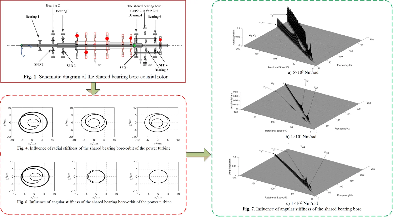
The shared bearing bore coaxial rotor system is shown in Fig. 1. The rotor system consists of the power turbine rotor, the gas generator rotor, the shared bearing bore and squeeze film dampers. The power turbine rotor is supported by bearing 1, 2, 5 and 6. The gas generator is supported by bearing 3 and 4. Bearing 4, 5 and 6 are connected to the outer case by the shared bearing bore. Bearing 1 and 5 adopts the rolling bearing+squirrel cage scheme while the rest supports adopt rolling bearing+squirrel cage+squeeze film damper scheme. Relevant parameters of rotor system are listed in Table 1 to Table 4. In Table 1, and indicate the radial and angular stiffness, respectively. In Table 2, represents the length of the oil film, is radius the oil film, and is the radial clearances. In Table 3, indicates the polar inertia of the disk.
Fig. 1Schematic diagram of the Shared bearing bore-coaxial rotor
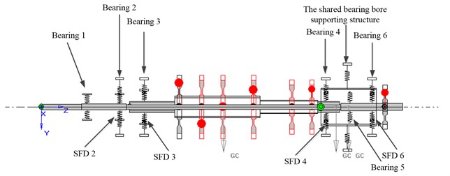
Table 1Stiffness of squirrel cages
Bearing number | / (N/m) | / (N∙m/rad) |
1 | 3.77×10⁶ | 0 |
2 | 2.35×10⁵ | 0 |
3 | 1.13×10⁶ | 0 |
4 | 7.10×10⁵ | 0 |
5 | 4.13×10⁶ | 0 |
6 | 2.30×10⁵ | 0 |
Table 2Parameters of SFD
Support number | / mm | / mm | / mm | Dynamic viscosity / (Pa·s) | |
Power turbine rotor | 2 | 19.0 | 23.0 | 0.05 | 1.0752×10⁻² |
6 | 15.5 | 26.5 | 0.05 | ||
Gas generator rotor | 3 | 9.5 | 25.5 | 0.05 | |
4 | 17.0 | 26.5 | 0.05 |
2.2. Equations of motion
The Timoshenko beam element is adopted to model the shaft and the shared bearing bore. Each beam element consists of 2 nodes with 4 degrees of freedom per node. Translational degrees of freedom in , direction , and rotational degrees of freedom around , axis, respectively, as shown in Fig. 2.
Table 3Parameters of disks
Section number | Starting point / mm | Mass / kg | / (kg·m2) | Unbalance / (g·cm) | Initial phase | |
Gas generator rotor | 1 | 467 | 4.66 | 0.035890 | 2 | 0 |
2 | 543 | 5.26 | 0.044880 | 2 | 0 | |
3 | 615 | 2.01 | 0.008250 | 1 | 0 | |
4 | 718.5 | 0.53 | 0.001110 | 0 | 0 | |
5 | 849 | 2.49 | 0.009724 | 2 | 0 | |
6 | 916.5 | 1.48 | 0.003764 | 2 | 0 | |
Power turbine rotor | 7 | 1164 | 5.16 | 0.072610 | 5 | 0 |
The node displacement vector of the element can be written as:
The equations of motion of the beam element:
where, represents the external force load of the beam element; represents the inertia matrix; and represents the gyroscopic matrix; represents the stiffness matrix; is the rotational speed.
The equations of motion of the disc can be written as:
where – the generalized external force vector, – the inertia matrix, – the gyroscopic matrix.
The expressions for and are shown in Eqs. (4) and (5). Where: indicates the mass of the disc; and indicate the diametral and polar moment inertia of the disc, respectively:
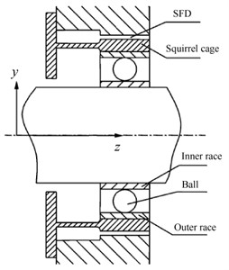
A schematic diagram of the supporting structure is shown in Fig. 4. Thus the supporting force consists of three parts, namely the nonlinear force of the rolling bearing, the nonlinear force of the squeeze film damper and the elastic supporting force . The elastic supporting force is:
where, is the stiffness of the elastic support, and is the displacement of the journal.
Based on the short-bearing assumptions and the Reynolds boundary conditions, nonlinear forces of the squeeze film damper can be expressed as:
where and are the horizontal and vertical displacements of the journal. are Sommerfeld integrals. and are radius and length of the SFD respectively. and denote the dynamic viscosity of the film and the radial clearance of the SFD.; ; ; .
Fig. 2Schematic diagram of beam element
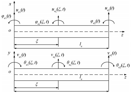
Fig. 3Schematic diagram of the support
As for the rolling ball bearing, based on pure rolling assumption and the Hertz contact theory, nonlinear force of the rolling ball bearing is:
The equations of motion of the beam element and discs are assembled to obtain the equation of motion of the rotor system:
where, , , represent the inertia, gyroscopic and stiffness matrix of the system, respectively. is the generalized external force vector of the system, including unbalance force, nonlinear forces of the rolling bearing and the squeeze film dampers.
Mathematically, the model is a set of nonlinear second order differential equations. The computational efficiency of which depends on the numerical methods applied and the total DOFs of the rotor system. To combine accuracy of the finite element model and computational efficiency, the fixed interface modal synthesis is applied to reduce dimension of the mathematical model and thus the computational effort. Detailed procedures can be seen in reference [12-13], which will not be repeated here.
3. Results and discussion
3.1. Influence of the radial stiffness of the shared bearing bore structure
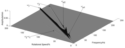
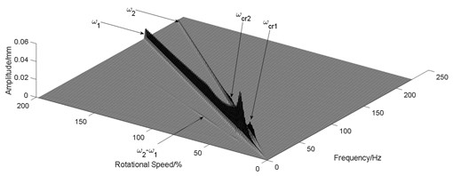
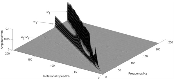
To investigate the influence of the shared bearing bore structure on the coupled vibration response, the radial stiffness of the shared bearing bore structure was taken at 1×10⁶ N/m, 1×10⁸ N/m and 1×10¹⁰ N/m respectively while other parameters remain unchanged. The orbit is shown in Fig. 4 and the waterfall diagram of the response of the power turbine disc is shown in Fig. 5.
It can be seen from Fig. 4 that the orbit of the turbine shows a pattern of circle in circle due to the “cross excitation”. Also, the orbit plot in Fig. 4 indicates that increasing the stiffness of the shared bearing bore structure would lead to decrease of the amplitude of the power turbine disc.
Fig. 4Influence of radial stiffness of the shared bearing bore-orbit of the power turbine

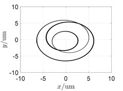
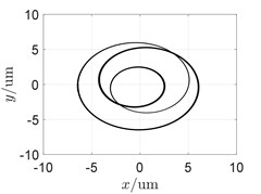
Fig. 5Schematic diagram of the support
a) 1×10⁶ N/m
b) 1×10⁸ N/m
c) 1×10¹⁰ N/m
3.2. Influence of the angular stiffness of the shared bearing bore structure
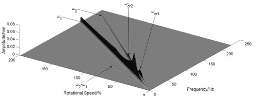
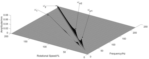
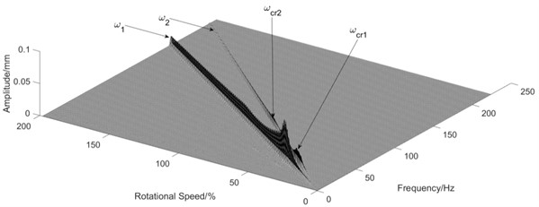
Similar to Section 3.1, different values of the angular stiffness of the shared bearing bore structure were taken with the other parameters remain unchanged. The orbit of the turbine disc at 5400 r/min is shown in Fig. 6 and the waterfall diagram is shown in Fig. 7.
Fig. 6Influence of angular stiffness of the shared bearing bore-orbit of the power turbine
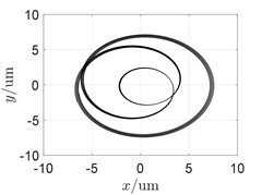
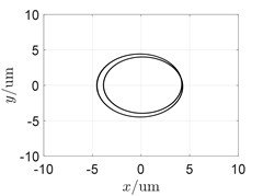
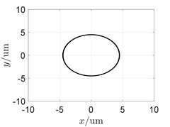
Fig. 7Influence of angular stiffness of the shared bearing bore
a) 5×10³ Nm/rad
b) 1×10⁴ Nm/rad
c) 1×10⁶ Nm/rad
It can be seen from Fig. 7 that the “cross excitation” phenomenon was gradually weakened with increasing angular stiffness of the shared bearing bore. This was also indicated by the orbit plot shown in Fig. 6. The orbit of the power turbine disc at 5400 r/min gradually forms only one circle, Fig. 6(c), instead of multiple circles, Fig. 6(a). Thus, the angular stiffness of the shared bearing bore structure can effectively reduce the cross-excitation phenomenon as well as the vibration transmission between both rotors.
4. Conclusions
The dynamic characteristics of a coaxial-rotor system with the shared bearing bore structure was studied. The influences of the radial and angular stiffness of the shared bearing bore were simulated and analyzed. The main conclusions are as follows:
(1) The cross excitation phenomenon was observed in coaxial rotor system with shared bearing bore structure for the first time, indicating that the shared bearing bore structure plays a similar role like the inter-shaft bearing in commercial turbofan aeroengine. The vibration of one rotor would be transmitted to another one by the shared bearing bore thus to increase the opportunity of resonance of the rotor system.
(2) By numerical simulation it was found that both the radial and angular stiffness of the shared bearing bore has influences on the dynamic response of the rotor system. However, increasing the radial stiffness has little effect on weakening the cross excitation phenomenon. In contrast, increasing the angular stiffness would greatly reduce the cross excitation frequency component, thus the vibration amplitude.
References
-
Keshava B. Kumar, Nagendra Somanath, and William A. Sowa, “Sowa W A. Mid-Turbine Frame,” U.S. Patent US8181466, 2021.
-
Hu Xiao Yu, Small and Medium Aircraft Engines. Beijing, China: Aviation Industrial Publishing House, 2006.
-
J. Zhang et al., “Coupling vibration characteristics analysis of shared support-rotors system,” (in Chinese), Journal of Beijing University of Aeronautics and Astronautics, Vol. 45, No. 9, pp. 1902–1910, 2019, https://doi.org/10.13700/j.bh.1001-5965.2019.0002
-
K. Gupta and K. D. Gupta, “Unbalance response of a dual rotor system: theory and experiment,” Journal of Vibration and Acoustics, Vol. 115, No. 4, pp. 427–435, 1993, https://doi.org/10.1115/1.29303
-
K. Gupta et al., “Effect of rotary inertia and gyroscopic moments on dynamics of two spool aero engine rotor,” in International Gas Turbine and Aeroengine Congress and Exposition, pp. 1–14, 1993.
-
K. Gupta, R. Kumar, M. Tiwari, and O. Prakash, “Effect of rotary inertia and gyroscopic moments on dynamics of two spool aeroengine rotor,” ASME 1993 International Gas Turbine and Aeroengine Congress and Exposition, Vol. 2007, No. 2, pp. 308–321, May 1993, https://doi.org/10.1115/93-gt-045
-
C. Gibert, M. Guskov, L. Sanchez, and F. Thouverez, “Damping coefficient estimation of a squeeze-film damper operating in a dual shaft test rig,” Mécanique and Industries, Vol. 11, No. 5, pp. 297–308, Sep. 2010, https://doi.org/10.1051/meca/2010067
-
M. Guskov, J.-J. Sinou, and F. Thouverez, “Multi-dimensional harmonic balance applied to rotor dynamics,” Mechanics Research Communications, Vol. 35, No. 8, pp. 537–545, Dec. 2008, https://doi.org/10.1016/j.mechrescom.2008.05.002
-
M. Guskov and F. Thouverez, “Harmonic balance-based approach for quasi-periodic motions and stability analysis,” Journal of Vibration and Acoustics, Vol. 134, No. 3, pp. 432–443, Jun. 2012, https://doi.org/10.1115/1.4005823
-
P. Bonello and P. M. Hai, “Computational studies of the unbalance response of a whole aero-engine model with squeeze-film bearings,” Journal of Engineering for Gas Turbines and Power, Vol. 132, No. 3, pp. 411–420, Mar. 2010, https://doi.org/10.1115/1.3159381
-
P. M. Hai and P. Bonello, “A computational parametric analysis of the vibration of a three-spool aero-engine under multi-frequency unbalance excitation,” ASME Turbo Expo 2010: Power for Land, Sea, and Air, Vol. 133, No. 7, pp. 235–248, Oct. 2010, https://doi.org/10.1115/gt2010-22801
-
X.-G. Yang, G.-H. Luo, W.-D. Wen, and Et. Al, “Impacts of support’s nonlinear characteristics on response characteristics of dual rotor system,” (in Chinese), Journal of Vibration Engineering, Vol. 27, No. 4, pp. 572–582, 2014, https://doi.org/10.3969/j.issn.1004-4523.2014.04.013
-
G.-H. Luo, X.-G. Yang, and F. Wang, “Research for response characteristics of rub-impact high-dimensional dual-rotor system,” (in Chinese), Journal of Vibration Engineering, Vol. 32, No. 9, pp. 100–107, 2015, https://doi.org/10.16385/j.cnki.issn.1004-4523.2015.01.013
-
G. Chen, “Whole aero-engine vibration coupling dynamics model including modeling of complex ball and roller bearings,” (in Chinese), Journal of Aerospace Power, Vol. 32, No. 9, pp. 2193–2204, 2017, https://doi.org/10.13224/j.cnki.jasp.2017.09.019
-
G. Chen, “Rotor-ball bearing-stator coupling dynamic model including rubbing coupling faults,” (in Chinese), Journal of Vibration Engineering, Vol. 20, No. 4, pp. 361–368, 2007, https://doi.org/10.3969/j.issn.1004-4523.2007.04.008
-
Y. Wu, Y. Zhang, and G. Chen, “Dynamic modeling and analysis of aeroengine with supporting non – concentricity,” (in Chinese), Aeroengine, Vol. 44, No. 5, pp. 1–8, 2018, https://doi.org/10.13477/j.cnki.aeroengine.2018.05.001
About this article

The authors have not disclosed any funding.
The datasets generated during and/or analyzed during the current study are available from the corresponding author on reasonable request.
The authors declare that they have no conflict of interest.
