Abstract
The traditional dynamic analysis of the finite element structure is mostly focused on the mode analysis. In the paper, the finite element method is combined with the power flow analysis to analyze and optimize the vibration transmission characteristics of the shared bearing bore, so that the vibration energy transmitted to the mounting flange is minimized. The analysis shows that the elastic ring and the outer case play an important role in vibration transmission and reduction. An optimization model is established to improve the vibration reduction rate of the shared bearing bore. The results show that the optimization can effectively improve the vibration reduction rate of the shared bearing bore, approximately 15 % reduction of peak response is achieved.
Highlights
- The finite element method is combined with the power flow analysis.
- Optimize the vibration transmission characteristics of the shared bearing bore.
- An optimization model is established and 15% reduction of peak response is achieved.
1. Introduction
The shared bearing bore structure is widely applied in modern turboshaft engines, such as EJ200 and MTR390. It is becoming lighter and thin-walled plates or shell structures are widely used to pursue higher power-to-weight ratio for the turboshaft engines. Consequently, phenomenon such as closely spaced modes and geometric nonlinearity gradually shows up [1]. At the same time, the shared bearing bore structure is subject to various vibration loads (e.g. unbalance load from the rotor, meshing excitation from the transmission gear, etc.). With inappropriate design, the structure itself as well as the accessory system mounted on it are prone to deformation, cracks and even fatigue damage under these multi-frequency excitations. Also, the vibration of the sharing bearing bore can be transmitted to the rotor system by bearings, which might deteriorate the operating conditions of the rotor system. Therefore, the dynamic characteristics of the shared bearing bore structure must be carefully designed to reduce the vibration transmission between the rotor and stator and thus the vibration level of the aero engine.
Traditionally, the most effective measure to isolate and reduce vibration is to insert the inertia, elastic and damping components between the rotor and stator. The vibration energy can be transferred to specified component and dissipated [2]. Either the force or the motion can be isolated and reduced [3]. Based on damping mass, Wang Zuhua et al. [4] optimized the vibration isolating structure of the ship bulkheads. Kuang Chengyu et al. [5] designed the isolation floating raft for a ship. The basic principle is to suppress the elastic waves by cyclic structures. Also, the vibration isolating characteristics were studied. By experimental study, Jiang Hongyuan et al. [6] verified that more excellent isolating characteristics can be achieved with the proposed metallic rubber. However, it is difficult to achieve the ideal vibration reducing level with the usual method for the shared bearing bore structure due to the combination of plate and shell. Thus, the active or semi-active intervention based on time-delay feedback [7] has been introduced in recent years. It can be briefly described as introducing an energy source from the outside to cancel the vibration and reducing the vibration level of the system [8-9]. Nagai et al. [10] studied the active control measures of a train suspension system with the neural network. A two-dimension fuzzy active vibration isolation system based on a magnetostrictive actuator is designed by Mei Deqing et al. [11] for a micro-manufacturing platform system. However, the active vibration isolator has been restricted by the limited output force, response time and signal hysteresis [12-13]. Also, additional mass must be added, which would reduce the reliability and increasing the weight of the aero engine. Ma Yanhong et al. [14] proposed that the vibration can be isolated and reduced by increasing the stiffness/mass distribution difference between adjacent components of the shared bearing bore structure. But further theoretical analysis and experimental validation are still lacking.
In this paper, the finite element method and the vibration power flow analysis were combined to analyze the vibration transmission characteristics of the shared bearing bore structure. Then the structure is optimized to reduce and isolate the vibration based on the genetic algorithm.
2. Modeling
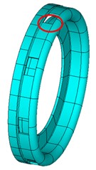
The shared bearing bore of a certain turboshaft engine is illustrated in Fig. 1. The structure consists of two squirrel cages, elastic ring, supporting plate, inner case and outer case. The 4# bearing is located in the front squirrel cage to support the gas generator rotor while the 5# and 6# bearings are located in the aft squirrel cage to support the power turbine rotor. Material properties for squirrel cages are: density 8220 kg/m3, Young’s modulus 186 GPa, Poisson’s ratio 0.28. Material properties for other components are: density 8000 kg/m3, Young’s modulus 172 GPa, Poisson’s ratio 0.27. The finite element model of the shared bearing bore is shown in Fig. 2. The fem model consists of 113685 nodes and 99606 elements.
Fig. 1A schematic diagram of the shared bearing bore
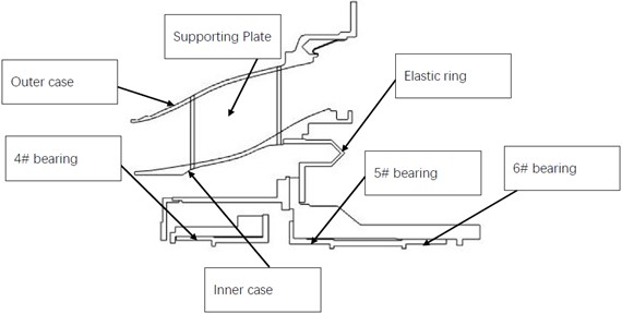
Fig. 2Finite element model of the shared bearing bore
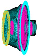
a) Boundary condition
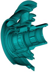
b) Cutaway view of the mesh
To obtain the power flow distribution of the model illustrated in Fig. 2, the power flow theory must be modified. The steady-state power flow of a point in the structure can be described as [15]:
where – the force; – the velocity.
For periodic harmonic vibration, the power flow in one period can be written as:
The harmonic excitation force and the corresponding response can be rewritten as:
where – the amplitude of the excitation force, – the circular frequency of the harmonic vibration. Steady response of the structure under harmonic excitation is: – amplitude of the displacement, – the lagging phase angle.
Differentiating Eq. (4) with time to obtain the velocity:
Substituting Eq. (5) and Eq. (3) into Eq. (2) to obtain:
In complex form, . In which: – Fourier transformed ; – Fourier transformed ; represents conjugate; – real part of a complex number.
To combine the finite element method and the power flow method, a regular hexahedron element of a three-dimensional solid is illustrated in Fig. 3. The normal stress components are , and . The shear stress components are , , .
Fig. 3Element of a three-dimensional solid
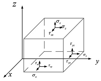
Thus, the unit power flow through each surface is:
In Eq. (7), is the normal stress in direction, and are the shear stress in direction 1 and 2. , and represent the conjugate of complex velocities in direction , 1 and 2. For steady-state vibration, it holds that . In which is the complex displacement in direction . For three dimensional elements in finite element method, each node has 3 degree of freedoms, , and . The power flow in each dof can be obtained by substituting into Eq. (7):
where , and are the power flow in , and direction. and are the conjugate of the complex displacement in , and direction.
3. Results and discussion
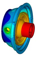
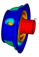
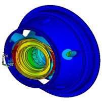
With the FEM model illustrated in Fig. 2, modal and harmonic analysis were conducted to provide basis for subsequent power flow analysis and optimization. The first fourth natural frequencies and corresponding mode shapes of the shared bearing bore structure are listed in Table 1 and Fig. 4. From Fig. 4 it can be seen that the outer case is prone to vibrate for the 1st mode while the elastic ring and squirrel cages would tilt under 2nd to 4th natural frequency. However, the operating range for the power turbine and the gas generator are 0-20000 rpm and 0-40000 rpm respectively. Thus, only the first mode might be excited during operation.
Table 1The first fourth natural frequencies
Natural Frequency/Hz | |
1 | 588.2 |
2 | 633.5 |
3 | 758.4 |
4 | 876.7 |
Fig. 4Mode shapes of the first fourth mode
a) 1st
b) 2nd
c) 3rd
d) 4th
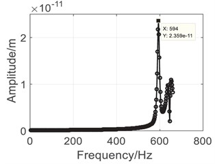
Results of the harmonic analysis are listed in Fig. 5. Comparing with the modal analysis results, it can be seen that the gas generator (0-40000 rpm) is the main source of vibration for the shared bearing bore structure. The outer case as well as the bearings would reach peak response at the 1st natural frequency, which is approximately 590 Hz. Then the power flow analysis was conducted to analyze the vibration transmission characteristics.
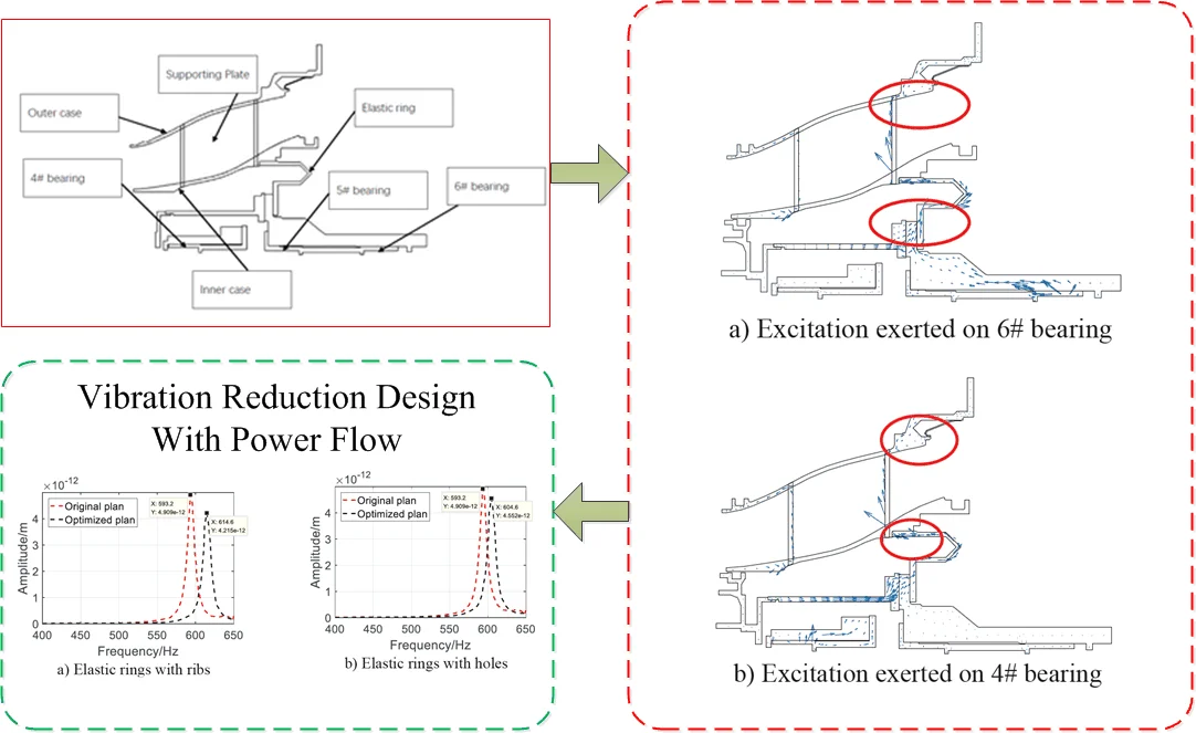
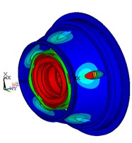
Vector plot of the power flow with different excitation sources are illustrated in Fig. 6. Both Fig. 6(a) and Fig. 6(b) indicated that the energy of the vibration introduced by the rotor was transmitted to the inner and outer case by the elastic ring. Thus, the elastic ring is the key component to reduce and isolate vibration. Also, as pointed out by the red circles in Fig. 6, power flow back-flow phenomena were observed in the elastic ring and the outer case, which indicates that these two components play an important role in vibration energy dissipation. Consequently, the following optimization would focus on these two components.
Fig. 5Harmonic analysis results
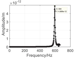
a) Outer case
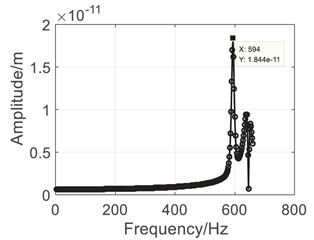
b) 4# Bearing
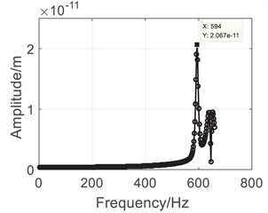
c) 5# Bearing
d) 6# Bearing
Fig. 6Vector plot of power flow
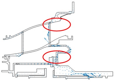
a) Excitation exerted on 6# bearing
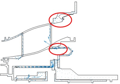
b) Excitation exerted on 4# bearing
4. Optimization
Analysis in previous section reviewed that the elastic ring plays an important role in vibration transmission and dissipation. Therefore, the optimization problems were formulated under two different conditions. For the first case, only the elastic ring was modified. Ribs were added to the elastic ring, Fig. 7(a). Dimensionless circumferential width of the ribs was chosen as the design variables. Then circumferential holes were made on the elastic ring, Fig. 7(b). Dimensionless circumferential width of the holes was chosen as the design variables. The objective function and constraints were listed in Eq. (9):
where and represents the dimensionless circumferential width of the ribs and holes. is the power flow through the flange of the outer case. In this paper, the genetic algorithm with adaptive global search is used as the optimization method.
Results of the optimization are illustrated in Fig. 8. After optimization, 0.498 ≈ 0.50 and 0.310 ≈ 0.30. The vibration amplitude of the flange for the original plan and the optimized plan are compared in Fig. 8(a) and Fig. 8(b). The peak response was reduced approximately 15 % and 7 % for the rib plan and the hole plan respectively. The power flow was 57 W for the original plan, 41 W for the rib plan and 49 W for the hole plan, indicating that increasing the stiffness of the elastic ring would reduce the vibration transmission. Also, the upper limit of is 1.0, the optimized result is 0.50, which means further increasing of the stiffness has little effect in vibration reduction.
Fig. 7Optimization plans
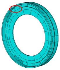
a) Elastic rings with ribs
b) Elastic rings with holes
Fig. 8Optimization results
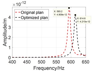
a) Elastic rings with ribs
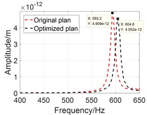
b) Elastic rings with holes
5. Conclusions
The power flow method is combined with the finite element method to analyze the vibration transmission characteristic of the shared bearing bore. The analysis shows that the elastic ring and the outer case play an important role in vibration transmission and reduction. Power flow back-flow phenomena was observed in these two components. An optimization model is established to improve the vibration reduction rate of the shared bearing bore by optimizing the circumferential width of the rib and the hole of the elastic ring. The results show that the optimization can effectively improve the vibration reduction rate of the shared bearing bore, approximately 15 % reduction of peak response is achieved.
References
-
D. Z. Wen, “Several dynamic characteristics of aero-engine case model,” Harbin Institute of Technology, Harbin, China, 2015.
-
Z. Q. Lu and L. Q. Chen, “Some recent progresses in nonlinear passive isolations of vibration,” (in Chinese), Journal of Theoretical and Applied Mechanics, Vol. 49, No. 3, pp. 550–564, 2017, https://doi.org/10.6052/0459-1879-17-064
-
C. Crede, Vibration and Shock Isolation. New York, USA: John Wiley and Sons, 1951.
-
Z. H. Wang, H. B. Zhou, and F. Ji, “Vibration isolation design of typical hull bulkhead structures,” (in Chinese), Ship and Boat, Vol. 22, No. 3, pp. 26–33, 2011, https://doi.org/10.3969/j.issn.1001-9855.2011.01.005
-
C. Y. Kuang, “Design and vibration isolation characteristics research of a floating raft constructed with periodic structures,” Shanghai Jiao Tong University, Shanghai, China, 2011.
-
H. Y. Jiang et al., “Research on dynamic and static characteristics of metal rubber isolator used in aero engine,” (in Chinese), Acta Aeronautica et Astronautica Sinica, Vol. 25, No. 2, pp. 140–142, 2004, https://doi.org/10.3321/j.issn:1000-6893.2004.02.011
-
J. Xu, “Advances of research on vibration control,” (in Chinese), Chinese Quarterly of Mechanics, Vol. 36, No. 4, pp. 547–565, 2015, https://doi.org/10.15959/j.cnki.0254-0053.2015.04.001
-
Zhang Chun-Hong, “The retrospection and prospection of active vibration isolation technique,” (in Chinese), Journal of Hohai University Changzhou, Vol. 16, No. 2, pp. 1–5, 2002.
-
L. Zhang et al., “Active vibration isolation and its application and development,” (in Chinese), Machine Tool and Hydraulics, Vol. 2005, No. 2, pp. 5–8, 2005, https://doi.org/10.3969/j.issn.1001-3881.2005.02.002
-
M. Nagai, A. Moran, Y. Tamura, and S. Koizumi, “Identification and control of nonlinear active pneumatic suspension for railway vehicles, using neural networks,” Control Engineering Practice, Vol. 5, No. 8, pp. 1137–1144, Aug. 1997, https://doi.org/10.1016/s0967-0661(97)00107-x
-
D. Q. Mei and Z. C. Chen, “Research on precision isolation system of micro manufacturing platform,” (in Chinese), Optics and Precision Engineering, Vol. 9, No. 6, pp. 506–510, 2001, https://doi.org/10.3321/j.issn:1004-924x.2001.06.003
-
C. C. Fuller, S. Elliott, and P. A. Nelson, Active Control of Vibration. New York, USA: Academic Press, 1996.
-
W. K. Gawronski, Advanced Structural Dynamics and Active Control of Structures. New York, USA: Springer, 2004.
-
Y. H. Ma et al., “Key design technology of mid turbine frame for turboshaft engine,” (in Chinese), Aeroengine, Vol. 40, No. 4, 2014, https://doi.org/10.13477/j.cnki.aeroengine.2014.04.007
-
X. Wu, S. Zhu, and G. Cheng, “Isolation system optimization by ANSYS for minimizing vibration power flow,” (in Chinese), Journal of Wuhan University of Technology, Vol. 29, No. 2, pp. 186–189, 2005, https://doi.org/10.3963/j.issn.2095-3844.2005.02.007
About this article

The authors have not disclosed any funding.
The datasets generated during and/or analyzed during the current study are available from the corresponding author on reasonable request.
The authors declare that they have no conflict of interest.
