Abstract
Rotor systems with coupling consist of two rotors, rolling bearings, sealing components, and nonlinear coupling. Currently, rotor systems with coupling are widely used in marine engines, aerospace engines, and various vehicle engines. In studies of rotor systems with coupling, the coupling connecting both sides of the rotor are often regarded as a linear stiffness unit. But in actual engineering, the torsional stiffness of the coupling varies with the speed of the system, and the variation of the coupling stiffness will affect the dynamic characteristics of the rotor. Based on the above phenomena, this study establishes the rotor model of driveshaft-Geislinger coupling-driveshaft in diesel engines and obtains the modal, frequency, and transient response analysis results of the rotor system with nonlinear Geislinger coupling. The modal, frequency, and transient response analysis results of the nonlinear model are compared with those of the linear model. This study can provide theoretical support for the vibration analysis of nonlinear rotor systems with connected Geislinger coupling.
Highlights
- A kind of nonlinear driveshaft-Geislinger coupling-driveshaft model for diesel engines and its geometric parameters are proposed. Deriving the torsional vibration equations for the driveshaft-Geislinger coupling-driveshaft model.
- Constructing the linear system that differs only in the coupling stiffness. Calculating the modal and frequency response of the nonlinear driveshaft-Geislinger coupling-driveshaft model and comparing the frequency response result of the nonlinear model frequency response with the linear model result.
- Providing two different rotor system working conditions. Calculating the transient response of the nonlinear driveshaft-Geislinger coupling- driveshaft model and the linear model at static, 220 Hz, and 300 Hz rotating speeds. Comparison of the trends and peaks in the transient response curves of the nonlinear and linear models at static, 220 Hz, and 300 Hz rotating speeds.
- The article concludes the following, the linear model has an error in natural frequency values of the frequency response as the system speed varies. And the natural frequency values of the nonlinear model are generally higher than the linear model. The transient response torsional angle amplitude and curve trend of the model change at static, 220 Hz, and 300 Hz rotating speeds due to the connected stiffness.
1. Introduction
Rotor systems are widely used in vehicles [1, 2], aero-engines [3, 4] and marine engineering [5, 6], where rotor systems with couplings are more common, usually with two rotors on each side, connected by couplings. The coupling reduces the span of the rotor and transmits the torque of both rotors, which plays a key role in the engine. The main relevant studies on the torsional dynamics of rotor systems are: the turbo generator rotor system was accurately predicted by static and dynamic frequency drift simulation analysis [7]. In [8], the authors investigated the harmonic twisting torques dynamic analysis for the torsional vibration of shafts. In [6], the paper calculated the natural torsional vibration mode of marine power transmission systems by two methods. In [9], the torsional vibration of the single rotor-system model was researched, and three markers were placed on the locations of the left and right shaft bearings. In [10], presenting the frequency and active power control method for the wind turbine and diesel engine systems. In these works on the rotor system dynamics, modal, frequency response, and transient response analytical methods are used, and the coupling connecting the two rotors is treated as a linearly constant stiffness. However, the coupling stiffness of a rotor system with connected coupling is nonlinear and varies with the speed of the system [2, 11]. Changing the coupling stiffness will affect the dynamic performance of the connected rotor on both sides, which may cause nonlinear dynamic behaviors such as jump, bi-stable, and combination resonance [12]. Therefore, it is necessary to analyze the dynamics of a rotor system with nonlinear coupling.
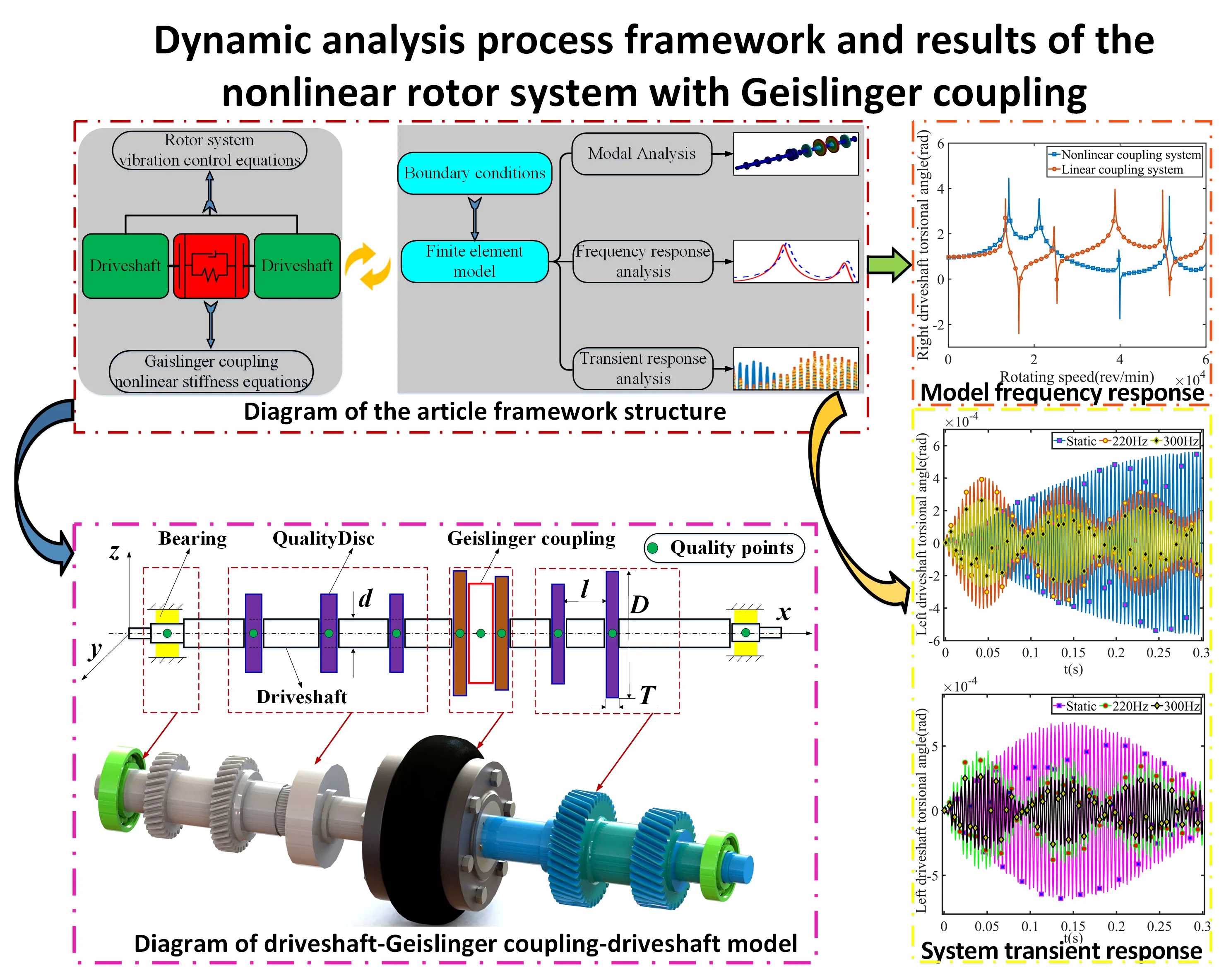
In this study, Section 2 establishes the driveshaft-Geislinger coupling-driveshaft model and provides physical parameters. Section 3 develops the nonlinear coupling stiffness and the torsional vibration equations for the model. In Section 4, the modal, frequency, and transient response analysis results of the model are obtained to compare the differences between the nonlinear and linear results. The effect of the nonlinear stiffness on the transient response is also investigated. Finally, conclusions are given in Section 5. The framework structure of this study is shown in Fig. 1.
Fig. 1Diagram of the article framework structure
2. Driveshaft-Geislinger coupling-driveshaft model
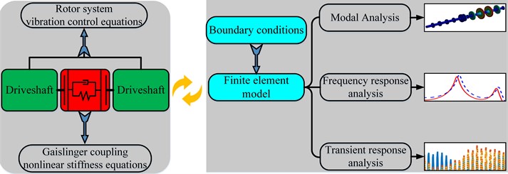
In diesel engines, the commonly used rotor system can be divided into two different driveshaft parts and the Geislinger coupling part, the model is shown in Fig. 2.
Fig. 2Diagram of driveshaft-Geislinger coupling-driveshaft model
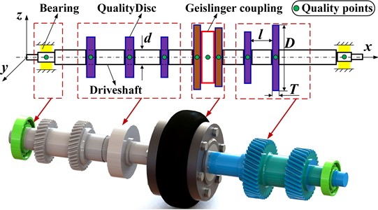
Fig. 2 shows the driveshaft-Geislinger coupling- driveshaft model in the Cartesian coordinate , with the center of the left end of the crankshaft at the origin . The red frame represents the nonlinear Geislinger coupling, with two driveshafts mounted on both sides. The purple frames represent the quality discs of driveshaft. The yellow frames represent the rolling bearings on the end of the driveshaft. The physical material of the driveshaft-Geislinger coupling-driveshaft model is shown in Table 1.
Table 1Material parameters of the driveshaft-Geislinger coupling-driveshaft system
Parts | Material | Density () kg/m3 | Young’s modulus () 1011 MPa | Poisson’s ratio () |
Coupling body | 42CrMo | 7800 | 2.06 | 0.3 |
Coupling Spring plate | 50CrVA | 7870 | 2.09 | 0.3 |
Left driveshaft | S275N | 7850 | 2.11 | 0.3046 |
Right driveshaft | 45# | 7850 | 2.06 | 0.3 |
In the analysis, the simplification of nodal torsional stiffness and rotational inertia is necessary, and the equations of torsional stiffness and rotational inertia are as follows [13]:
Using Eq. (1), the torsional stiffness and rotational inertia of the system are shown in Table 2.
Table 2Geometric parameters of the driveshaft-Geislinger coupling-driveshaft system
Numbering | Inertia 10-3kg·m2 | Rotational stiffness 106 N·m/rad | Length mm | Diameter mm |
Driveshaft (1) | 20.81 | 2.94 | 270 | 100 |
Quality disc (2) | 76.71 | 878.01 | 30 | 240 |
Driveshaft (3) | 20.03 | 3.05 | 260 | 100 |
Quality disc (4) | 76.71 | 878.01 | 30 | 240 |
Driveshaft (5) | 20.03 | 3.05 | 260 | 100 |
Quality disc (6) | 64.70 | 740.57 | 30 | 230 |
Driveshaft (7) | 24.82 | 5.28 | 220 | 110 |
Geislinger coupling (8) | 40.73 | Nonlinear | – | – |
Driveshaft (9) | 16.18 | 3.70 | 210 | 100 |
Quality disc (10) | 18.22 | 4612.32 | 20 | 330 |
Driveshaft (11) | 11.12 | 2.32 | 220 | 90 |
Quality disc (12) | 23.13 | 5836.27 | 20 | 350 |
Driveshaft (13) | 12.64 | 2.04 | 250 | 90 |
3. Nonlinear stiffness and system vibration equations
To build the system vibration equation, the Geislinger nonlinear stiffness should be determined:
where represents system vibration frequency. represents the static stiffness of couplings. represents coupling natural frequency [2]. In the oil-filled Geislinger couplings, the damping factor and dynamic damping equation can be expressed as:
where represents Geislinger damping. represents the damping factor. represents coupling natural frequency.
In this study, the Geislinger coupling type is B41/5/45HC, the coupling static stiffness is 0.329×10⁶ Nm/rad, coupling natural frequency is 610 rad/s [14].
For a torsional rotor system with connected coupling, the vibration equation is:
where , , , , and represent the rotational inertia, nodal damping, torsional stiffness, torsional torque, and torsional angle matrixes respectively.
Taking the components of the nonlinear system into Eq. (4), the equation can be written in:
where subscript represents different components of the system, such as represents Geislinger coupling, represents the driveshaft on the right side, and represents driveshaft on the left side.
In a rotor system, the magnitude and type of torsional torque to each node subjected differs as the two drive shafts of the system are in different working conditions. This study focuses on harmonic and constant torsional torque, which can be expressed as:
where and 0, 0, represents the constant torsional torque. When , and 0, represents the harmonic torsional torque. When , and 0, the node is without torque.
In Eqs. (4) and (5), the rotational inertia, nodal damping, and torsional stiffness matrices of the above system are distributed as:
where the rotational inertia is distributed by two energy-distributed inertia matrices. When 8, the system torsional stiffness and damping are nonlinear. Taking Eqs. (2), (3), (6) and (7) into Eq. (5) can get a detailed vibration equation for each node of the system.
4. Finite element analysis of the nonlinear model
The finite element model and coordinate in this section use the simplified equivalent model in Fig. 2. According to the material and physical parameters of Table 1 and Table 2, the finite element modal of the driveshaft-Geislinger coupling-driveshaft is established. Modal meshing uses the Cartesian grid, the partition interval size is 0.026 m. The bearing at both ends of the driveshaft is modeled with COMBI214 units, providing the bearing support force in and directions. The Geislinger coupling connecting the two drive shafts is simplified with the Torsional Spring function, which inputs the torsional stiffness and torsional damping.
The boundary condition of the driveshaft-Geislinger coupling-driveshaft system is used the Cylindrical Support function, which allows it to only rotate in the direction, and the remaining five degrees of freedom are restricted. Through the finite element model of the system, the 1st to 8th order natural frequency and modal shapes of the system are calculated, as shown in Table 3.
In Table 3, the 1st and 2nd order modals are integral modal shapes, where the torsional vibration occurs in all mass discs and shaft segments. In the 2nd to 7th order modals, the torsional vibration occurs in the mass discs and shaft segments of the unilateral driveshaft, which is the partial modal shapes. The frequency responses of the nonlinear system and linear system are shown in Fig. 3, and the linear system only differs the connection stiffness, which is 0.25×10⁶ Nm/rad.
Frequency response analysis of the system speed at 0-2000 Hz (0-12×104 rpm), which includes the 1st to 7th order modal shapes. In order to research the transmission effect of the system torsional angle, the sampling point is placed on the first mass disc of the right driveshaft.
Table 3Natural frequencies and Modal shapes of the driveshaft-Geislinger coupling-driveshaft system
Order | Natural frequency (Hz) | Modal shapes | Modal features |
1 | 220.64 | 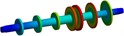 | Torsional mode of both sides driveshaft |
2 | 302.5 | 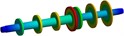 | Torsional mode of both sides driveshaft |
3 | 625.31 | 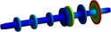 | Torsional mode of the right-side partial mass disc |
4 | 816.06 | 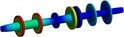 | Torsional mode of the left-side partial mass disc |
5 | 991.92 | 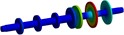 | Torsional mode of the right-side mass disc |
6 | 1403.1 | 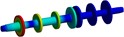 | Torsional mode of the left-side mass disc |
7 | 1809.7 | 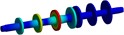 | Torsional mode of the left-side mass disc |
8 | 5254.8 | 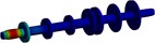 | Torsional mode of the left-side partial shaft |
Obviously, the connection stiffness of the nonlinear system increases as the system speed increases, resulting in a change in peak frequencies. In 3rd to 7th order modal shapes, the peak frequencies of nonlinear system (39718 rpm, 51477 rpm, 60360 rpm, 87417 rpm, and 110818 rpm) are higher than linear system (38818 rpm, 49917 rpm, 60960 rpm, 84358 rpm, and 108720 rpm). Such errors in frequency response due to inaccurate connection stiffness are not conducive to understanding the overall vibration characteristics of the system.
To investigate the effect of nonlinear stiffness on transient response, the transient responses of the system are compared at static, 220 Hz, and 300 Hz rotating speeds. The torsion angle is checked on the mass discs on each side of the system, as shown in Fig. 4.
In the system, the right-side driveshaft has a smaller torsional angle than the left-side driveshaft because the right-side driveshaft needs the connected stiffness for the modal shape transmission. The response peaks of 7.29×10⁻⁴, 5.34×10⁻⁴, and 2.74×10⁻⁴ rad on the left-side driveshaft are higher than 5.51×10⁻⁴, 3.96×10⁻⁴, and 2.65×10⁻⁴ rad on the right-side. In static state, the connected stiffness is low and the response of the whole system is poorly attenuated. The response amplitude is on the rise in the first 0.3s with no obvious decrease. As the coupling stiffness increases, the torsional transfer effect on both sides is enhanced and the system amplitude fluctuates significantly.
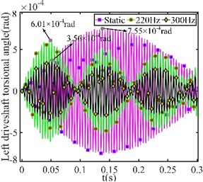
Due to the larger amplitude of the right-side excitation torque, the right-side driveshaft has a larger torsional angle in Fig. 5. The simultaneous application of harmonic torque to both sides driveshaft results the transient response at static showing a significant decrease compared to Fig. 4. In general, the respond trend in the second working condition is consistent with Fig. 4.
Fig. 3Comparison of the linear and nonlinear model frequency response
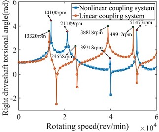
a) Frequency response from 0-6×10⁴rpm
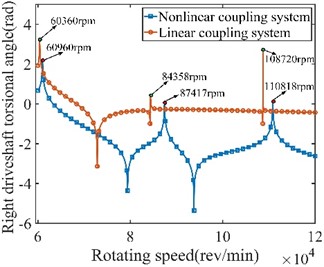
b) Frequency response from 6×10⁴-12×104 rpm
Fig. 4System transient response under left-side excitation torque
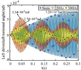
a) Left-side sampling point torsional angle
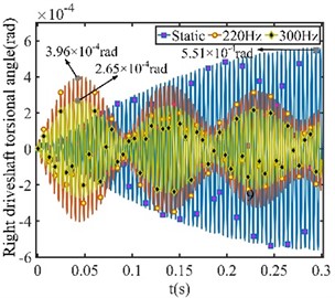
b) Right-side sampling point torsional angle
Fig. 5System transient response under both sides of excitation torque

a) Left-side sampling point torsional angle
b) Right-side sampling point torsional angle
5. Conclusions
In this study, the torsional vibration equations and finite element analysis of the driveshaft-Geislinger coupling-driveshaft model are provided. Calculating the modalities of the nonlinear model and analyzing the transient response of the nonlinear model at static, 220 Hz, and 300 Hz.
1) The linear model has an error in natural frequency values of the frequency response as the system speed varies. And the natural frequency values of the nonlinear model are generally higher.
2) The transient response amplitude and waveform of the model change at static, 220 Hz, and 300 Hz rotating speeds. The torsional angle of both driveshafts changes due to connected stiffness.
References
-
H. Zhao, C. Liu, Z. Song, and S. Liu, “Analysis and design considerations of a dual-rotor multiple-winding machine,” IEEE Transactions on Industrial Electronics, Vol. 69, No. 9, pp. 8727–8738, Sep. 2022, https://doi.org/10.1109/tie.2021.3114736
-
S. Fu, N. Luo, H. Huang, Y. Zhou, and W. Ming, “Torsional vibration attenuation characteristics and stiffness identification of flexible coupling in vehicle power train,” Shock and Vibration, Vol. 2020, pp. 1–13, Nov. 2020, https://doi.org/10.1155/2020/8851581
-
L. Hou, Y. Chen, and Y. Chen, “Combination resonances of a dual-rotor system with inter-shaft bearing,” Nonlinear Dynamics, Vol. 111, No. 6, pp. 5197–5219, Mar. 2023, https://doi.org/10.1007/s11071-022-08133-8
-
Y. Li, C. Wen, Z. Luo, and L. Jin, “Dynamic characteristics analysis of a dual-rotor system with bolted-disk joint,” Proceedings of the Institution of Mechanical Engineers, Part C: Journal of Mechanical Engineering Science, Vol. 237, No. 3, pp. 534–548, Feb. 2023, https://doi.org/10.1177/09544062221123988
-
Y. L. Young, “Dynamic hydroelastic scaling of self-adaptive composite marine rotors,” Composite Structures, Vol. 92, No. 1, pp. 97–106, Jan. 2010, https://doi.org/10.1016/j.compstruct.2009.07.001
-
L. Murawski and A. Charchalis, “Simplified method of torsional vibration calculation of marine power transmission system,” Marine Structures, Vol. 39, pp. 335–349, Dec. 2014, https://doi.org/10.1016/j.marstruc.2014.10.004
-
Y. Li, Y. Liu, H. Liu, Q. He, C. Chen, and Y. Yu, “Analysis of torsional dynamic characteristics of turbo-generator rotor based on cross scale modeling method,” Journal of Vibration Engineering and Technologies, Vol. 10, No. 3, pp. 1055–1072, Apr. 2022, https://doi.org/10.1007/s42417-021-00428-1
-
Mohammed Hjaji, Abdurahman Hassen, Hasan Nagiar, and Ezedine Allaboudi, “Exact finite element for torsional vibration of shafts under harmonic torsion,” International Journal of Engineering Research and Technology, Vol. 5, No. 9, Sep. 2016, https://doi.org/10.17577/ijertv5is090300
-
A. I. A. Eisa, L. Shusen, and W. M. K. Helal, “Study on the lateral and torsional vibration of single rotor-system using an integrated multi-body dynamics and finite element analysis,” Advances in Mechanical Engineering, Vol. 12, No. 10, p. 168781402096833, Oct. 2020, https://doi.org/10.1177/1687814020968336
-
M. Shojaee and S. M. Azizi, “Decentralized robust control of a coupled wind turbine and diesel engine generator system,” IEEE Transactions on Power Systems, Vol. 38, No. 1, pp. 807–817, Jan. 2023, https://doi.org/10.1109/tpwrs.2022.3167627
-
Y. Li, “Dynamic analysis of torsional vibration of reed damper of diesel engine,” in Journal of Physics: Conference Series, Vol. 1300, No. 1, p. 012050, Aug. 2019, https://doi.org/10.1088/1742-6596/1300/1/012050
-
Y. Li, Z. Luo, J. Liu, H. Ma, and D. Yang, “Dynamic modeling and stability analysis of a rotor-bearing system with bolted-disk joint,” Mechanical Systems and Signal Processing, Vol. 158, p. 107778, Sep. 2021, https://doi.org/10.1016/j.ymssp.2021.107778
-
Z. Chen et al., “Research on power enhancement of TCD2015V08 diesel engine based on one-dimensional simulation and analysis,” in IOP Conference Series: Earth and Environmental Science, Vol. 208, p. 012009, Dec. 2018, https://doi.org/10.1088/1755-1315/208/1/012009
-
“Geislinger Coupling.”. https://www.geislinger.com
About this article

This work is supported by the National Natural Science Foundation of China under No. 11972222 and the Equipment Pre-research Common Technology Foundation of China under No. 50910050302.
The datasets generated during and/or analyzed during the current study are available from the corresponding author on reasonable request.
The authors declare that they have no conflict of interest.
