Abstract
This paper focuses on the nonlinear response characteristics of an aero-engine dual-rotor-bearing system with flexible coupling misalignment faults in the low-pressure rotor system (rotor 2). The motion equations of the system are formulated by using finite element method, in which the excitations induced by the misalignment faults, the dual-unbalance excitations of the two rotors (the high-pressure rotor system-rotor 1 and the low-pressure rotor system-rotor 2), the gravities, and the nonlinear force induced by the inter-shaft bearing are all considered. By using numerical calculation method, the motion equations are solved to obtain the nonlinear responses of the system. Then, the nonlinear responses for the alignment dual-rotor-bearing system are analyzed, the hardening type hysteresis characteristics with jump phenomenon are shown. Accordingly, the nonlinear responses affected by the amount of parallel misalignment and angular misalignment are discussed in detail. The results show that, with the increase of by the amount of parallel misalignment (angular misalignment), the frequency components 2 times rotational speed of rotor 2 appear, and the amplitudes of the responses at the super-harmonic frequency components and combined frequency components get larger for not only rotor 2 but also rotor 1, which indicates that the vibration characteristics of misalignment faults in rotor 2 can be transmitted to the rotor 1 and can be used to diagnose the misalignment faults. The results obtained in this paper will contribute to the response analysis for the aero-engine dual-rotor-bearing system with flexible coupling misalignment faults.
1. Introduction
Flexible coupling is widely used in rotary machinery systems such as aero-engines and gas turbines. Rotor misalignment caused by flexible coupling is one of the most common faults in the operation of rotating machinery. As perfect alignment of the driving and driven shafts can never be achieved practically, the misalignment condition is virtually always present in the rotor system. Thus, the problem of misalignment is of great concern to the designers and maintenance engineers who focus on understanding and diagnosing rotor misalignment to avoid any failure or damage.
The misalignment faults can cause reaction force which is often a major cause of machine vibration. Many dynamical models and detection methods for the misalignment faults in rotor system have been built and used by researchers. Lee [1] developed a theoretical model of a misaligned rotor on ball bearings. Xu and Marangoni [2] presented a theoretical research on a misaligned motor-flexible coupling-rotor system by using the universal joint kinematics to model the misalignment effect analytically. The results indicated that coupling misalignment produces a frequency that is twice of the shaft rotating frequency, and the vibrations induced by the misalignment is major reason of vibration sources. Dewell [3] investigated the detection of a misaligned disk coupling by spectrum analysis, the results showed that the vibration measured at frequencies of two and four times shaft speed can be used to diagnose when a disk coupling is abnormally.
Based on tests on coupling stiffness, a new coupling finite element stiffness matrix has been deduced for the vibration analysis of rotors with shaft misalignment by Saavedra [4], and the results showed that the forcing frequencies generated are harmonics of the shaft’s speed. And also, the transfer matrix method for shaft coupler with parallel misalignment is studied in [5]. Lees [6] used a purely linear model to formulate the equations of motion of a machine with a coupling alignment fault, it is shown that the excitation at twice synchronous speed is developed. Jalan [7] considered that misalignment in rotating machinery causes reaction forces and moments with 1Ω and 2Ω components. Han [8] modeled the misalignment faults (parallel misalignment, angular misalignment and combined misalignment) as a kind of parametric excitations relevant to the 2 times of rotation speed. Han and Wang [9] reviewed the rotor systems with misalignment, three dynamical models of the misalignment of coupling were given, and they stated that misalignment is one of the important issues for theoretical and engineering demand, especially for aero-engine rotor system with flexible supports [10], inner and outer multi-rotor, and the particularity of dynamics. Ma and Wang [11] systematically investigated oil-film instability laws of an overhung rotor system with parallel and angular misalignments, where the excitation forces/moments caused by coupling misalignment were relevant to one to four times shaft rotation speed.
Experimental investigations on vibration response of misaligned rotors have been studied by many researchers [12-15]. Sinha [14] proposed a method that can reliably estimate both the rotor unbalance and misalignment from a single machine run-down process, and they considered the source of misalignment generate constant synchronous forces and moments at the couplings, which depending upon the extent of the off-set between the two rotors but irrespective of the machine rotating speed. Patel and Darpe [13, 16] built a finite element model which consists of the nodal force vector with the consideration of misalignment effect at coupling locations, the nodal force vector is founded using misalignment coupling stiffness matrix derived from experimental data. And also, influence of misalignment and its type on the forcing characteristics of flexible coupling has been discussed by experimentally investigating the vibration response of misaligned coupled rotors supported on rolling element bearings [13], the results shows that the 2X harmonic vibration response is still the most widely reported misalignment signature but not sufficient, and the presence and type of misalignment (parallel and angular misalignment) have significant influence on harmonic content of the misalignment excitation forces.
Li and Hong [17] investigated the dynamic response of a flexible rotor system under misalignment and unbalance excitation in realistic aero-engine, the results show that the response of the system contains 1× and 2× harmonics, and the spectrum signature closely relates to the misalignment magnitude and the distribution of unbalance mass. The nonlinear dynamic behavior of the rotor system is studied under misalignment fault condition by Ma and Zhang [18], the fourth-order Runge-Kutta method is employed to solve the nonlinear dynamic equilibrium equations iteratively. Using the harmonic balance method with alternating frequency/time domain (HB-AFT) technique, Li and Chen [19] obtained the periodic solutions for an offset-disc rotor system with a mechanical gear coupling. More recently, researchers have paid more and more attentions on the detection and diagnostic of the faults in rotor systems, and misalignment faults coupling with other faults like crack faults [20], rub faults [21], imbalanced faults [22], etc. have also been investigated in recent years.
Even the problem of rotor misalignment has been widely discussed, not much work is focused on nonlinear dynamics of misaligned dual-rotor-bearing system. Li [23] established a dynamic model for researching the misalignment fault of a twin spool rotor with inter-shaft bearing, where he find when the low pressure rotor is misaligned, the vibration characteristics of low pressure rotor (twice of the shaft rotating frequency) can be transmitted to the high pressure rotor, but the proposed dual-rotor model is overly-simplify.
The motivation of this paper is to detect the nonlinear response of the misaligned dual-rotor-bearing systems which are widely used in aircraft engines and other real rotating machines. An aero-engine dual-rotor-bearing system with flexible coupling misalignment faults is built and studied, wherein the dual-unbalance, misalignment forces in the low-pressure rotor, and the nonlinearity of the inter-shaft bearing are fully considered. The derived governing equation is solved with numerical method to obtain the nonlinear responses, the system dynamic behaviors affected by the parallel misalignment and angular misalignment are thoroughly analyzed. The results obtained show that with the increase of (), besides the responses at the super-harmonic frequency component 2Ω2 get larger discussed in Ref. [23], the responses at the combined frequency components 2Ω1-Ω2, 2Ω2+Ω1 etc. also increase for not only rotor 2 but also rotor 1, which indicates that the vibration characteristics of misalignment faults in rotor 2 can be transmitted to the rotor 1.
2. Modeling of the dual-rotor-bearing system with misalignment faults
2.1. Dual-rotor system model
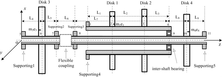
A finite element model of the aero-engine dual-rotor system is presented in Fig. 1, which is composed of a high-pressure rotor (rotor 1, node 1 to node 4) with a higher rotation speed and a low-pressure rotor (rotor 2, node 5 to node 11) with a lower rotation speed . Rotor 2 is composed of low-pressure compressor rotor (node 5 to node 7) and low-pressure turbine rotor (node 8 to node 11), with are coupled by a flexible coupling. There are a total of 5 supports in the model, which are respectively located at node 5, node 7, node 8, node 1, node 11, having the linear stiffness. In addition, the inter-shaft bearing is located at node 4 (node 9), having the nonlinear stiffness denoted by the restoring forces. The disks 1-4, located respectively at node 2, node 3, node 6 and node 10, represent the concentrations of high-pressure compressor disks, high-pressure turbine disks, low-pressure compressor disks and low-pressure turbine disks.
Fig. 1Finite element model of a dual-rotor system coupling by the cylindrical roller inter-shaft bearing
2.2. Model of flexible coupling misalignment faults
Misalignment in gear coupling includes parallel, angular and the combined conditions as shown in Fig. 2(b)-(d)) [19]. The coupling consists of two half parts, each with the driving shaft and driven shaft connection. The two half-couplings rotate around their own center lines and engage with the shell separately. The shell is forced to revolve around both center lines of half-couplings during a whirl process and its center may move along a planar circle.
According to the study of Han [8], central axis of the shell goes along a cylindrical surface as the coupling runs with parallel misalignment. When angular misalignment appears in the coupling, central axis of the shell spins and swings continuously between two half-couplings and its motion trace is a double-cone surface. If the coupling works with both angular and parallel misalignment, the central-axis trace of the shell is a hemi double-cone surface which is between cylindrical and double-cone surfaces. Different motion styles of the shell in various misalignment conditions are shown in Fig. 2(f)-(h).
Fig. 2Misalignment conditions and the relevant central-axis traces of the shell
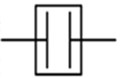
a) Alingment
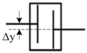
b) Parallel misalignment
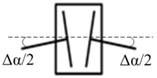
c) Angular misalignment
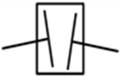
d) Combined misalignment

e) Straight line
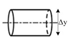
f) Cylindrical surface
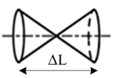
g) Double-cone surface
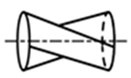
h) Hemi double-cone surface
For parallel misalignment fault, the inertial centrifugal force acting on right and left side of the rotor system can be expressed as:
where and are the inertial centrifugal force acting on left side of the rotor system in two directions, and are the inertial centrifugal force acting on right side of the rotor system in two directions, is the mass of the shell, is the amount of misalignment for parallel misalignment, is the rotating speed of rotor, is the initial angle.
For angular misalignment fault, the inertial centrifugal force acting on left side (, ) of the rotor system can be expressed as:
And the inertial centrifugal force acting on right side (, ) of the rotor system can be expressed as:
where is the mass of the shell, is the amount of misalignment for angular misalignment, is the assemble distance between two half-couplings, is the rotating speed of rotor, is the initial angle.
For combined misalignment fault, the inertial centrifugal force acting on the rotor system can be obtained by the accumulation of the Eq. (1) and (2).
2.3. The inter-shaft bearing model and the supports model
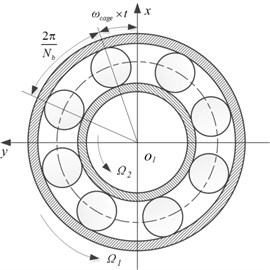
The inter-shaft bearing is a kind of bearing which located between the high-pressure rotor and the low-pressure rotor. Most of the inter-shaft bearings are the cylindrical roller bearings for the aero-engine dual-rotor system. Its main function is to transmit the force of low-pressure rotor to high-pressure rotor. Generally, the inner race of the inter-shaft bearing is built on the shaft of the low-pressure rotor, and the outer race is built on the shaft of the high-pressure rotor. In this paper, we consider that the two rotors rotate in the same direction. Fig. 3 shows the real object and the schematic diagram of the cylindrical roller inter-shaft bearing, in which, the considered bearing has equispaced elements rolling on the surface of the inner and outer races.
Fig. 3The schematic diagram of the inter-shaft bearing
For the inter-shaft bearing, the total restoring force is the sum of restoring force from each of rolling elements and its components in the and directions are [24]:
where is the Hertz contact stiffness related to the shape and the material of contact objects, is a Heaviside function , is the number of the rolling elements. is the normal contact deformation between the th element and the races, is given by the location of the th element, is assumed as , , and is the angular velocity of the cage, can be expressed as , where and are, respectively, the rotating angular velocity and the radius of the inner race, and represent, respectively, the rotating angular velocity and the radius of the outer race.
For the supports 1-4 and support 6, the following relationship can be obtained through the assumption of the linear restoring force:
where and are the elastic forces, and are the elastic deformations, and are the supporting stiffness in direction and direction.
2.4. Motion equations of the dual-rotor coupling system with misalignment faults
Based on the finite element method of rotor dynamic [25, 26], the rotor system model can be divided into rigid disks, elastic shaft segments and linear bearing supports as shown in Fig. 1. For the th elastic shaft element, the nodal displacements in an inertial coordinate system are expressed as:
where , represent node ’s displacements and , represent node ’s displacements. And we have:
The equations for the rigid disks are:
where:
The equations for the elastic shaft element are:
In which, , and are given as follows:
The equations for the linear bearings are:
where , .
According to Eqs. (6) to (9), and with the consideration of the factor of the inter-shaft bearing, the motion equations of the assembled dual-rotor system coupling by the cylindrical roller inter-shaft bearing can be denoted as:
where , are the assembled mass matrixes, , are the damping matrixes (the proportional damping method is used in this paper, so we have ). , are the stiffness matrixes. , are the vectors of the unbalance excitation of the rotor 1 and rotor 2, , are the gravities vectors. , are the vectors of the inertial centrifugal excitation of the rotor 1 and rotor 2, can be expressed as:
And , are the restoring forces vectors caused by the inter-shaft bearing, given as:
Then from Eq. (10), the motion equations of the dual-rotor system coupling by the cylindrical roller inter-shaft bearing can be expressed as:
Letting:
then Eq. (13) can be transformed into:
And the unbalance excitation vectors can be expressed as:
In which, , are the rotation speeds of rotor 1 and rotor 2. , are the unbalance excitation vectors of rotor 1, where disk 1 has an unbalance mass with an eccentricity . , are the unbalance excitation vectors of rotor 2, where disk 3 and disk 4 have an unbalance mass with a eccentricity and respectively. By letting , represents the speed ratio, and substituting Eq. (15) into Eq. (14), we obtain the motion equations of the dual-rotor system coupling by the cylindrical roller inter-shaft bearing:
In which, , and are 22×22 matrixes, , , , , , , and are 22×1 vectors.
3. Solutions and nonlinear response analysis
The numerical calculations for Eq. (16) are taken to demonstrate the nonlinear responses of the dual-rotor-bearing system with flexible coupling misalignment faults. Based on Eq. (16), the nonlinear response characteristics of the system are analyzed via the Fourth-order Runge-Kutta method in this section.
Amplitude value defined by the effective value, which gives a clearer observation of the nonlinear responses with dual unbalanced excitations, denoted by [27]:
where is the displacement for the time , is the average displacement of the steady-state response for sufficient times .
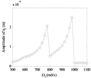
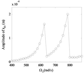
Fig. 4 shows the relationship between the rotation speed and the amplitude value of the rotor 1 and rotor 2 for an alignment dual-rotor bearing system 50 μm, 1.7×10⁻⁵ m, 5.0×10⁻⁵ m, 0.8). Form Fig. 4, the basic dynamic characteristics of the dual-rotor bearing system can be seen. Furthermore, the jumping phenomenon and the hard resonant hysteresis characteristics are shown.
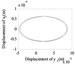
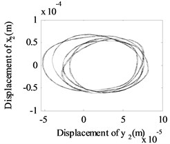
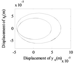
In order to give a deep and detailed insight into the properties shown in Fig. 4, the whirling orbits and the amplitude power spectrums at the rotation speed of 600 rad/s, 480 rad/s are used to analyze the nonlinear responses of the system, as shown in Fig. 5. The whirling orbit is a circular in node 6 in Fig. 5(b), and the frequency components are only in Fig. 5(e), which shows the basic dynamic characteristics of a linear single rotor system. And the whirling orbits are all superimposed circular for node 2 and node 10 in Fig 5(a) and 5(c), the super-harmonic frequency components (2 in Fig. 5(d), 2 and 3 in Fig. 5(f)) and the combined frequency components (-, 2- in Fig. 5(d), -, , 2-, 3- in Fig. 5(f)) appear except the basic frequency components of and , which shows the basic dynamic characteristics of a nonlinear dual-rotor bearing system.
Fig. 4Vibration amplitudes versus rotation speeds for an alignment dual-rotor bearing system with no fault (γ0= 50 μm, e1= 1.7×10⁻⁵ m, e2=e3= 5.0×10⁻⁵ m, β= 0.8): a) for x2 in rotor 1, b) for node x10 in rotor 2
a)
b)
3.1. Effect of amount of the parallel misalignment () on unbalanced vibration signal
In order to give a deep and detailed insight into the properties the unbalanced vibration, the Fast Fourier Transform (FFT) is used to analyze the nonlinear response signal.
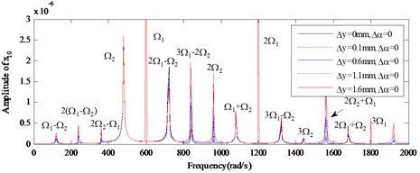
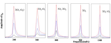
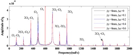
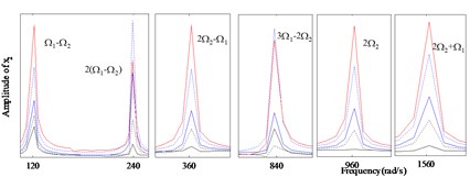
Vibration amplitudes power spectrum versus different amount of the parallel misalignment () ( 0: 0, 0.1 mm, 0.6 mm, 1.1 mm, 1.6 mm) at rotation speed of 600 rad/s, 480 rad/s are analyzed detailedly for the nonlinear responses of the dual-rotor-bearing system with parallel misalignment faults, as shown from Fig. 6 to Fig. 8. In Fig. 6, and Fig. 8, the super-harmonic frequency components and the combined frequency components can be seen except the basic frequency components of and , and with the increase of (from 0 mm to 1.6 mm), the frequency components 2 appear, besides, the amplitudes of the responses at the frequency components 2(-), 2-, 3-2, 2, 2 get larger for node 2 in Fig. 6(b) and node 10 in Fig. 10(b). The frequency components are only in at node 6 in Fig. 7 for 0, 0, but with the increase of (from 0.1 mm to 1.6 mm), the frequency components 2 appears and the amplitudes of the responses get larger. It is also indicated the vibration characteristics of misalignment faults in rotor 2 can be transmitted to the rotor 1, which has already been shown in [23], but the increase of the amplitudes at the combined frequency components related to is a new phenomenon found in this study.
Fig. 5The whirling orbits and the amplitude power spectrum for Ω1= 600 rad/s, Ω2= 480 rad/s: a)-c) the whirling orbits, d)-f) the amplitude power spectrum
a) Node 2
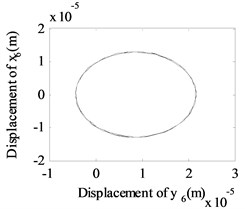
b) Node 6
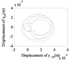
c) Node 10
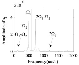
d) Node 2
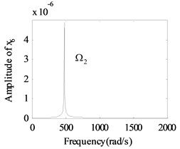
e) Node 6
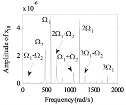
f) Node 10
Fig. 6The amplitude power spectrum for different amount of the parallel misalignment (Δy) of x2
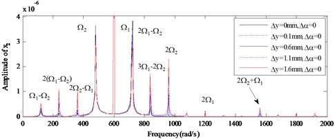
a) Global view
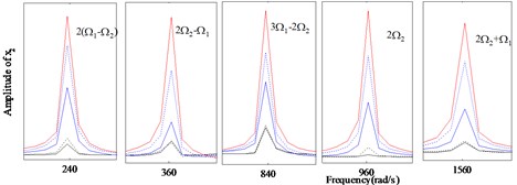
b) Enlarged view
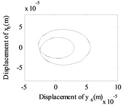
In addition, the whirling orbits for low-pressure compressor rotor (node 6) are inner-looped (two loops) at rotation speed of 600 rad/s, 480 rad/s in Fig. 9, and this phenomenon is confirmed in Ref. [16] (Fig. 11), Ref. [19] (Fig. 11) and Ref. [28] (Fig. 3). And accompanied by an increase in from 0.6 mm to 1.6 mm, the whirling orbits increased significantly, it means the misalignment signal is increased.
Fig. 7The amplitude power spectrum for different amount of the parallel misalignment (Δy) of x6
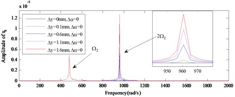
Fig. 8The amplitude power spectrum for different amount of the parallel misalignment (Δy) of x10
a) Global view
b) Enlarged view
Fig. 9The whirling orbits for Δα= 0, Ω1= 600 rad/s, Ω2= 480 rad/s: a) Δy= 0.6 mm, b) Δy= 1.1 mm, c) Δy= 1.6 mm
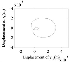
a)
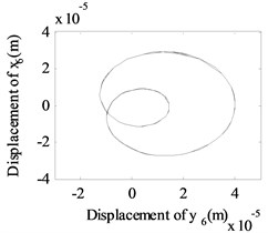
b)
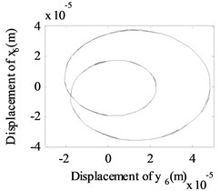
c)
3.2. Effect of amount of the angular misalignment () on unbalanced vibration signal
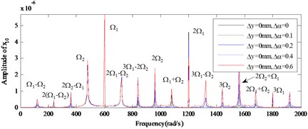
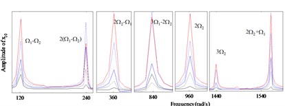
Vibration amplitudes power spectrum versus different amount of the angular misalignment () ( 0: 0, 0.1, 0.2, 0.4, 0.6) at rotation speed of 600 rad/s, 480 rad/s are analyzed for the nonlinear responses of the dual-rotor-bearing system with angular misalignment faults, as shown from Fig.10 to Fig. 12. In Fig. 10, and Fig. 12, the super-harmonic frequency components and the combined frequency components can be seen except the basic frequency components of and , and with the increase of (from 0 mm to 0.6 mm), the frequency components 2 appear, besides, the amplitudes of the responses at the frequency components -, 2-, 2, 2 get larger for node 2 in Fig. 10(b) and node 10 in Fig. 12(b). The frequency components are only in at node 6 in Fig. 11 for 0, 0, but with the increase of (from 0 mm to 0.6 mm), the frequency components 2 appears and the amplitudes of the responses get larger.
Fig. 10The amplitude power spectrum for different amount of the angular misalignment (Δα) of x2
a) Global view
b) Enlarged view
Fig. 11The amplitude power spectrum for different amount of the angular misalignment (Δα) of x6
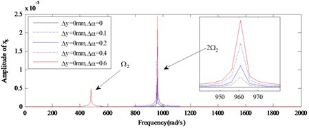
Fig. 12The amplitude power spectrum for different amount of the angular misalignment (Δα) of x10
a) Global view
b) Enlarged view
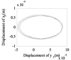
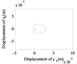
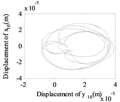
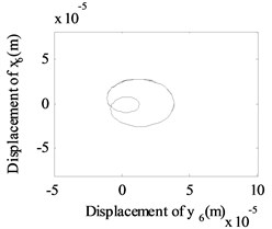
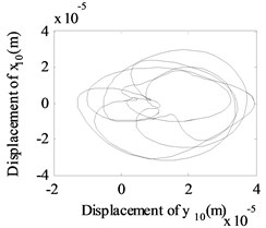
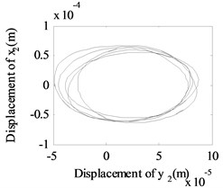
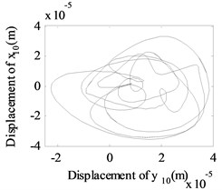
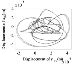
Fig. 13The whirling orbits for Δy= 0, Ω1= 600 rad/s, Ω2= 480 rad/s: a) Δα= 0.1, node 2, b) Δα= 0.1, node 6, c) Δα= 0.1 node 10, d) Δα= 0.2, node 2, e) Δα= 0.2, node 6, f) Δα= 0.2 node 10, g) Δα= 0.4, node 2, h) Δα= 0.4, node 6, i) Δα= 0.4 node 10, j) Δα= 0.6, node 2, k) Δα= 0.6, node 6, l) Δα= 0.6 node 10
a)
b)
c)

d)
e)
f)
g)
h)
i)
j)
k)
l)
Besides, the whirling orbits of node 2, node 6 and node 10 are given in Fig. 13 at rotation speed of 600 rad/s, 480 rad/s ( 0: 0.1, 0.2, 0.4, 0.6). Accompanied by an increase in , the whirling orbits (inner-looped) increased significantly for low-pressure compressor rotor (node 6), and the same phenomenon can be seen in Ref. [16], Ref. [19] and Ref. [28]. Besides, in this study, we find with an increase in , the whirling orbits for node 2 and node 10 are all become more complex.
From Fig. 5 to Fig. 13, we can conclude that, the multiplier excitation (2) are induced by the misaligned faults, and which will lead the complex nonlinear phenomenon for the dual-rotor system coupled by inter-shaft bearing. The nonlinear phenomenon caused by inter-shaft bearing can be seen more clearly at node 10 (high-pressure turbine rotor in rotor 1) which has a near distance with the inter-shaft bearing. And the complex nonlinear phenomenon caused by misaligned faults can be seen more clearly at node 6(the low-pressure compressor rotor system in rotor 2) which has a near distance with the flexible coupling misalignment faults between node 7 and node 8. And with the increase of the amount of parallel misalignment (angular misalignment) (), not only the super-harmonic frequency component 2 representing the misalignment signal increases for both rotor 2 and rotor 1, but also the responses at the combined frequency components , etc. also get larger, which indicates that the vibration characteristics of misalignment faults in rotor 2 can be transmitted to the rotor 1.
4. Conclusions
In the present work, the nonlinear response characteristics of aero-engine dual-rotor-bearing system with flexible coupling misalignment faults have been studied. The dual-rotor system which consists of a high-pressure rotor (rotor 1) and a low-pressure rotor (rotor 2) has been modeled by finite element method considering the excitations induced by the misalignment faults in rotor 2, the unbalance excitations of the two rotors, and the gravities. And the inter-shaft cylindrical roller bearing has been modeled as a kind of restoring force with 10/9 fractional exponential, where the radical bearing clearings and the Hertz contact forces were considered. The numerical calculation has been employed to obtain the nonlinear responses of the system, the hardening type hysteresis characteristics as well as jump phenomenon for the nonlinear responses of the dual-rotor-bearing system. Accordingly, the nonlinear responses affected by the amount of the parallel misalignment and angular misalignment have been discussed in detail. It has been shown that, with the increase of (), not only the super-harmonic frequency component 2 representing the misalignment signal increases for both rotor 2 and rotor 1, but also the responses at the combined frequency components 2, 2 etc. also get larger, which indicates that the vibration characteristics of misalignment faults in rotor 2 can be transmitted to the rotor 1. The results obtained in this paper will be helpful for recognizing the nonlinear dynamic characteristics of aero-engine dual-rotor-bearing systems with misalignment faults.
References
-
Lee Y. S., Lee C. W. Modelling and vibration analysis of misaligned rotor-ball bearing systems. Journal of Sound and Vibration, Vol. 224, Issue 1, 1999, p. 17-32.
-
Xu M., Marangoni R. D. Vibration analysis of a motor-flexible coupling-rotor system subject to misalignment and unbalance, Part I: theoretical model and analysis. Journal of Sound and Vibration, Vol. 176, Issue 5, 1994, p. 663-679.
-
Dewell D. L., Mitchell L. D. Detection of a misaligned disk coupling using spectrum analysis. Journal of Vibration and Acoustics, Vol. 106, Issue 1, 1984, p. 9-16.
-
Saavedra P. N., Ramírez D. E. Vibration analysis of rotors for the identification of shaft misalignment, part 1: theoretical analysis. Proceedings of the Institution of Mechanical Engineers Part C: Journal of Mechanical Engineering Science, Vol. 218, Issue 9, 2004, p. 987-999.
-
Tsai C. Y., Huang S. C. Transfer matrix for rotor coupler with parallel misalignment. Journal of Mechanical Science and Technology, Vol. 23, Issue 5, 2009, p. 1383-1395.
-
Lees A. W. Misalignment in rigidly coupled rotors. Journal of Sound and Vibration, Vol. 305, Issues 1-2, 2007, p. 261-271.
-
Jalan A. K., Mohanty A. R. Model based fault diagnosis of a rotor-bearing system for misalignment and unbalance under steady-state condition. Journal of Sound and Vibration, Vol. 327, Issues 3-5, 2009, p. 604-622.
-
Han J. Study on fault properties of the rotor connected by the gear coupling. Journal of Vibration Engineering, Vol. 3, 1996, p. 297-301.
-
Han Q. K., Wang M. L., Zhao G., Feng G. Q. A review of rotor systems with misalignment. Journal of Dynamic and Control, Vol. 14, Issue 1, 2016, p. 1-13.
-
Han Q., Chen Y., Zhang H., et al. Vibrations of rigid rotor systems with misalignment on squirrel cage supports. Journal of Vibroengineering, Vol. 18, Issue 7, 2016, p. 4329-4339.
-
Ma H., Wang X., Niu H., et al. Oil-film instability simulation in an overhung rotor system with flexible coupling misalignment. Archive of Applied Mechanics, Vol. 85, Issue 7, 2015, p. 893-907.
-
Mogal S. P., Lalwani D. I. Experimental investigation of unbalance and misalignment in rotor bearing system using order analysis. Journal of Measurements in Engineering, Vol. 3, Issue 4, 2015, p. 114-122.
-
Patel T. H., Darpe A. K. Experimental investigations on vibration response of misaligned rotors. Mechanical Systems and Signal Processing, Vol. 23, Issue 7, 2009, p. 2236-2252.
-
Sinha J. K., Lees A. W., Friswell M. I. Estimating unbalance and misalignment of a flexible rotating machine from a single run-down. Journal of Sound and Vibration, Vol. 272, Issues 3-5, 2004, p. 967-989.
-
Xu M., Marangoni R. D. Vibration analysis of a motor-flexible coupling-rotor system subject to misalignment and unbalance, part ii: experimental validation. Journal of Sound and Vibration, Vol. 176, Issue 5, 1994, p. 663-679.
-
Patel T. H., Darpe A. K. Vibration response of misaligned rotors. Journal of Sound and Vibration, Vol. 325, Issue 3, 2009, p. 609-628.
-
Li J., Hong J., Ma Y., et al. Modelling of misaligned rotor systems in aero-engines. Proceedings of the ASME 2012 International Mechanical Engineering Congress and Exposition, 2012.
-
Ma L., Zhang J. H., Lin J. W., et al. Dynamic characteristics analysis of a misaligned rotor-bearing system with squeeze film dampers. Journal of Zhejiang University – SCIENCE A, Vol. 17, Issue 8, 2016, p. 614-631.
-
Li H. L., Chen Y. S., Hou L., et al. Periodic response analysis of a misaligned rotor system by harmonic balance method with alternating frequency/time domain technique. Science China Technological Sciences, Vol. 59, Issue 44, 2016, p. 1717-1729.
-
Patel T. H., Zuo M. J., Darpe A. K. Vibration response of coupled rotor systems with crack and misalignment. ARCHIVE Proceedings of the Institution of Mechanical Engineers. Part C: Journal of Mechanical Engineering Science, Vol. 225, Issue 3, 2011, p. 700-713.
-
Huang Z., Zhou J., Yang M., et al. Vibration characteristics of a hydraulic generator unit rotor system with parallel misalignment and rub-impact. Archive of Applied Mechanics, Vol. 81, Issue 7, 2011, p. 829-838.
-
Zhang J. H., Ma L., Lin J. W., et al. Dynamic analysis of flexible rotor-ball bearings system with unbalance-misalignment-rubbing coupling faults. Applied Mechanics and Materials, Vol. 105, Issue 107, 2011, p. 448-453.
-
Q. K., Liao, M. F., Jiang, Y. F. The vibration features analysis of twin spool rotor with misalignment fault. Mechanical Science and Technology for Aerospace Engineering, Vol. 33, Issue 12, 2014, p. 1916-1920.
-
Zhang Z., Chen Y. Harmonic balance method with alternating frequency/time domain technique for nonlinear dynamical system with fractional exponential. Applied Mathematics and Mechanics, Vol. 35, Issue 4, 2014, p. 423-436.
-
Chiang H. W. D., Hsu C. N., Tu S. H. Rotor-bearing analysis for turbomachinery single and dual-rotor systems. Journal of Propulsion and Power, Vol. 20, Issue 6, 2004, p. 1096-1104.
-
Lu Z., Hou L., Chen Y., et al. Nonlinear response analysis for a dual-rotor system with a breathing transverse crack in the hollow shaft. Nonlinear Dynamics, Vol. 83, Issues 1-2, 2016, p. 169-185.
-
Hou L., Chen Y., Cao Q. Nonlinear vibration phenomenon of an aircraft rub-impact rotor system due to hovering flight. Communications in Nonlinear Science and Numerical Simulation, Vol. 19, Issue 1, 2014, p. 286-297.
-
Li Z. G., Li M. Non-linear dynamics of a flexible multi-rotor bearing system with a fault of parallel misalignment. Applied Mechanics and Materials, Vols. 138-139, 2012, p. 104-110.
Cited by
About this article

The authors would like to acknowledge the financial supports from the National Key Basic Research Program (973 Program) of China (Grant No. 2015CB057400), the National Natural Science Foundation of China (Grant No. 11602070), China Postdoctoral Science Foundation (Grant No. 2017M622259) and National Natural Science Foundation of Shandong Province (Grant ZR2016AP06).
Zhenyong Lu derived the theoretical formulations, conducted the numerical simulations and wrote the manuscript. Xiaodong Wang contributed to the interpretation of results and writing of the manuscript. Lei Hou proposed the original idea and revised the manuscript. Yushu Chen supervised the research and revised the manuscript. Hongliang Li established the dynamic model for the misalignment fault rotor system, and contributed to the numerical simulation.
