Abstract
The article analyzes the motion of a wheelset along a path of unequal length with shaft wear of the rails. The authors have studied the influence of an external disturbing force on the parametric system “wheel-rail”. The considered problem is solved on the basis of a mathematical model of interaction of a pair of wheels and an unequal rail, taking into account the additive effect of unequal stiffness on a rail vehicle. It is shown that taking into account the unequal elasticity of the track in the longitudinal direction allows to determine more precisely the resonance regions and to evaluate the decrease or increase of the acceleration level and the amplitudes of the impact of the unsprung mass of the rail vehicle.
Highlights
- Unsprung mass of the rail vehicle
- Additive effect of unequal stiffness on a rail vehicle
- Large number of differential equations
- Studied elements of the dynamic system
- Railway platform-turnstile-long-length cargo
- Devices in the connection of wagons
1. Introduction
An analysis of studies of transient modes of train movement showed [1] that the coupling of freight cars with long loads, inter-car connections and bogies is a dynamic system with many degrees of freedom. When testing for impact, the coupler performs complex spatial vibrations due to the work of draft gears and spring suspension of the car, as well as the turnstile support and fastening device [2]. An analytical study of these oscillations in the most complete and general form leads to the need to compose and solve a system with a large number of differential equations [3]. The interdependence between numerous design parameters is complex, so it is almost impossible to accurately assess the effect of one or another parameter on the dynamic qualities of cars. Therefore, a complex spatial system is usually replaced by a simpler (idealized) calculation scheme with a limited number of degrees of freedom, which retains the main properties of the considered dynamic system, as applied to specific problems. For this, a number of assumptions are usually introduced that simplify the calculation schemes [4]. When justifying the choice of simplifications of the calculation scheme, the goal of the forthcoming study plays an important role. The assumptions are chosen in such a way that when establishing the basic laws of motion of the studied elements of the dynamic system, the calculation error would not exceed the error of the experimental data [5-6]. In this case, the distorted idea of the movement of other elements of the system does not matter [7]. Studying the regularities of fluctuations of long-length cargo and establishing the optimal parameters of shock-absorbing devices on the basis of the mathematical model of the dynamic system “railway platform-turnstile-long-length cargo”, taking into account the dynamics of collision of cars, is an extremely difficult task.
2. Materials and methods
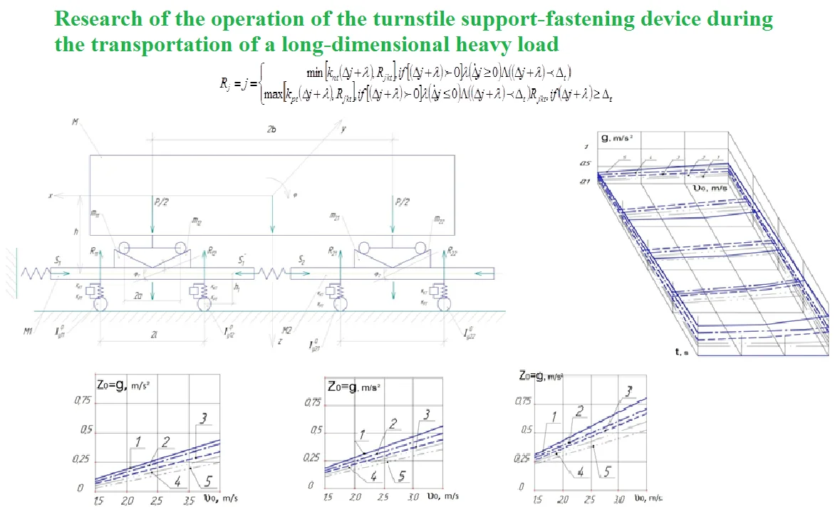
Taking into account the accepted assumptions [8-9], the design scheme for studying the parameters of inter-car connections and the system for depreciation of long-length cargo during collisions is shown in Fig. 1. The following designations are adopted on the diagram:
is the longitudinal force acting from the stops; , is the longitudinal forces of inter-car connection, due to the characteristics of draft gear type Sh2V, – in loading mode; where is the force of the initial tightening of the devices under loading immersion, respectively and devices in the connection of wagons; is the total stroke of two draft gears (); , , , – forces acting from the spring complexes of bogies, , 1, 2, 3, 4. Where – is the full force compressing the spring set: 0, if = 0:
Fig. 1Settlement scheme wagon coupler turnstile long load
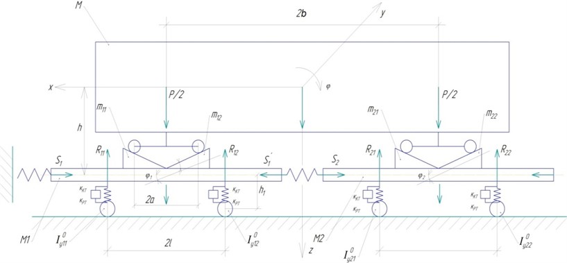
is the reaction kits in the case when the springs do not work; is the rigidity of spring sets during unloading (); (); is the energy dissipation factor of spring sets; is the stiffness of spring sets when they are loaded; is the static deflection of spring sets, ; , , , is the full deflection of spring sets, at which they close; is the stiffness (viscosity) press, simulating deformation wheelsets, sidewalls, bolsters and track (taken into account at stages when spring sets are not working); is the integration step in the numerical solution of the problem; , , is the weight of platforms and long cargo; , is the masses of fixed parts of the turnstile; , is the masses of moving parts of the turnstile; , – is the moment of inertia of platform bodies about the y-axis; , , , is the moments of inertia of wheelsets; is the distance from the center of mass of the body to the plane passing through the axles of the wheel sets (it is assumed that the plane of support of the body on the spring sets coincides with this plane); is the distance from the center of gravity of the body to the longitudinal plane of the coupler axis; 2 is the wagon base; 2 is the distance between the support points of a long load:
The kinetic energy of the considered movement of the platform coupler with long loads on the turnstile will take the form:
Substituting Eq. (4) and Eq. (3), we obtain the general expression for the kinetic energy:
Possible work equations:
Substituting into Eq. (6) the equations of spring sets settlement:
Then the equation of possible work will take the form:
We find the partial derivatives of the kinetic energy with respect to the generalized velocities, and then their time derivatives are calculated to compose differential equations; the Lagrange equations of the second kind are used:
3. Results and discussion
The numerical values of the parameters and their dimensions are presented in Figure 1. The problem is solved by the Runge Kutta method by stepwise integration [8-9].
Fig. 2Graph of vertical accelerations of the load on the impact velocity and impact pulse duration, M= 3,5; 6,5; 9,0; 12; 15,0 T∙m-1∙s2, respectively 1, 2, 3, 4, 5 at Kpt= 400 T∙m-1
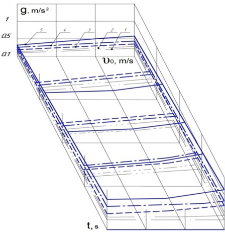
Fig. 3Graph of vertical accelerations of a long load versus impact speed, M= 3,5; 6,5; 9,0; 12,0; 15,0 T∙m-1∙s2, respectively 1, 2, 3, 4, 5 at s1= 13∙106 kN, Kpt= 400 T∙m-1
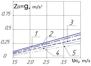
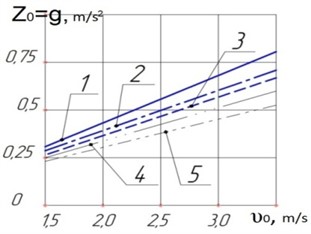
Fig. 4Graph of vertical displacements of a long load versus impact speed, M= 3,5; 6,5; 9,0; 12,0; 15,0 T∙m-1∙s2, respectively at s1= 2∙106 kN, Kрt=10∙106 m/kN
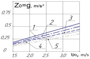
Fig. 5Graph of vertical accelerations of a long load from the speed of collisions, M=3,5; 6,5; 9,0; 12,0; 15,0 T∙m-1∙s2, respectively at s1= 3,5∙106 kN, Kрt= 13∙10 m/kN
4. Conclusions
Based on the above, it has been established that more effective protection of a long load cannot be carried out by additional suspension. Therefore, it is advisable to consider the possibility of reducing vertical accelerations by reducing the rigidity of the spring suspension of loaded bogies. The study of the influence on the vertical dynamics was carried out on the basis of the TsNII-KhZ bogie, where the stiffness of the spring set is 400 T.m-1.
Analysis of the results of investigations of vibrations in the vertical plane made it possible to draw the following conclusions:
1) An increase in the rigidity of the inter-car connection leads to an increase in the accelerations and movements of the turnstile device. At the same time, an increase in the dissipation factor from 0.25 to 0.9 leads to a decrease in the acceleration of the turnstile device and its displacement by 10-30 %.
2) Increasing the loading of the turnstile increases the degree of its depreciation, i.e. when the platform coupling is fully loaded and the duration of the shock pulse is 0.2-0.4 s, the acceleration of the lower support beam of the turnstile and platforms is equivalent.
3) Due to insignificant accelerations and displacements from the action of dynamic forces in the vertical plane and sufficient rigidity of the spring sets of the TsNII-KhZ bogie, additional suspension of a long load is not advisable.
References
-
Y. Adilkhanov et al., “Experimental researching of dynamic quality and safety movement of half-wagons which have trolleys with diagonal connections,” Journal of Engineering and Applied Sciences, Vol. 14, No. 16, pp. 5831–5839, Nov. 2019, https://doi.org/10.36478/jeasci.2019.5831.5839
-
J. Musayev, Y. Yelzhanov, M. Aliyarova, A. Yelemanova, and A. Zhauyt, “Shock-impulse diagnosis of railway,” in 17th International Scientific Conference Engineering for Rural Development, Vol. 17, pp. 1618–1623, May 2018, https://doi.org/10.22616/erdev2018.17.n551
-
N. Igembayev, J. Musayev, A. Zhauyt, G. Balbayev, A. Auezova, and G. Smailova, “The researching of the dynamic properties of long-wheelbase platforms for the transportation of large-capacity containers,” Journal of Measurements in Engineering, Vol. 5, No. 3, pp. 182–193, Sep. 2017, https://doi.org/10.21595/jme.2017.19094
-
J. Musayev, A. Zhauyt, T. Buzauova, G. Mamatova, Z. Yessenkluova, and G. Abdugaliyeva, “The experimental determination of the stress calculation and relative strains in the span elements of railway bridges under the influence of the rolling equipment,” Journal of Measurements in Engineering, Vol. 5, No. 3, pp. 125–133, Sep. 2017, https://doi.org/10.21595/jme.2017.19025
-
E. Adilkhanov, S. Sekerovа, J. Musayev, A. Zhauyt, S. Yussupova, and A. Alimbetov, “Simulation technique of constant contact side bearings of freight car bogies,” Journal of Measurements in Engineering, Vol. 5, No. 3, pp. 142–151, Sep. 2017, https://doi.org/10.21595/jme.2017.19050
-
V. Solonenko, N. Mahmetova, J. Musayev, M. Kvashnin, A. Alpeisov, and A. Zhauyt, “Some aspects of the experimental assessment of dynamic behavior of the railway track,” Journal of Theoretical and Applied Mechanics, Vol. 55, No. 2, p. 421, Apr. 2017, https://doi.org/10.15632/jtam-pl.55.2.421
-
V. Solonenko, N. Mahmetova, J. Musayev, M. Kuashnin, A. Zhauyt, and T. Buzauova, “Modeling of dynamic characteristics of freight car withoptimized parameters of wedge-type shock absorber,” Journal of Vibroengineering, Vol. 19, No. 2, pp. 1197–1213, Mar. 2017, https://doi.org/10.21595/jve.2017.16901
-
J. Musayev, A. Zhauyt, Y. Kassenov, N. Abdish, and O. Akhmet, “Characterization of tribological behavior of high performance rail steel,” Vibroengineering Procedia, Vol. 7, pp. 118–123, Aug. 2016.
-
J. Musayev et al., “The influence of operational factors on the contact-fatigue effect of couple of wheel-rail friction in curves of small radius,” Vibroengineering Procedia, Vol. 8, pp. 263–268, 2016.
About this article

The authors have not disclosed any funding.
The datasets generated during and/or analyzed during the current study are available from the corresponding author on reasonable request.
The authors declare that they have no conflict of interest.
